
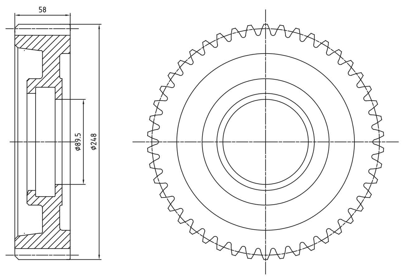
With the rapid development of automobile industry, precision forming of spur gear has become an inevitable trend in the development of forging industry. The forging forming of the tooth part can make the metal streamline of the tooth part complete and continuous, the strength of the tooth part is better than that of machining, save process materials and reduce production cost. For large modulus and large specification spur gears, due to the problems of poor filling of tooth corners, difficult die discharge and low die life, at present, the tooth blank is basically forged first, and then the tooth processing is completed by machining. In this paper, the precision forming process of a common large-size and large modulus spur gear part on a heavy truck is developed, and the precision forming of external spur gear is finally realized. Figure 1 is the product drawing of large module and large specification spur gear parts.
I. Forging drawing and equipment selection
Drawing of spur gear forging
As can be seen from the above part drawing, the maximum outer circle of this part is φ 248mm, tooth width of 58mm, modulus of 5.22mm and number of teeth of 46. It is a typical large specification and large modulus spur gear part. In order to ensure the yield, the tooth part is designed with a margin of 1mm on one side and 1.3mm on the other side. At the same time, considering the die out problem, the die out angle at the outer circle is 0.5 °, and the straight tooth cylindrical gear forging is shown in Fig. 2.
Selection of production equipment
The calculation formula of forming force is p = (50 ~ 70) f, where f is the projected area of spur gear forging (cm2) and P is the deformation force (KN). Due to the complexity of spur gear forging, the selection coefficient is 70 and the calculation P is about 3.44 × 1000000kN。 According to practical experience, the nominal force of the equipment should be about 1.2 times larger than the deformation force. The calculated nominal force of the equipment is 4128t. Finally, 6300t hot die forging press is selected for production.
II. Mold design and DEFORM-3D simulation
Design ideas
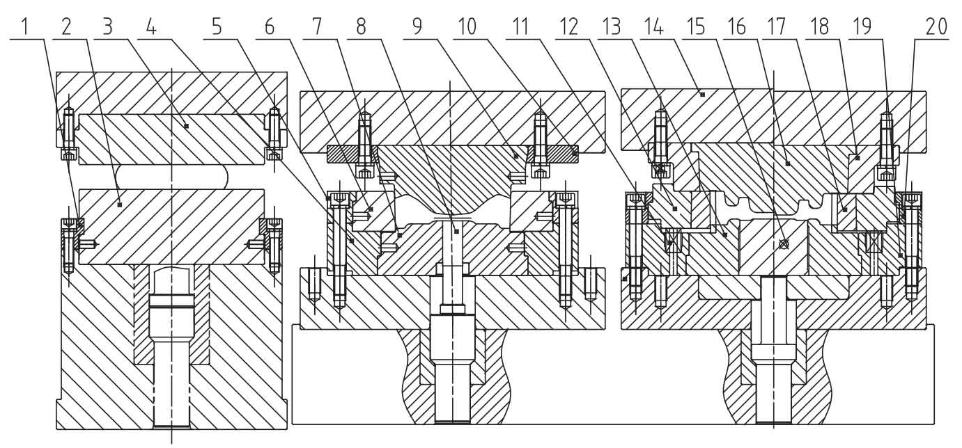
Because the forging blank of spur gear weighs about 14kg and has a large number of teeth, if the pre forging has teeth, the pre forging gear blank is difficult to be quickly and accurately placed in the final forging cavity, resulting in too fast cooling of the teeth and poor filling of the teeth during final forging. Therefore, the design of pre forging process is only a simple material distribution, and the tooth shape is not designed. The pre forging to the final forging is positioned by the tooth root circle. The final forging adopts the floating structure, and the center of the large ejector rod can be ejected, or the ring top can be adopted to ensure the smooth ejection of the forging blank during ejection. The specific die structure is shown in Figure 3.
DEFORM-3D forming simulation
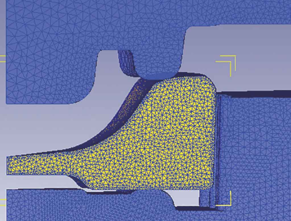
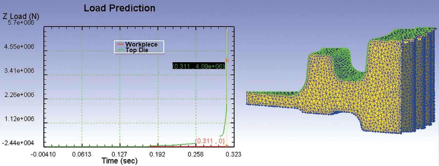
Due to the large tooth width of spur gear forging, more materials are used in the tooth part, and more materials are required at the outer contour during material separation, so the blank volume in the middle should be reduced as much as possible when designing the pre forging process. The pre forging to final forging is positioned through the root circle, as shown in Figure 4. Through several DEFORM-3D simulations, the forming scheme is finally determined. From the simulation results, it can be seen that when the strike force is 4896t, the teeth of spur gear forging are completely filled. See Fig. 5 for the specific forming effect.
III. Actual production situation and result analysis on site
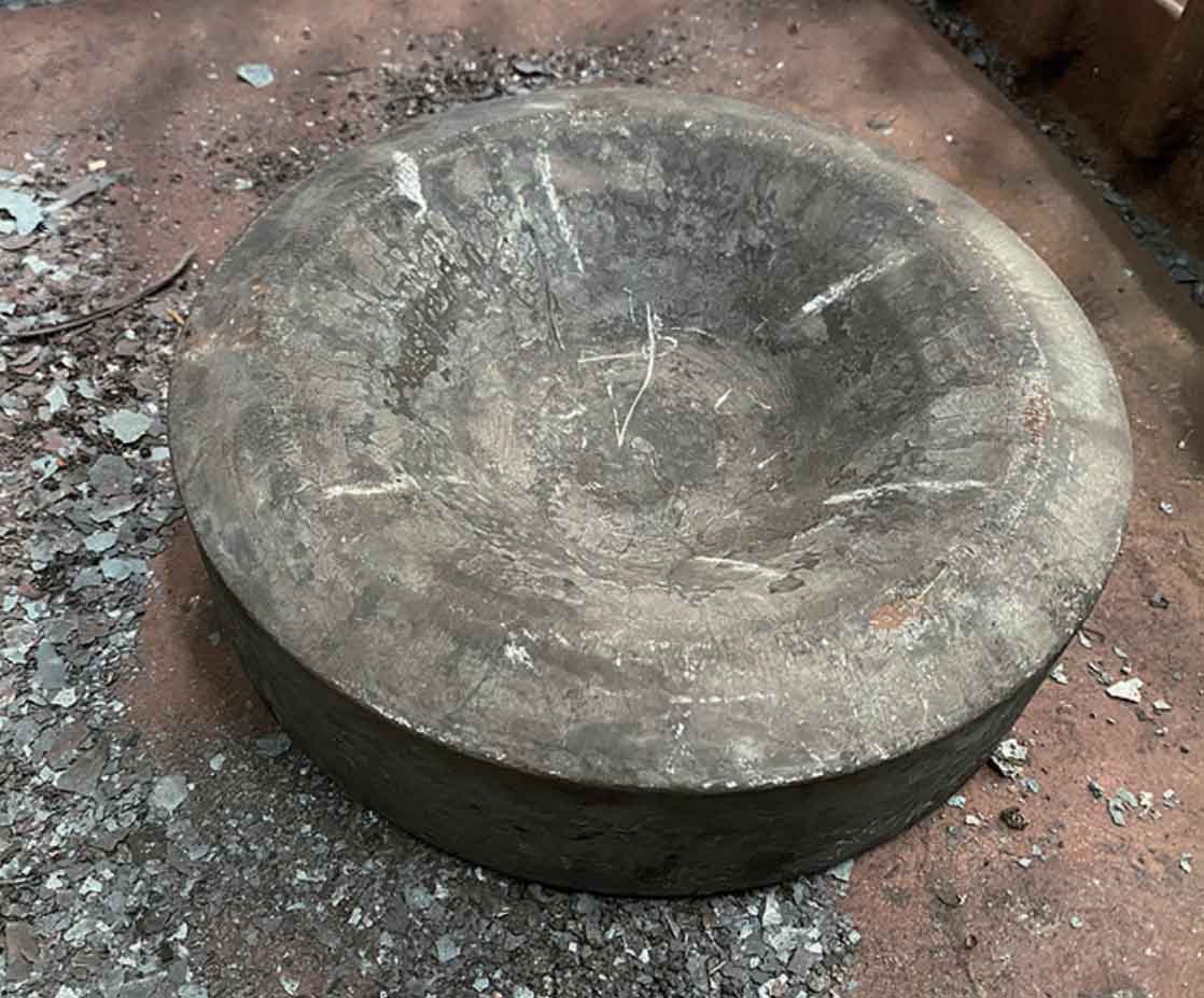
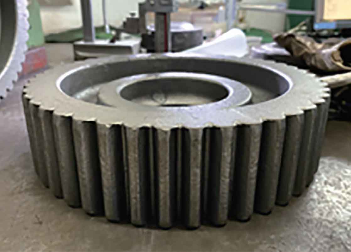
Graphite lubrication is selected for on-site production, and the forging temperature is 1200 ℃, which is produced on 6300t hot die forging press. Figure 6 shows the on-site pre forging blank, and Figure 7 shows the final forging blank. During the forging process, the pre forging to the final forging are positioned by the tooth root circle, and the positioning is stable. The center ejection is adopted, and the ejection is stable. The final production situation is basically the same as the simulation situation. The tooth part of spur gear forging is well filled, and the fullness of the lower part of the overall tooth width is better than that of the upper part. Because the tooth part has a 0.5 ° die out angle, the machining allowance of the upper part of the tooth width is greater than that of the lower part, which can effectively reduce the scrap rate.
IV. Conclusion
The precision forming process of large modulus and large gauge spur gear is developed. Through the analysis of die structure, blank allowance, equipment selection, DEFORM-3D simulation and production verification, the following conclusions are finally drawn:
(1) it is not recommended to design tooth profile for pre forging of large modulus and large gauge spur gear forgings. Pre forged belt teeth not only increase the die cost, but also reduce the temperature of the tooth too fast, which is not easy to be quickly put into the final forging cavity, resulting in poor filling of the tooth. Therefore, the pre forging process design can be simplified and positioned directly by the root circle.
(2) due to the large tooth width and large die sticking area of the tooth part, the annular ejector near the outer circle or the central large ejector rod shall be used to ensure the smooth die out of the spur gear forging during ejection.
(3) due to the complex tooth structure, when selecting straight cylindrical gear forging equipment, the deformation force shall be greater than at least 1.2 times, so as to ensure sufficient equipment capacity as far as possible and avoid equipment overload and equipment damage.
(4) during the production process, the material temperature should be controlled at about 1200 ℃ and should not be too low. Low material temperature will significantly affect the filling of teeth and lead to high scrap rate.
(5) if the stress of the tooth die is too large, the die material shall be reasonably selected to avoid the failure of the tooth die due to cracking during forging.