The processing of tooth surface point cloud in reverse engineering of spiral bevel gear is a very important process, which directly affects the quality of reconstructed 3D model. Due to the defects of scanning equipment, measurement methods, the quality of the surface of the scanned part and the environment, there are impurity point clouds generated by light and noise in the scanned point cloud. Therefore, before reconstructing the three-dimensional model of spiral bevel gear, it is necessary to process the scanned point cloud data accordingly. Point cloud data processing mainly includes point cloud alignment, point cloud segmentation, point cloud smoothing and data simplification.
1. Spiral bevel gear reverse engineering point cloud alignment
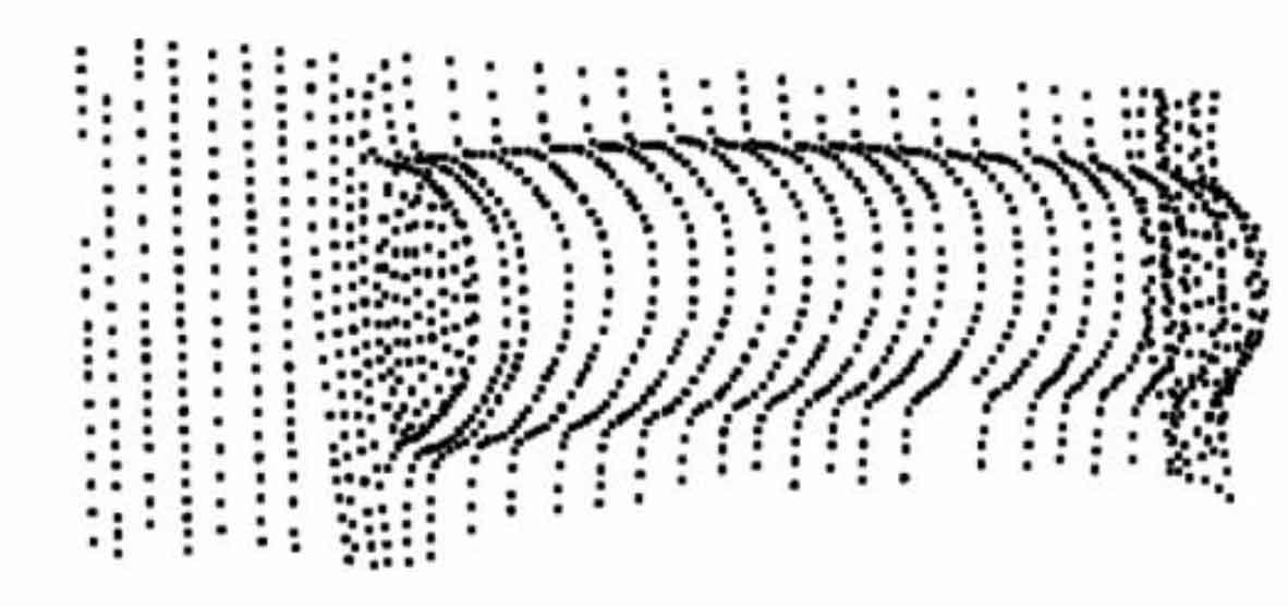
The point cloud obtained by scanning is simply processed by the grid doctor of Geomagic Studio software. After deleting nails and noise reduction, multiple point clouds are aligned. First, manually register the two point clouds to be aligned. Three points that are not collinear and face can not be found on the two point clouds to be aligned. Manually register the two point clouds so that the two point clouds can be roughly fitted together. At this time, the fitting point cloud obtained has a large error and cannot be used directly; Secondly, the two point clouds are registered globally. The global registration can make the two point clouds better aligned and reduce the alignment error of the two point clouds. The average deviation after global registration is 0.5% 120 114 mm; Finally, the fitting point cloud obtained is shown in Figure 1, with a total of 284280 points, and the minimum interval between two adjacent points is 0.5 2 mm。
2. Spiral bevel gear reverse engineering point cloud segmentation
Data segmentation is to divide the data belonging to the same sub surface type into areas with single features and no overlap, which provides convenience for surface model reconstruction. There are two methods for the segmentation of point cloud data: measurement segmentation and automatic segmentation:
(1) measurement based segmentation refers to the division of sub surfaces according to the physical model during the measurement process, so that different data can be displayed and processed in layers.
(2) automatic segmentation has two methods based on edge and face; The region with closed boundary is regarded as the final segmentation result based on edge. The method based on face is to divide the spatial points with similar geometric features into the same region.
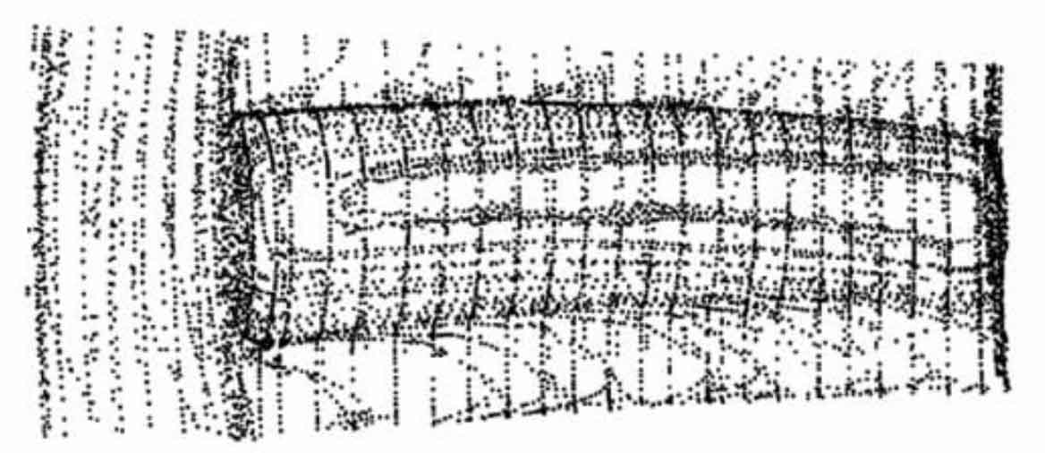
Imageware software provides two methods of automatic segmentation and manual segmentation in the reverse environment. Here, the automatic segmentation method based on the combination of edge and surface is used to segment the point cloud data of spiral bevel gear reverse engineering tooth surface. According to the different surfaces and their boundaries of the real object, the sub surfaces with different characteristics are divided, so that the characteristic data of the model are clear and It is clear, which is conducive to the hierarchical display and processing of data, and lays a good foundation for surface reconstruction. The point cloud data segmented by Imageware software is shown in Figure 2.
3. Point cloud smoothing of spiral bevel gear reverse engineering
Point cloud fairing mainly includes fairing point cloud, overall point cloud fairing, regional point cloud fairing and corner fairing. Standard Gaussian, average and median filtering algorithms are usually used. The weight of Gaussian filter in the specified domain is Gaussian distribution, and its average effect is small, which can better maintain the morphology of the original data. The average value of the sampling point of the average filter is the average value of the statistical value of each data point in the filtering window. The value of the sampling point of the median filter takes the median of the statistical value of each data point in the filtering window, which can well eliminate the data burr. In practical application, various filtering algorithms can be flexibly used according to the requirements of point cloud quality and modeling accuracy.

Before the smoothing of the point cloud, the clearance of the point cloud should be filled, and the clearance of the surface with low I accuracy and regular shape should be filled to improve the point cloud data and improve the re modeling accuracy. This paper mainly adopts the methods of smoothing point cloud and regional point cloud. As the spiral bevel gear has high requirements for the accuracy of the tooth surface, the Gaussian filtering algorithm is mainly used to smooth the tooth surface, which can effectively maintain the morphology of the tooth surface point cloud of spiral bevel gear reverse engineering, and the average and intermediate value filtering algorithm can be used for the non tooth surface point cloud, which can well eliminate the burr data and realize the smoothing of the point cloud, The smoothed spiral bevel gear point cloud is shown in Figure 3.
4. Point cloud data simplification of spiral bevel gear reverse engineering
After removing the impurities caused by noise and light and smoothing the point cloud, the points around the point cloud that are not conducive to modeling are removed. However, the point cloud also contains a large number of data points. Not all data points play a role in the re modeling. On the contrary, the processing speed of the software on the point cloud may be reduced due to too many data points. Therefore, under the condition of ensuring the accuracy of re modeling, we can simplify the data processing of point cloud data, reduce the number of point cloud data points, and improve the processing speed of Imageware software. There are two ways to simplify the point cloud data of spiral bevel gear reverse engineering: uniform sampling and distance sampling. Due to the different density of the collected data, distance sampling is adopted here to avoid more data loss and ensure the accuracy of the reconstructed model. The distance tolerance is 0 5 mm. The point cloud after data simplification is shown in Figure 4.