
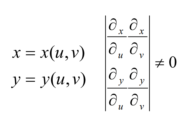
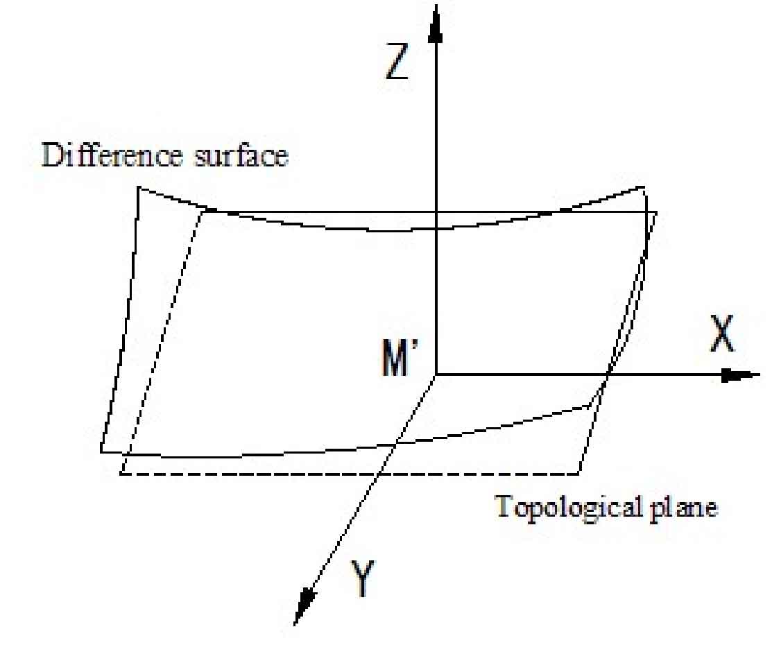
Difference surface is a widely used surface error analysis tool. It was initially applied to the error discrimination of first-order surface logarithmic spiral bevel gear. With the popularization of calculation application, it is gradually applied in spiral bevel gear. By using the discrimination tool of difference surface, the machining parameters of machine tool can be determined, the shape parameters of logarithmic spiral bevel gear tooth surface can be corrected, and the error analysis of logarithmic spiral bevel gear real tooth surface and theoretical tooth surface can be carried out. The formation principle of difference surface can be represented by a simple surface in two spaces. Let two space simple surface Σ The tooth surface of the gear is logarithmic bevel theory 1, Σ 2 is the detection tooth surface, where Σ 1 is R1 (U, V) ∈ CK (K ≥ 2). (U, V) ∈ e is the curve coordinate of Σ. The unit normal vector function of each point on Σ 1 is N1 (U, V). As shown in Figure 1, Σ t is a topological plane of Σ 1, the image of a point m on Σ t on Σ 1 is m ‘, with M’ as the origin, take two straight lines perpendicular to each other passing through point m ‘on Σ t plane as X and Y coordinate axes, and (U, V) and (x, y) have the following relationship:
If there is an objective function H (x, y), so that Σ 2 can be expressed as:
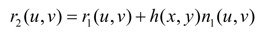
In a rectangular coordinate system with M ‘as the origin, relative to Σ 1 and Σ The vector surface formed by 2 is called difference surface, which is recorded as:
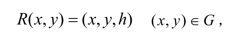
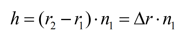
Solve h through the above formula:
According to the discrete data points on the difference surface actually obtained, the logarithmic spiral bevel gear of the machine tool adjustment parameters modifies the tooth surface space. The base of any surface available space is expressed as a vector {A0, A1, A2 ⋅ ⋅ ⋅}, and the difference surface equation can be expressed as a group of bases of the surface space:

Where h is the deviation value of the real tooth surface of logarithmic spiral bevel gear along the normal direction of the theoretical tooth surface; The 0-order coefficient reflects the position deviation of the two surfaces along the normal direction, the 1-order coefficient reflects the inclination degree between the two surfaces, and the 2-order coefficient reflects the curvature error between the two surfaces. Each order coefficient is used for the error evaluation of logarithmic spiral bevel gear, which corresponds to the 0-order error, 1-order error and 2-order error of logarithmic spiral bevel gear.
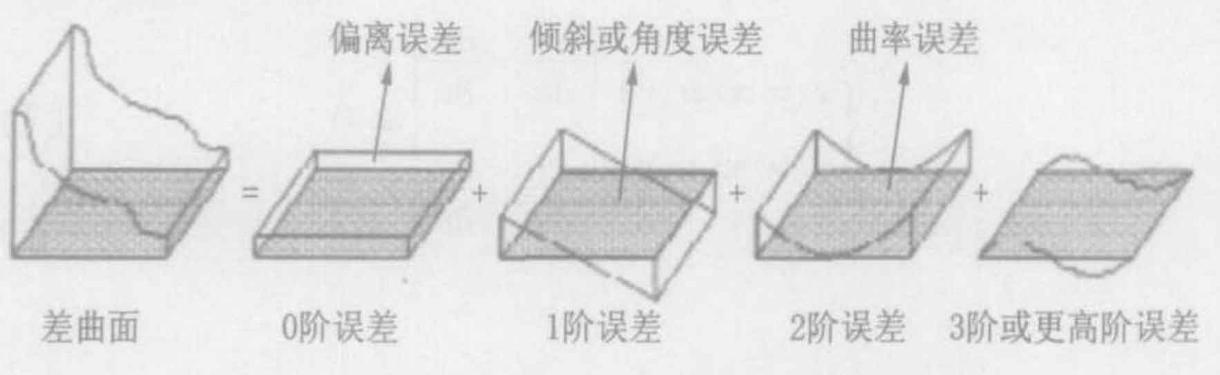
Fig. 2 shows the geometric meaning of the parameters of each order of the difference surface, which is also the guiding ideology for error analysis of the real tooth surface and theoretical tooth surface of logarithmic spiral bevel gear. This method of classifying the surface by order is easier to be processed by mathematical method. In the process of machining logarithmic spiral bevel gear, the machining error caused by the adjustment of tool path or machine tool parameters appears in the form of low-order error. The distance between the real tooth surface and the theoretical tooth surface of logarithmic spiral bevel gear is very small, so the deflection of the difference surface is also very small. Therefore, as long as the second-order or third-order model can fit the difference surface with high precision.