
In the process of gear hobbing, the machined materials and cutting conditions affect the unit cutting force of the hob, and the cutting thickness and width of the top edge and side edge of the hob are different in machining. Therefore, it can be considered that the unit cutting force is different at each position. They use turning instead of hobbing and adopt cross feed. The cutting edge of the turning tool is the same as each individual tooth of the hob, Simulate the cutting state of gear hobbing as much as possible. Considering two factors, that is, the change of material and cutting conditions, they found that the unit cutting force increases with the increase of the number of hobs, and the influence of cutting speed is very small. The main reason why the blank of different materials affects the unit cutting force is the chip adhered to the cutting edge, that is, the effect of chip buildup.
At the same time, Yoji meizaki studied the tooth profile error of gear in gear hobbing cutting, in order to explore the way to improve the machining accuracy of gear hobbing. This research mainly considers the influence of two factors, one is the geometric error of hob, the other is the installation error of hob. After calculation and actual measurement, it is found that the two results are in good agreement. Therefore, a new fixture is proposed to reduce the main factors of cutting force. The tooth profile error is analyzed from the perspective of tool geometric error and installation error, and the wear causes of tools are discussed from the cutting graphics, which are of certain significance to practical production and theoretical research.
Russia is a country based on heavy industry, which needs a large number of gears every year. Therefore, the research on gear hobbing processing is particularly urgent. In gear hobbing, the cutting force has a great impact on precision, machining quality, productivity and machine tool life. Knowing its numerical direction and change law is of great significance to the actual production of gear and the design of gear cutter and machine tool. Russian scholars have gradually established the mathematical model of gear hobbing process from the research on the cutting shape produced in the gear hobbing process. Russian scholars have proposed a method to determine the chip cross-section shape by computer. The central idea of this method is to determine the coordinates of the limit point of chip section. In gear hobbing, they regard the processed gear as stationary. The hobbing motion is completed by the hob. Each tooth of the hob cuts the processed gear in turn and finally envelops the gear tooth profile. Scholars from the former Soviet Union set a center tooth (serial number n = 0) to be stationary, and divided the cutter teeth participating in cutting into two areas along the axial direction of the hob: cutting in and cutting out. The selection of the center tooth is the cutter tooth whose tooth top center coincides with the common vertical line between the hob and whose relative angle is zero.
The main factor determining the unit cutting force is the change of chip thickness cut by hob in the machining process. Based on the analysis of the distribution of chip section boundary points and the possibility of cutting mode, 83 possible forms of chip from the left cutting edge, right cutting edge and top edge of hob teeth are determined. The chip width is determined by the length of the contact line between the cutting edge and the blank, and the chip thickness is determined by the ratio of the chip cross-sectional area to its width. For each cutting section shape, the formulas for calculating its width and thickness according to the boundary points are given. The change of cutting force is proportional to the change of cutting width b, while the chip thickness a has little effect on the cutting force. Therefore, the comprehensive coefficient K representing the number of cutting loads is obtained, which has the relationship formula B1 − λ a=K。 For the cutter rack and the whole hob, the relative position of the cutter cutting edge should be considered in the calculation of the cutting section parameters. The comprehensive coefficient characterizing the hob tooth load is Ka, and its relationship is:
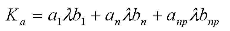
Where a1, an, ANP and B1, BN and BNP are the chip thickness and width corresponding to the left edge, top edge and right edge of the cutter tooth. According to the above method, Russian scholars compiled computer programs in FORTRAN language, and calculated the parameters of cutting section according to various typical cases of gear hobbing. The influence of cutting load on gear hobbing is comprehensively analyzed, and the reason for the maximum wear at the fillet of the tool is explained.