
The dual frequency induction quenching process of bevel gear includes electromagnetic induction heating process and quenching cooling process. The temperature field model of bevel gear obtained by induction heating has a great impact on the quenching quality. Observing the change of bevel gear temperature field with time is helpful to understand the characteristics of dual frequency induction heating of bevel gear. Dual frequency induction heating parameters: high frequency current frequency: 100kHz, high frequency current density: 6 × 10⁷a / m2, if current frequency: 6KHz, if current density: 2.0 × 10⁸a / m2, medium and high frequency output time ratio: 4:1, and the number of medium and high frequency switching is 60 in 30s.
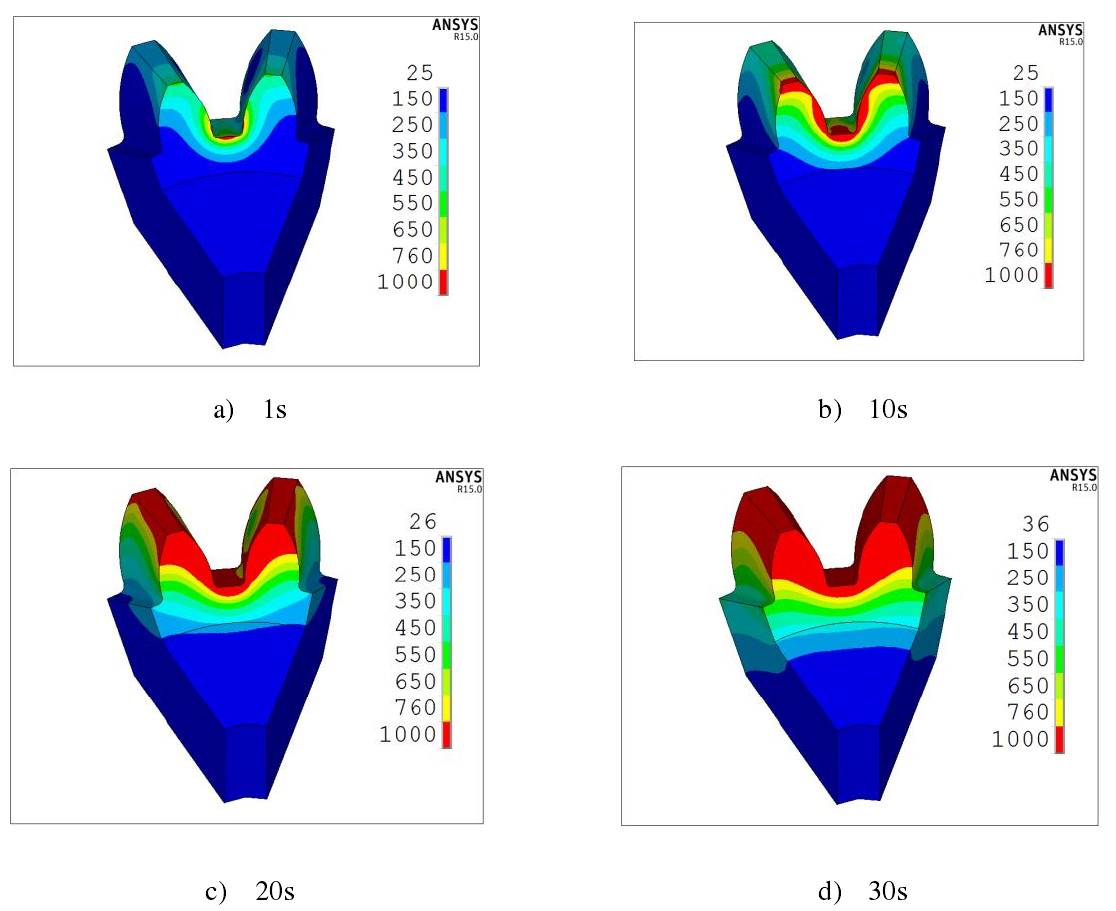
As shown in the figure, the temperature field at different times during the dual frequency induction heating process of bevel gear can be seen that the small end of bevel gear first reaches the austenitizing temperature of 760 º C, and then the tooth end, tooth top and tooth root reach the austenitizing temperature first than the tooth surface. Finally, at about 30s, the model of temperature field with uniform distribution along the tooth profile is obtained.
From the temperature field diagram at 1s and 10s, it can be seen that the temperature rise at the small end of the bevel gear is faster, which is caused by the structural characteristics of the bevel gear. Compared with the bevel gear tooth end, there is “sharp angle effect” at both ends of the bevel gear, resulting in high induction heating efficiency at the end of the bevel gear. Compared with the big end of the bevel gear, the small end has smaller structural size and higher induction heating efficiency, so the small end of the bevel gear first reaches the austenitizing temperature. At 20s, the crown and crown of the bevel gear reach the austenitizing temperature, which is because there is also a “sharp angle effect” at the crown of the bevel gear. The rapid temperature rise of the tooth root is due to the small distance between the induction coil and the tooth root, resulting in high induction heating efficiency at the tooth root. The bevel gear structure is relatively complex. The tooth size of the bevel gear is smaller than that of the tooth root, and the tooth root is connected with the matrix. In the process of induction heating, the temperature difference of the tooth root is large, the heat conduction effect is stronger, and there is “sharp angle effect” at the tooth top. Therefore, when designing the induction coil structure, The induction heating efficiency of the tooth root is improved by reducing the distance between the induction coil and the tooth root. After 30s, the tooth profile of the bevel gear obtained a more uniform temperature field.
In order to avoid over burning, the electrical parameters of induction heating need to be strictly controlled. As can be seen from the figure, although the temperature at both ends of the bevel gear is high, it is not “overburned”. Comparing figures b), c) and D), when the time increases by 10s, the maximum temperature of the bevel gear increases by about 35 º C, and the temperature distribution is significantly improved. The two ends of the bevel gear first reach the austenite temperature, and then the tooth top and root obtain a more uniform temperature field. The temperature rise at the small end of the bevel gear is fast at first, but it is not always the case. This is due to the “loss of magnetism” of the small end material with the increase of temperature, resulting in a sharp decrease in the rate of temperature rise. The bevel gear is made of 45 steel. With the increase of temperature, the magnetic permeability of the bevel gear gradually decreases. When the temperature reaches the “Curie point”, the magnetic permeability of the material decreases to 1, and the heat generation rate is directly proportional to the magnetic permeability. Therefore, the decrease of magnetic permeability limits the rise of the temperature at the higher temperature part.