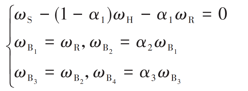
For the gear transmission system of flying vehicle, the meshing times of each gear in the system are different at the same time, so it is necessary to carry out kinematic analysis of the gear transmission system to keep the independent variables in the reliability model consistent. Assume that the absolute angular velocities of sun gear s, idler gear I, planetary gear P, ring gear R, planet carrier h, bevel gear B1, bevel gear B2, bevel gear B3 and bevel gear B4 are respectively ω S、 ω I、 ω P、 ω R、 ω H、 ω B1、 ω B2、 ω B3 and ω B4。 The kinematic equation of the transmission system is:
Where, α I is the characteristic parameter of the gear transmission system; α 1 is the ratio of the number of R teeth of the ring gear to the number of s teeth of the sun gear; α 2 is the ratio of the number of teeth of bevel gear B1 to the number of teeth of bevel gear B2; α 3 is the ratio of the number of teeth of bevel gear B3 to the number of teeth of bevel gear B4.
| Parts | Angular velocity | Number of meshing teeth in time t |
| Sun wheel s | ωS | ncωS t |
| Idler gear I | -ZSωS /ZI | ZSωS t/ZI |
| Planetary gear P | ZSωS /ZP | ZSωS t/ZP |
| Ring gear R (bevel gear B1) | ωS /α1 | ncωS t/α1 |
| Planet carrier H | 0 | – |
| Bevel gear B (bevel gear 2 B3) | α2ωS /α1 | α2ωS t/α1 |
| Bevel gear B4 | α2α3ωS /α1 | α2α3ωS /α1 |
The kinematic parameters of the gear transmission system can be obtained from the formula, as shown in the table. Where, “-” indicates that the rotation direction is opposite, and NC is the number of planetary gears, ω S is the input speed of the whole transmission system. In the unit time, the sun gear rotates 1 circle relative to the planet carrier, and the teeth on the sun gear will mesh with each planet gear. Therefore, in the unit time, the meshing number of the sun gear is equal to NC.

