
1 Introduction
Displacement spur gears have the advantages of long durability, stable operation, low noise and low vibration, and by effectively optimizing the displacement coefficient, the performance of displacement spur cylindrical gears can be equivalent to helical cylindrical gears, and can significantly reduce the manufacturing and maintenance costs of mechanical systems. Study the internal excitation of the gear system and dynamic characteristics play an important role in improving the transmission performance of the displacement gear system. Time-varying meshing stiffness (TVMS) is one of the main internal excitation sources that cause vibration and noise in gear transmission systems. Wang et al. proposed an analytical finite element method for calculating the meshing stiffness of gears, which not only considered the finite element calculation accuracy of complex foundation stiffness, but also considered the calculation speed of the gear tooth surface analysis method. Chen Siyu et al. proposed a method to simplify the equivalent gear into a cantilever beam for the meshing stiffness of the straight bevel gear, and analyzed the meshing stiffness of a single tooth by the energy method, and the effectiveness of the method was verified by the finite element method. Chen Guohui et al. established a time-varying meshing stiffness model of helical gears according to the change of gear meshing contact, and analyzed the vibration law of gear transmission system under different tooth widths and torques. Zhang Binsheng et al. analyzed the tooth surface of cracked gears On this basis, the influence of root crack depth on the meshing stiffness of spur gear was studied. Based on Hertz theory, Zhang Xin et al. studied the effects of different design tooth profile parameters on the pendulum of RV reducer The influence of the meshing stiffness of the wire needle teeth, and the finite element analysis method is used to verify the rationality of the theoretical model. Lin Tengjiao et al. established a model of the meshing stiffness of the tooth profile modification parameters on the herringbone gear based on the potential energy method, and analyzed the influence of different retract groove widths and modification parameters on the meshing stiffness The effectiveness of the model is verified by the finite element simulation model. Chen Siyu et al. put forward the calculation idea of the energy method for the calculation of the meshing stiffness of the spur cylindrical gear, and realized the rapid calculation of the meshing stiffness of the gear
It is clear that this method is effective. The above research mainly focuses on the TVMS algorithm and the dynamic characteristics of the gear transmission, but not on the geometrical characteristics of the displacement spur cylindrical gears and the dynamics are different. Based on this, an analytical model of displacement spur cylindrical gear transmission was established, and the influence of tooth profile displacement on time-varying meshing stiffness (TVMS) and dynamic characteristics was studied. The contributions of this study can be summarized as follows: 1) a new analytical model of TVMS for displacement spur gear is proposed and generated; 2) The influence of the tooth profile displacement of the spur cylindrical gear on the dynamic characteristics of TVMS was studied. 3) The influence of spur gear compound displacement on TVMS and its dynamic characteristics were discussed.
2 Time-varying meshing stiffness analysis model
Time-varying meshing stiffness (TVMS) is a typical periodic excitation source in a gear transmission system, which directly affects the operating performance and life of the transmission system. The design parameters directly affect the degree and strength of the time-varying stiffness excitation source. Therefore, it is essential to establish an effective time-varying meshing stiffness model to accurately predict the dynamic performance of spur gear transmission systems.
2.1 Stiffness calculation based on the potential energy method
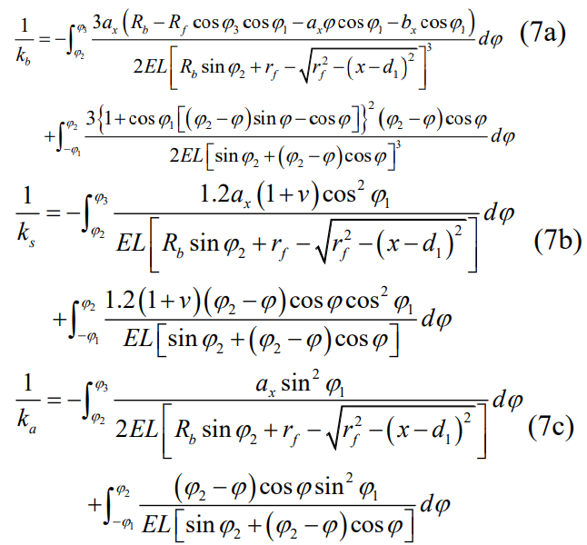
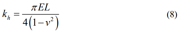
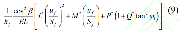
Based on the principle of the potential energy method, the gear teeth are simplified into a cantilever beam with variable cross-section, and the total potential energy is composed of Hertzian contact energy, bending energy, shear energy, axial compression energy and fillet base energy. According to elastic mechanics, these five potential energies can be written as:
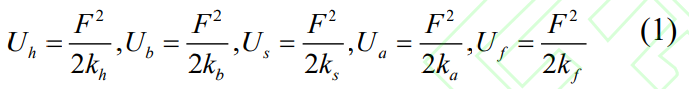
where F is the net force of the gear meshing on the contact surface of the meshing tooth pair. The total potential energy stored by a single gear can be described by the above component stiffness as:
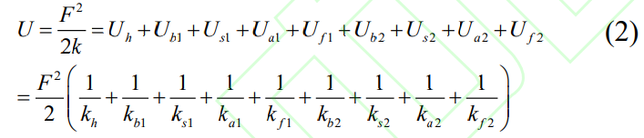
where k is the total meshing stiffness at mesh, and the subscripts 1 and 2 are the drive gear and driven gear, respectively. Therefore, the total TVMS of the meshing gear pair can be expressed as:
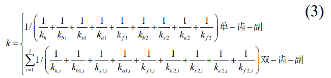
where the subscript i represents the ith meshing tooth. Considering different design parameters such as the number of teeth, modulus, and tip clearance coefficient, the tooth height can be determined according to the following two situations: 1) the root circle is smaller than the base circle; 2) The root circle is larger than the base circle. Tooth height can be calculated as:
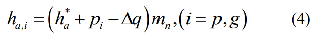
where the subscript i represents the pinion and gear, h∗ a is the tooth top coefficient, pi is the displacement coefficient, and Δq is the tooth top displacement coefficient, which can be expressed as Δq = pp + pg−q, where q is the center distance displacement coefficient.
2.1.1 Scenario 1
If the root circle is smaller than the base circle, the geometry of the teeth is as described in Figure 1. The tooth profile starts from the tooth top circle and ends at the tooth root circle, the tooth profile is the involute curve between the tooth top circle and the base circle, and the rest is the transition curve. Depending on the tooth geometry, the geometric parameters used to analyze the stiffness component can be expressed as:
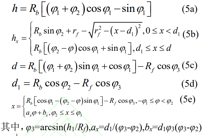
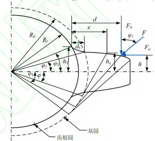
Fig.1 Tooth geometry of modified spur gear (case 1)
The geometric relationship between the base circle and the root circle transition curve is shown in Figure 2, and the transition curve can be described as a function of parameter h1, which can be expressed as:
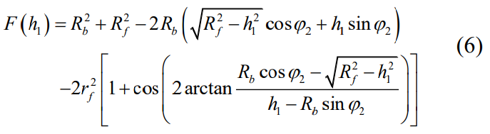
It can be seen that F(h1) is a nonlinear complex function of parameter h1, and given F(h1), the Newton-Raphson iterative algorithm is used to solve the equation.
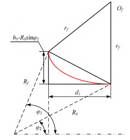
Fig.2 Geometric relationship of transition curve (case 1)
Axial compression, bending, and shear consisting of involutes and transition curves
The tangential stiffness can be expressed as:
2.1.2 Scenario 2
If the root circle is larger than the base circle, the geometry of the teeth is described in Figure 3. The tooth profile starts from the tooth apex circle to the root circle, where the tooth profile is the involute curve between the tooth apex circle and the root circle.
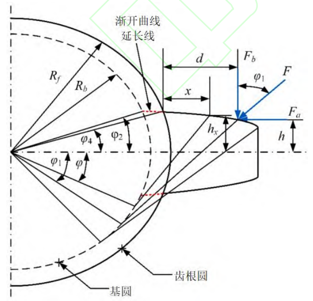
Fig.3 Tooth geometry of modified spur gear (case 2)
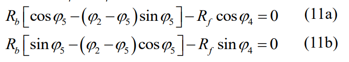
Similarly, bending, shear, and axial compression, which consist of involute curves The shrinkage stiffness can be calculated as:
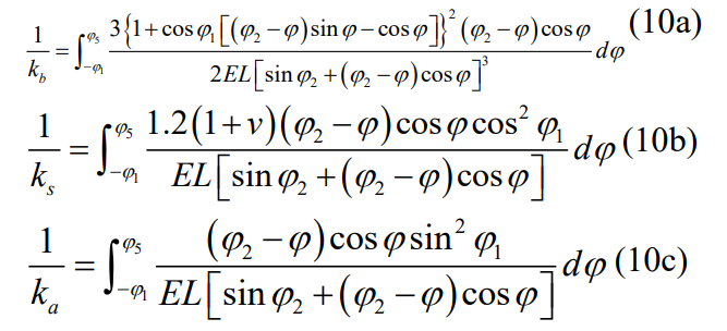
where φ4 and φ5 can be determined by solving the following coupling equation:
2.2 Geometric relationship analysis
For displacement gears and pinion sets with equal displacement coefficients, the pitch circle and base circle are constant. The geometric relationship of each is similar to that of equivalent standard spur and pinion sets. However, due to the incongruous variation of these circles, the geometry of the displacement gears with unequal displacement coefficients needs to be heavy New considerations. Especially in gear meshing, the pitch circle of the gear no longer coincides with the reference circle, so the position of the pure roll changes, which is different from the position of the standard spur gear. Based on the basic theory of displacement spur gears, the geometry at the beginning of gear meshing is shown in Figure 4.
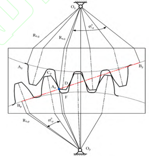
Fig.4 Geometric relationship between modified spur gear and pinion
At the beginning of the gear/pinion mesh, the AP point between the line of action and the top circle of the gear teeth is in contact. As the gearing progresses, the gear and pinion end up at the intersection of the line of action and the pinion tooth top circle Separate. Thus the angle φ1 of the pinion and gear can be written as:
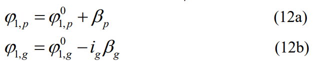
where ig is the gear ratio, the superscript 0 is the initial value of the angle, and the subscripts p and g are pinion and gear, respectively. The angle φ2 of pinion and gear can be expressed as:
where Np and Ng are the number of teeth of the pinion and gear, sp and sg are the tooth thickness of the pinion and gear, ep and eg are the difference between the number of links and the tooth thickness of the pinion and gear, φ0 is the reference pressure angle, and inv is the involute function. The mathematical expression for the initial value of the angle is:
where Rb,i is the radius of the base circle, Ra,g is the radius of the top circle of the upper tooth of the gear, and a’ is the center distance after displacement.
3 Research framework for displacement spur gears
In this section, the displacement spur cylindrical gears are examined according to the previously established TVMS model, and the framework is shown in Figure 5. Based on the vibration mode of the displacement spur cylindrical gear, the vibration response and statistical characteristics of the displacement spur cylindrical gear are extracted by using the centralized mass model.
Fig.5 Research framework of modified spur gear based on TVMS model
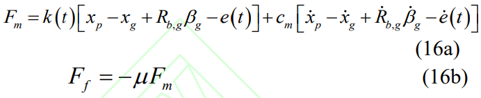
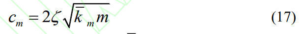
Figure 6 shows a six-degree-of-freedom dynamic model for a gear and pinion system, for spur gears, only motion and rotation along and perpendicular to the line of action are considered because the meshing stiffness affects the gear pair plane rather than the axial vibration. The shaft end is connected to the bearing, and the parallel spring damping device is adopted, and the governing equation of the power system can be written as:

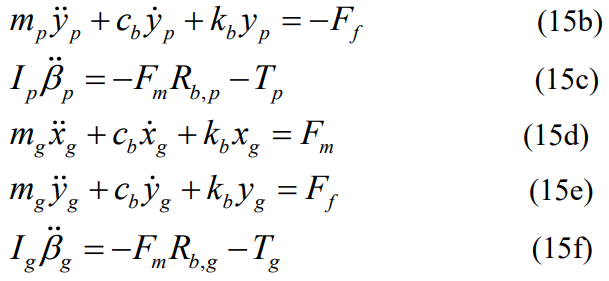
Among them, mp,g,Ip,g are the mass and moment of inertia of pinions and gears, cb and kb are the damping and stiffness of the bearing, Tp and Tg are driving torque and load torque, and Fm and Ff are meshing force and friction respectively, which can be expressed as:
where e(t) is the static transmission error and μ is the coefficient of friction. In addition, the meshing damping coefficient cm is calculated using the equivalent mass, damping ratio, and average meshing stiffness, which can be expressed as
where ζ is the damping ratio, mk is the average meshing stiffness, and m is the equivalent mass, which can be described by m = mpmg / (mp + mg). Therefore, since the other parameters are fixed, the damping ratio determines the meshing damping coefficient.
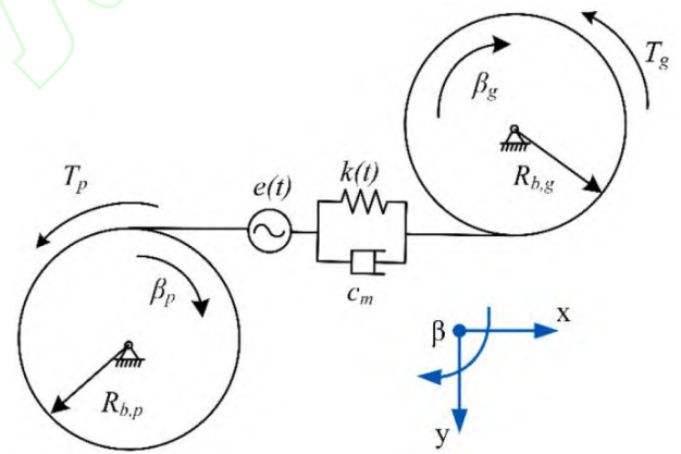
Fig.6 Dynamic model of gear and pinion
In order to analyze the influence of the damping ratio on the sensitivity of dynamic analysis, the ζ values of 0.07, 0.08, 0.09 and 0.1 were selected for simulation analysis. Thus, the dynamic transmission error (DTE) of the gear system can be expressed as a component DTE=xp−xg+Rb,pβp+Rb,gβg−e(t)。 , meshing gears and pinion sets The values of the design parameters are shown in Table 1.
In order to study the influence of tooth profile displacement, the dynamic simulation of gear systems with different displacement coefficients was carried out. The gearing characteristics reflect the main characteristics of the gear system interaction, the meshing force and the vibration acceleration
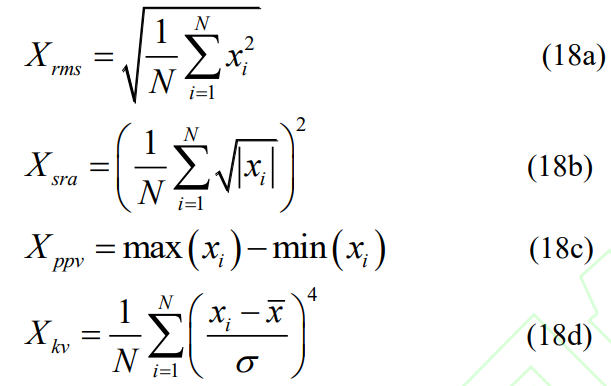
has a significant impact. In this study, the design parameters were analyzed using spectrum and statistical indicators. In order to systematically evaluate the influence of tooth profile displacement on the vibration of the gear system, four time-domain indicators were selected to describe the trend of vibration acceleration, namely root mean square (RMS), square root amplitude (SRA), peak-to-peak (PPV) and kurtosis (KV), which can be expressed as:
4 Case Study
4.1 Single-tooth displacement analysis
Before studying the TVMS and dynamic characteristics of displacement spur cylindrical gears, it is necessary to understand the effect of displacement factors on the stiffness of individual gear teeth. In this study, pinions were selected as the research object to study the effect of positive displacement. Here, we studied six displacement coefficients of 0, 0.1,Pinion tooth stiffness of 0.2, 0.3, 0.4, and 0.5. Figure 7 shows the stiffness of pinion teeth with different displacement factors. total The positive displacement coefficient makes the teeth more resistant to deformation caused by high stiffness. However, at the beginning of the meshing and at the end of the meshing, the effect of the displacement coefficient on the stiffness is different. To describe this effect more obviously, a ratio index relative to a standard spur cylindrical gear is proposed:

where ki is the stiffness of the ith tooth profile displacement pinion and k0 is the standard stiffness of the non-displaced pinion, i.e., pp = 0. Figure 8 shows the proportion of single-gear tooth stiffness under different displacement coefficients, and it can be seen that the larger the positive displacement coefficient, the steeper the stiffness curve during meshing. The larger the positive displacement coefficient, the higher the stiffness at the beginning of meshing and the lower the stiffness at the end of meshing.
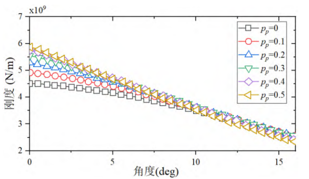
Fig. 7 Single Pinion Tooth Stiffness with Different Modification Coefficients
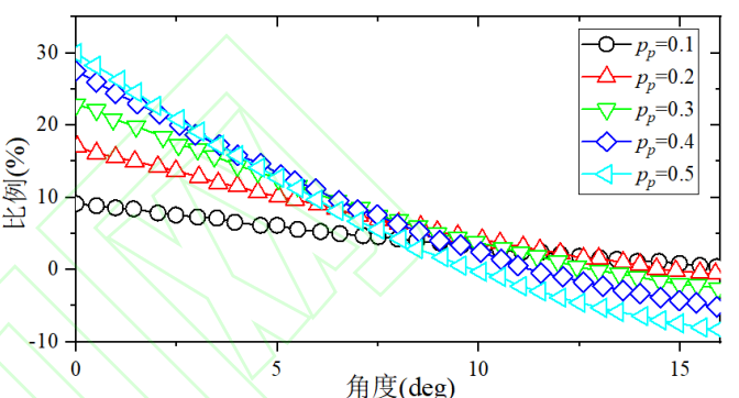
Fig.8 Comparison of stiffness ratio of single profile gear teeth
In order to analyze the influence of each parameter on the gear system in depth, the TVMS based on the positive coefficient of change was further analyzed. The TVMS results derived from the above analysis model are shown in Figure 9, and in order to more clearly describe the effects of gear meshing stiffness and contact ratio displacement coefficients, a range of 0◦ to is chosen 25◦ rotation angle pinion. From the perspective of comprehensive meshing stiffness, TVMS decreases with the increase of displacement coefficient. With the increase of the displacement coefficient, the change rate of TVMS also increases gradually. This illustrates that positive displacement is a very sensitive design that requires sensitivity analysis when selecting the desired parameter values.
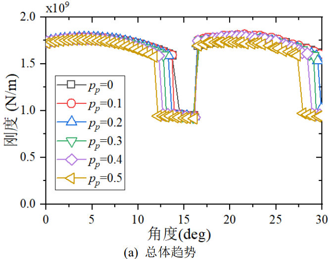
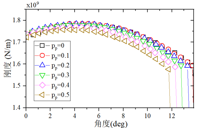
Fig.9 Comparison of TVMS with Different Modification Coefficients
Figure 10 shows the mean change and standard deviation of the TVMS at positive displacement. The mean and standard deviation can describe the average level and the degree of oscillation of the TVMS, respectively, and the change and displacement coefficients of these two indicators show a nonlinear relationship, respectively. The average decreases slowly with a slight positive displacement and accelerates with a large positive variation. At the same time, the standard deviation increases dramatically with a slight positive displacement and slows down with a larger positive displacement.
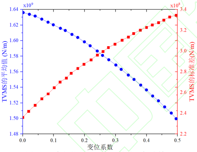
Fig.10 Mean Value and Standard Deviation of TVMS for the Positive Shifts
In order to quantitatively analyze the influence of positive displacement, statistical indicators with displacement coefficients of 0, 0.1, 0.2, 0.3, 0.4 and 0.5 under different damping ratios were extracted. The ratio comparison with a standard spur gear is shown in Figure 11 and is OK It can be seen that with the increase of the displacement coefficient, except for the PPV when the damping ratio is 0.07, the other indicators show a monotonic growth trend. This indicates that positive displacement increases the vibration of the gear pair, while KV is negative in the range of small displacement coefficients. The results show that a slight displacement coefficient decreases the peak, while the more Large displacement factors increase the peaks, and the meshing damping coefficient can be found Insensitive to statistical indicators.
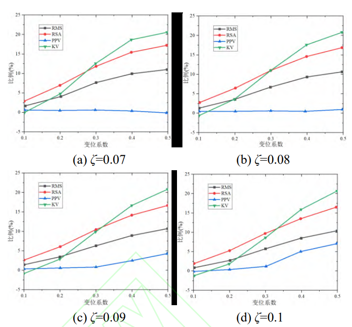
Fig.11 Statistical Indicators of DTE for the Positive Shifts
4.1.2 Negative displacement analysis
In order to balance the fatigue life of the gear and the pinion pair, the negative displacement gear is generally used in the engineering to achieve the same life design. In this study, six displacement coefficient values were selected with 0, -0.1, -0.2, -0.3, and -0.4, respectively and -0.5. Figure 12 shows the stiffness of the gear per tooth at different displacement factor values, which make the gear softer than a standard spur cylindrical gear. As with positive displacement, the effect of the displacement coefficient on stiffness is different at the beginning and end stages of meshing. At the beginning of meshing, the stiffness loss is small, and gradually increases as the meshing progresses.
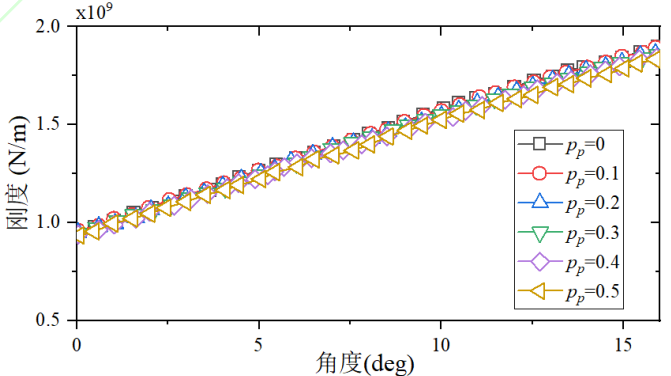
Fig. 12 Single Gear Tooth Stiffness on Gear with Different Modification Coefficient Values
Figure 13 shows the rate of change of the stiffness of the single gear tooth at different displacement factor values. Unlike positive displacement, the curves representing the change in meshing stiffness are all in their respective parabolic curves and do not cross. The greatest loss of stiffness can be found in the middle of the mesh. With the decrease of the displacement coefficient The smaller (real value), the more curved the rate of change becomes.
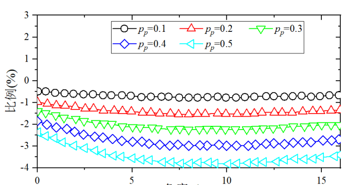
Fig.13 Rate of Change of Single Gear Tooth Stiffness
For an in-depth analysis of the impact of each parameter on the gear system, the TVMS results based on the above analysis model are shown in Figure 14. In order to more clearly describe the effect of gear meshing stiffness and contact ratio displacement coefficient, a rotation angle range of 0 was still chosen
◦ to 25◦ pinion. The TVMS of the spur gear based on the negative displacement design is smaller than that of the standard gear in the initial stage of meshing, and the comprehensive meshing stiffness gradually increases with the meshing progress. In the end, the TVMS with a smaller displacement factor will outperform the larger displacement factor TVMS。 It can also be seen that the TVM with a small displacement coefficient has a higher contact ratio, so the negative displacement can improve the smoothness and continuity of the transmission.
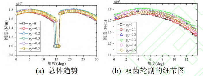
Fig.14 Comparison of TVMS with Different Modification Coefficients
Figure 15 shows the mean and standard deviation of TVMS at negative displacement. The variation of these two indicators is approximately linear with the displacement coefficient. As the displacement coefficient decreases (real value), the mean gradually increases, while the standard deviation decreases regularly.
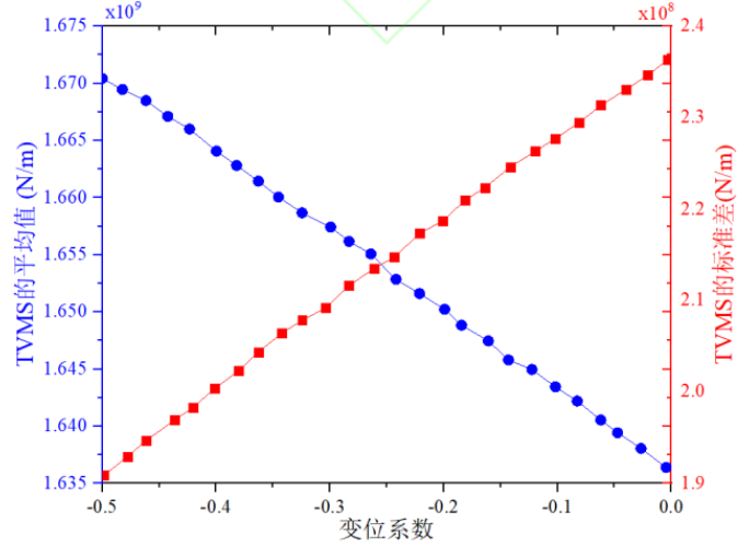
Fig.15 Mean Value and Standard Deviation of TVMS for the Negative Shifts
In order to quantitatively analyze the effect of negative displacement, the statistical indicators of DTE were extracted, and the displacement coefficients were 0, -0.1, -0.2, -0.3, -0.4 and -0.5 under different damping ratios. Figure 16 shows a proportional comparison with a standard spur gear, and the results show that all indicators change monotonically as the displacement coefficient decreases. RMS and RSA showed a downward trend, indicating that negative displacement can dampen the vibration of the gear pair. In addition, KV improved slowly, but PPV did not change significantly.
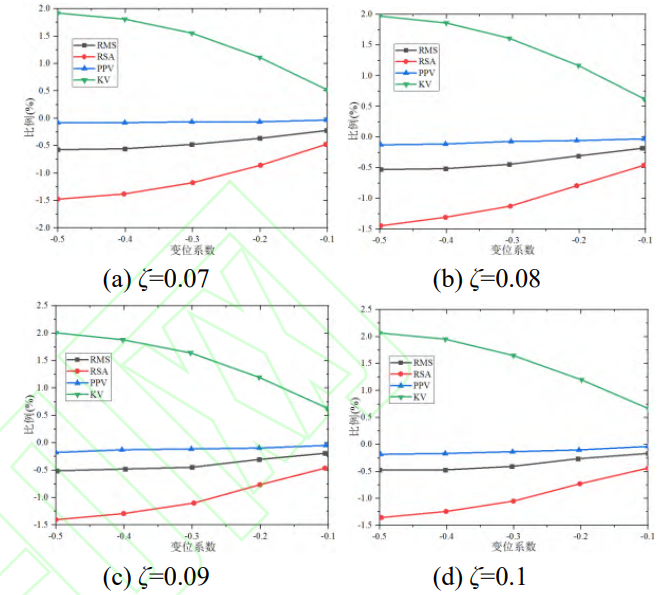
Fig.16 Statistical Indicators of DTE for the Negative Shifts
4.2 Compound displacement analysis
In reality, tooth profile transformation is commonly used to design the mechanical properties of gears and pinion pairs. S0 gearing and S-gearing are two forms of composite modification of displacement spur cylindrical gears[16]. The total coefficient of displacement of the former is zero, and the total coefficient of displacement of the latter is non-zero. Figure 17 depicts the TVMS curves for different composite displacement designs, with the first and second groups being S-gears with positive total displacement coefficients, the third and fourth groups being S-gears with negative total displacement coefficients, the fifth group being s0 gears, and the sixth group of standard spur gears. pp = 0.4, pg = 0.1 in group 1, group 2 pp = 0.2, pg = 0.1, group 2, pp = 0.1, pg = -0.6 in group 3; fourth pp = 0.1 and pg = -0.4 in group 4 and pp = 0.1 in group 5 pg=-0.1, named group 5, and group 6, pp = 0, pg = 0, named
for group 6. As can be seen from the graph, a negative total displacement coefficient increases the contact ratio and meshing stiffness, while a positive total displacement coefficient can significantly reduce the contact ratio and meshing stiffness, and it can be seen that the s0 gear has a relatively small effect on the TVMS.
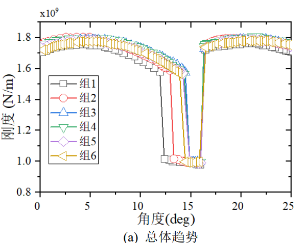
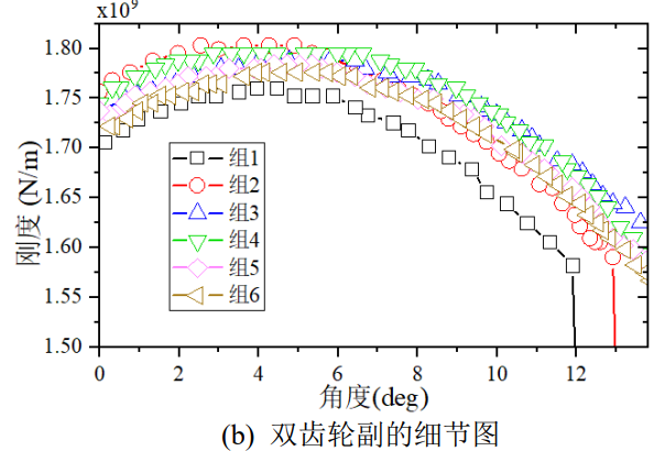
Fig.17 Comparisons of TVMS with Different Compound Shifts
Figure 18 shows the mean and standard deviation of TVMS for different composite displacements. When the total displacement coefficient is negative, the mean value of TVMS is higher, while the standard deviation shows an opposite trend. Average of different total coefficient of displacement
The effect is more dispersed at the pinion coefficient and closer at the pinion coefficient.
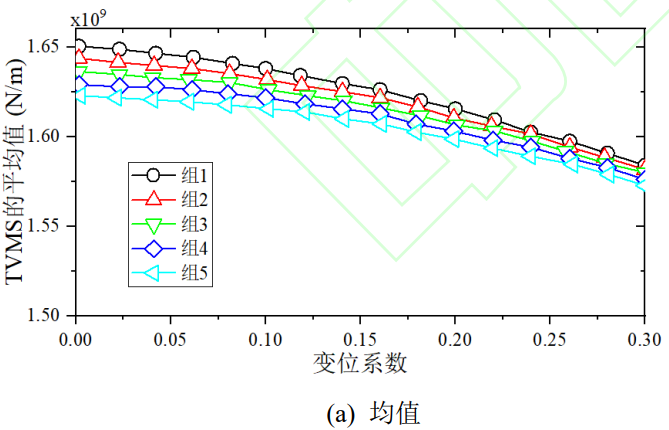
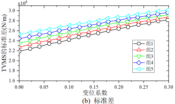
Fig.18 Mean Value and Standard Deviation of TVMS for the Compound Shifts
Fig. 19 shows the changes of the statistical indexes of composite displacement DTE under different damping ratios. Similar to the spectrum, the index of positive compound displacement is higher than that of negative compound displacement, and the RSA difference even reaches about 15%. The KV curve, on the other hand, appears as a polyline, indicating that the S-gearing makes the time-domain waveform of the gear system steeper. There is a certain difference between the statistical indicators of the s0 gear and the standard spur gear, which is mainly due to the fact that the displacement coefficient is numerically equal, but the sign is opposite, so that the pinion and gear displacement are different.
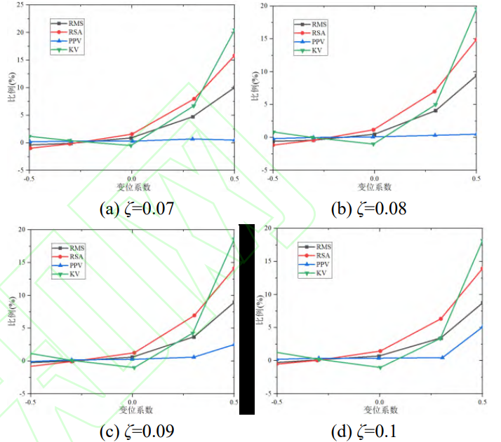
Fig.19 Statistical Indicators of DTE for the Compound Shifts
5 Conclusion
In this study, an analysis model of displacement spur cylindrical gear transmission was established, and the influence of the tooth profile displacement spur gear on the operation performance of the gear system was discussed. In this model, the dynamic characteristics of the spur cylindrical gear system with the pinion angle as the independent variable can be directly obtained, and two different tooth profile displacement geometries are considered. According to the established analysis model, the influence of contour offset on TVMS and dynamic characteristics is studied by numerical simulation method under the given evaluation method, and the results show that the positive displacement of a single tooth profile will reduce the stiffness and TVMS of the gear teeth, and the negative displacement of a single tooth profile can be to improve the stiffness and TVMS of the gear teeth. For the compound displacement, the S-gear transmission with positive compound displacement can reduce the TVMS but exacerbate the vibration of the gear system, the S-gear transmission with the negative compound displacement will cause the TVMS to increase and significantly reduce the vibration, and the s0 gear displacement has less effect on the time-varying meshing stiffness (TVMS) but has a greater effect on the dynamic characteristics.