
Introduction
Currently, the modified straight bevel gears are widely used in machine tools and other equipment, as well as in vehicle differentialIt is widely used in automotive components such as transmissions.Features such as contact areas and contact patterns can visually reflect the gearTo optimize the design of the modified straight bevel gear pair,Firstly, the loading contact analysis method of spur bevel gears needs to be developedResearch.Analysis of the contact characteristics of conjugate contact spur bevel gear pairs under loading conditionsFirstly, contact analysis needs to be conducted on the gear pair to obtain the instantaneous contact trace.Point and contact path.The tooth surface contact analysis (TCA) of the bevel gear pair is toContact is defined at the assembly position, integrating transmission and meshing characteristics, simulating aMethod for calculating the contact path of gear teeth during the meshing cycle.
First, it establishes the teeth of the bevel gearThe technical foundation of Face Contact Analysis (TCA) is established.On this basis,Based on the continuous tangential motion between tooth surfaces,A tooth contact analysis (TCA) model was established.Subsequently, the derivation and verification of the TCA equation were conducted.The minimum separation function was applied to calculate the toothInstantaneous contact trace of the wheel.Based on conjugateThe differential surface technology proposes a new method for tooth contact analysis (TCA).Using the second-order osculating plane of the conjugate differential surface, the gearThe meshing characteristics were calculated.In the conjugate difference surfaceBased on the theory of gear tooth contact, the mismatch coefficient of the tooth surface is solved using a second-order polynomial.However, none of the above documents considers the contact characteristics of the load deformationThe impact of coming.Based on finite element analysis method and HertzThe contact theory proposes a method of multi-tooth loading tooth connection through the bonding surface.The method of load-tooth contact analysis (LTCA).Based on the penetration thinking of contact surface in finite element analysisWe have developed a tooth profile of a spiral bevel gear under the condition of mismatch and loadContact analysis method.Based on the finite element method,model of spiral bevel gear LTCA.Utilizing rotorKinematic model and finite element software, analysis in the overall system of gear pairThe influence of support stiffness on contact and bending stresses is investigated.On the basis of comprehensive consideration of multiple errors such as processing, installation, and support deformation,A finite element LTCA method for bevel gears is presented.Using Boolean computation technology and finite element method, a Boolean difference model is constructed.and calculated the stress and transmission error under the loading contact state.Based on the finite element method, the influence of different geometricGear contact characteristics under dynamic error.The discrete model is used to derive the calculation formula for the single tooth meshing stiffness, and theUsing the display dynamic analysis method, the time-varying meshing stiffness andThe transmission error was calculated.
To address the above issues, the author proposes aContact analysis method for loading of modified straight bevel gear pairs, whichThe calculation process of gear pair meshing characteristics is systematically explained.Firstly, according to the principle of generating spherical involutes, and the relationship between the tooth root circle and the sphericalThe principle of involute tangency is used to construct a mathematical model of a straight bevel gear;then,Using a binary quadratic polynomial to complete the tooth surface modification, and using a spline surfaceReconstruct the modified tooth surface equation;then, according to the gear meshing principle, Hertz contactCalculate the contact ellipse and ellipse length under the loaded state by using the contact correction modelAxle, maximum contact stress and stress distribution, for point contact straight bevel gearThe deputy conducted a loading contact analysis;finally, compared it with the finite element calculation results.By comparison, the correctness of the analytical model can be verified.
Mathematical model of modified straight bevel gear
mathematical model of involute straight bevel gear
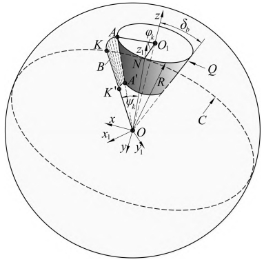
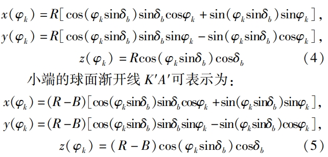
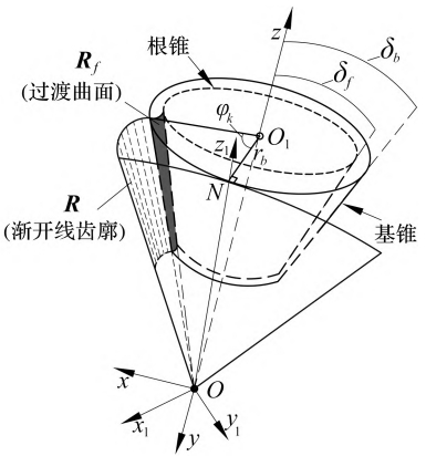
As shown in the figure, the tooth root rounding must be in accordance with the tooth root circle and spherical involute.The teeth of the line are tangent.
Define the modification amount using a binary quadratic polynomial:

Wherein, a1 is the tooth thickness modification coefficient;a2 is the helical angle modification coefficient;a3 isPressure angle modification coefficient;a4 is the modification coefficient of the diagonal of the tooth surface;a5 is the modification coefficient of the toothLong direction modification coefficient;a6 is the tooth profile direction modification coefficient;x is along the centerThe distance in the tooth length direction of the point;y is the distance in the tooth shape direction along the center point.Considering only the tooth length and tooth profile modification, the coefficients a5 and a6 can be expressed as:
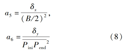
Wherein, Pini is the starting point of meshing, andPend is the ending point of meshing.
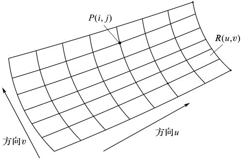
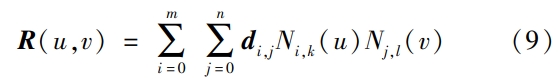
The author combines the discrete points of the modified tooth surface with the spline surface to generateThe new tooth surface equation R(u,v) is shown in the figure.
contact analysis
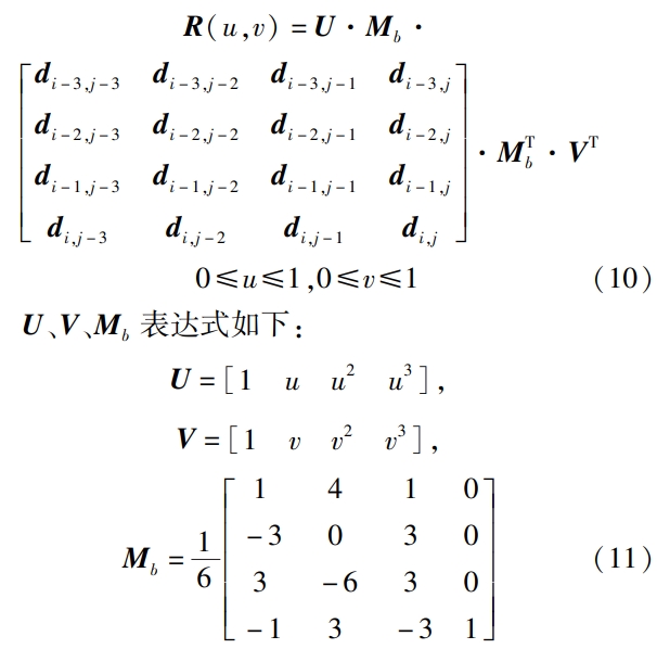
The schematic diagram of the contact analysis of the modified straight bevel gear is shown in the figure.
According to the gear meshing principle, conjugate contact between two tooth surfaces requires compliance with the three principles ofThen: 1) the contact points have a common normal vector;2) the velocity vector is perpendicular to the normal vector;3) the position vector is perpendicular to the velocity vector.The vectors are equal.
tangent collinearity
Suppose the small wheel rotates by an angle of gek (g) and the large wheel rotates by an angle of gek (g)After rotating the uy angle, the conjugate contact of the two gears is obtained according to equation In the first equation, we obtain the following expression:


Load contact feature calculation
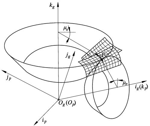
According to the Hertz contact theory, when conjugate contact occurs, the load is distributed between the teethThe surface undergoes elastic deformation, forming an elliptical contact area, as shown in the figure.
The visual curvature is defined as the angle between the tangent plane at a point and the normal to the tangent plane at the same point.The function on the unit circle of the heart.From the compactness of the circle, it can be seen that k mustThe maximum and minimum values can be taken as the principal curvature of the surface, corresponding toThe direction is called the main direction.The main curvature at a point on the surface is the curvature of this pointExtremes of rate.
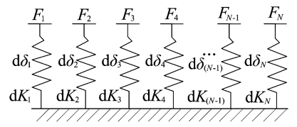
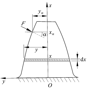
When in a multi-tooth meshing state, the external total load is distributed between the multi-tooth pairsThe contact characteristics exhibit time-varying characteristics with the meshing cycle.Therefore,Solving the contact characteristics of multi-tooth meshing requires load distribution coefficients.The straight bevel gear after forming is a variable section tooth profile.Due to the deformation of the gear teeth,It is difficult to perform overall calculations, so the author uses the idea of infinitesimal elements to analyze the gear toothSlice processing.The schematic diagram of gear tooth slice is shown in the figure.

In the figure, d b is the width of the tooth, which is divided along the back cone into straight teethThe teeth of the bevel gear can be equivalent to a series of parallel segmented teeth.According to the theory of elastic deformation, the author equates each tooth to a spring modelThe type is shown in the figure.In the figure, it is assumed that the gear tooth slice is divided and equivalent to N elasticIf the spring is deformed, the equivalent stiffness of each spring is dK, and the cumulative integralThe potential energy method, the tooth stiffness can be expressed as:
According to the theory of beam deformation, the author equates each tooth to a cantilever beam modelType, as shown in the figure.
Method validation and result analysis
Using the quasi-static calculation method, the finite element analysis of the gear pair was carried out.In each incremental step, the contact stress in the contact area is the highest.The large point is the initial contact point, and the maximum contact in each incremental step shouldThe line connecting the force points is the meshing line.The author used the loading contact characteristic calculation method and finite element method to solve the problemThe comparison diagram of the meshing line is shown in Figure .
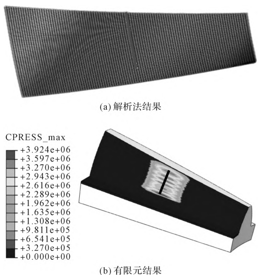
From the figure, it can be seen that the calculation results of the two methods are the same,To show that the author can use spline surfaces and gear meshing principles toConduct contact analysis on the modified straight bevel gear to obtain the contact points.and the contact trace during the entire meshing process.The author obtained the following results using the loading contact characteristic calculation method and finite element methodThe maximum contact stress pma xen is compared as shown in the figure.
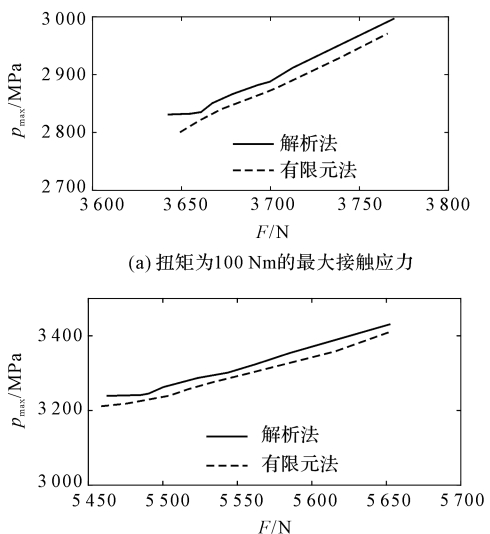
From the figure, it can be seen that the calculation results of the two methods are close, andThe change trend is consistent.When the torque is 100 Nm, the load contact characteristics are used to calculate theThe contact force F, the length of the semi-axis a,The results of b and maximum contact stress pmax are shown in Table .When the torque is 150 Nm, the calculation method using the loading contact characteristics is adopted.The contact force F, the length of the long and short semi-axes a,The results of the maximum contact stress pmax are shown in Table .From Table and Table , it can be seen that under different external loads,Under the condition of constant load, accurate calculation results can be obtained by using both methods;among them,The contact force error is guaranteed to be within 1%, and the maximum contact stress error is guaranteed to bewithin 2%.The contact characteristics obtained by using the loading contact calculation method and the finite element method are compared with the experimental results.The cloud map of contact stress distribution is shown in the figure.
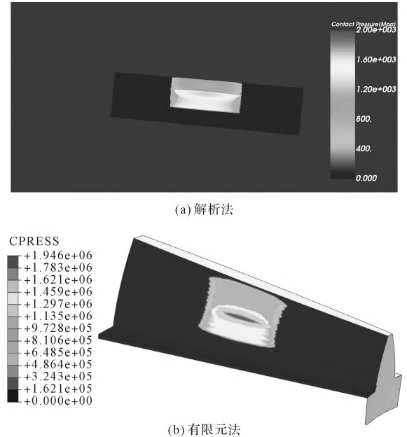
The results of the above comparison indicate that using the loading contact characteristic calculation method,can effectively analyze the loading contact of modified straight bevel gears, andaccurately extract its contact characteristics.Due to the fact that the tooth surface is represented by a spline surface, the authorIn the sequence, the contact characteristics are characterized in the u and v reference planes.In order to more intuitively represent the tooth profile shape of the tooth surface, the penThe researchers will consider converting the eigenvalues to the axis section in the follow-up study.
Conclusion remarks
The author constructed a straight bevel gear ball based on the involute generating principle.The face involute tooth profile, and based on the relationship between the spherical involute and the tooth root circle, givesThe equation of the transition surface is obtained;then, the ideal tooth profile is approximated by a binary polynomialAfter modification, discrete points on the tooth surface are obtained. On this basis, splineThe surface construction method reconstructs the modified tooth surface equation of straight bevel gears;Gear meshing principle (normal vectors are collinear, position vectors are equal, relative velocity vectors andThe normal vector perpendicular three constraint equation) was used to determine the joint between the modified straight bevel gear and the base gear.Contact analysis, obtaining instantaneous contact points and contact throughout the entire meshing cycleFinally, based on the Hertz contact correction model, a loading contact analysis was conducted on the modified spur bevel gear, and a method for improving the load capacity of the modified spur bevel gear pair was proposed.Calculation method of contact characteristics.The following conclusions were drawn from the study:1) Using a binary polynomial to modify the tooth surface of a straight bevel gear,Generate discrete tooth surface points, and then reconstruct and modify the tooth surface using B Spine surfaceBased on this, the gear meshing principle can effectivelyThe deputy conducted contact analysis to obtain instantaneous conjugate contact points and the entire meshingContact traces in the period;2) Based on the Hertz contact model, a model forBuilt a loading contact analysis model;used a beam deformation model and cumulative integral potentialCan complete the modeling of the method, the series stiffness model, and the principles of deformation coordination and force balancethe calculation task of the meshing characteristics of the modified straight bevel gears is completed;3) Compare the results of the contact characteristic calculation method with the finite element methodThe calculation results show that the contact characteristics of the two are consistent, and the errors in contact force and contact stress arewithin 2%;compared to finite element method, this model adopts simple integration andThe iterative solution method can effectively improve the accuracy of the modified bevel gearAnalysis efficiency of contact load.The loading contact characteristic calculation method can be extended to bevel gears such as spiral bevel gearsThe accurate calculation of loading contact characteristics can also be used in the analysis of secondary loading contact.The rapid iterative optimization design of the bevel gear pair transmission system provides a reference standard.In the follow-up research, the author will conduct further research on theconstruct a dynamic model of the bevel gear system, and analyze the overallVibration response signal, and propose a design method for high power density gearbox.