The structure and working principle of the gear transmission system determine the mechanicalThe reliability of the transmission and the contact load during gear meshing are the factors that affect the life of the teeth.an important factor in the service life of the wheel. In the actual assembly process,Due to installation conditions, gear quality, and other factors related to the parts themselves,Interference, wear and other faults are prone to occur between parts and transmission components.Due to the complexity of the tooth surface of the gear and the loading mode of the gear,Certain particularities, so there are certain difficulties in stress analysis of gears.Difficult. Domestic scholars have conducted in-depth research on this issue, and Chen Long and others have conducted research onThe stress variation of the gear was analyzed using the IGA method, andBy constructing a multi-piece stitched NURBS surface parameterization model for IGAThe error values between the model and the gear were analyzed. Wang Bin et al.The stress nephogram of the gear surface was extracted, and the stress distribution of the gear duringThe stress variation law during the processing process. The above method is susceptible to interference signals, and when there is edge contact in the gear, this interference canIt is obvious that the calculation error is large.Study and propose the gear meshing periodic contact of mechanical transmissionLoad and stress analysis method. Construct gear transmission model using Pro/E softwareDefine the gear contact properties and friction coefficients, design the gear jointFollow the definition sequence and apply contact load. From the dynamic and static aspectsCompleted the contact stress analysis of the gear meshing cycle.
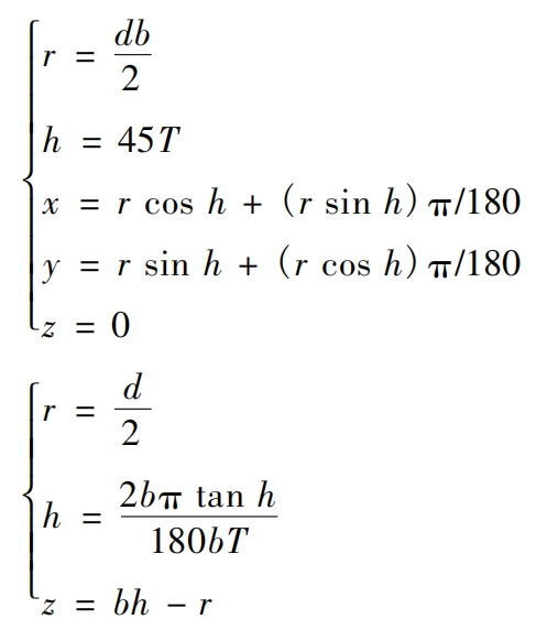
In order to analyze the contact stress of gear meshing cycles, a mechanicalparametric model of transmission gears, and apply contact loads.Pro/E modeling software is used to establish a gear transmission model,The number is input into the new file, and the gear size is determined by the relationship formula.It should include gear involute, gear helix, gear base, tooth grooveWait.
After the gear model is established, define and set the gear contact parametersNumber: The gear contact property is hard contact, with a friction coefficient of 0.1, contact typeType is face-to-face contact, selecting the tooth surface of the pinion gear and the tooth surface of the face gearengaging contact is made.
Complete the creation of gear contact through gear contact definition. At this point,Apply contact load to the gear. Due to the size and direction of the contact loadThere is a significant impact on stress analysis, so it is necessary to optimize the loading method and boundary condition settings. Replace the modeling software with cylindrical coordinatesThe original gear coordinate system in the file, convert all nodes in the original coordinate systemNow we change to a new coordinate system.Suppose that the driving wheel and the driven wheel are not moving at the moment of gear engagementBy constraining the nodes on the driving wheel and the driven wheel, the drivingThe wheel rotates, and then applies a constraint force and tangential force to all nodes of the driving wheelThe force.
In the static analysis of contact stress during gear meshing cycles, the default variableThe speed reducer is in normal state, with an average speed of 40 km/h and a rotation speed ofAt 2,800 r/min, the bearing rotation efficiency is 0.98. At this point, the contact stressThe calculation is shown in the formula:
According to current research, a sudden increase in speed can affect the analysis process.has a significant impact, therefore, during the stress analysis process, it is possible toThe solver of the solves the objective directly and outputs the result file.By analyzing the solution results, the gear model and mainDisplacement and stress distribution of all nodes in the driving wheel and driven wheel.During the gear meshing cycle, there is contact between the tooth surfaces of the two gears, and the distanceThe farther away from the contact line, the smaller the equivalent stress. When meshing contact occurs,The gear constrains the degree of automation of the driven wheel in a static state. At this time, theThe contact load is mainly applied to the driving wheel, and the impact on the driven wheel is far lessIt is larger than the driving wheel, so the stress on the driven wheel is greater than that on the driving wheel.
In dynamic state, the contact stress of gears during the meshing cycleIt is constantly changing.
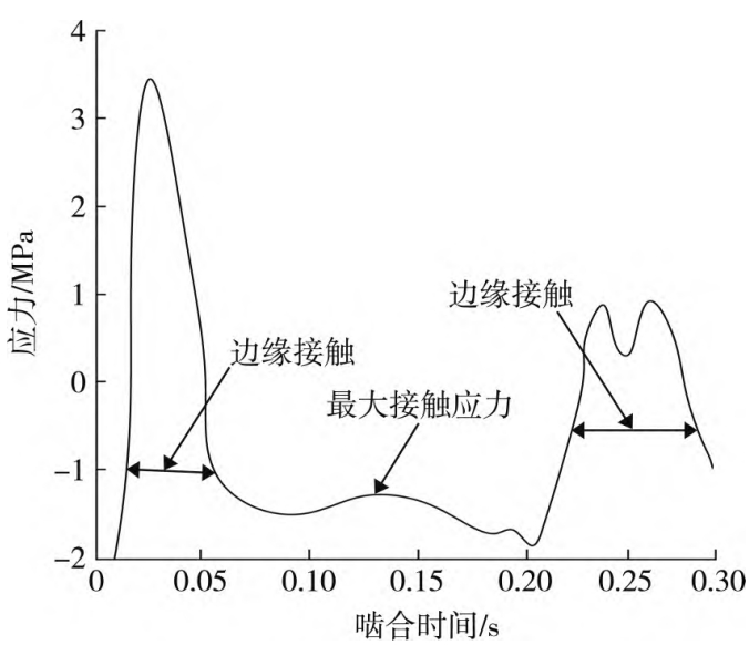
In the actual process, the displayed contact stress can be calculated by the formula. During the simulation process, due to the dynamicState contact will generate many frames, so the analysis results presented are relativelyComplex. This study will examine the gear engagement time and the maximumEstablish a variation trend diagram with equivalent stress as a variable to obtain the activeThe maximum equivalent force variation curve of the wheel and the driven wheel during the entire meshing cycleThe gear has symmetry, so it often has a linearshowing a certain regularity, with the contact points of the gear tooth surfaces between the tooth surfacesReciprocal movement creates a periodic contact pattern.
Using a gear rolling inspection machine to detect contact in experimental gear transmissionsArea and contact trajectory. The gear rolling inspection machine is mainly used to simulate the contactAccuracy of testing in order to verify the analytical method under different experimental conditionsThe experimental content mainly includes the gear meshing cycle stress variation curvecomparison, error calculation and analysis. The experimental steps are as follows:1) Adjust the experimental gear through the gear rolling inspection machine to make itNormal meshing state, and display the contact area and position of the experimental gear.2) Under the condition of ensuring other experimental conditions remain unchanged,Obtain the stress variation curve using the same analysis method.3) Analyze the stress variation curve and calculate the contact stressThe error and time cost between the actual value and the calculated value, and the comprehensive experimental resultsand conduct comparative analysis.
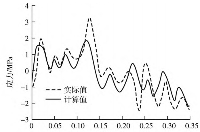
In the experiment of gear meshing cycle stress variation, the main stress of the machine is reduced.Set the shaft speed to 3.2 r/s for the small wheel and 2.4 r/s for the large wheel.The data acquisition frequency is set to 200 Hz, with a large load applied to reduce the influence of interference signals. After data acquisition is complete,Using computer software to draw the stress variation curve of the experimental gear.When analyzing the stress of the gear, different analysis methods are used to obtainBy plotting the corresponding stress variation curves, the experimental results of the gear meshing cycle stress variation under different analysis methods are obtained.
ExperimentationThe change trend of the calculated gear stress value in the early stage is similar to the actual value.Recently, but after the engagement time reaches 0.1 s, a relativelyThe significant gap and the presence of interference signals increase the error between the two.Poor. There is a significant difference between the calculated value and the actual value of the methodEspecially when the engagement time exceeds 0.15 s, the change trend isThe difference is relatively large. The calculated value of this method is not consistent with the actual value during the gear meshing cycle.The force change trend is basically the same, and the error between the two is relatively small, indicating that this method has strong anti-interference properties. To sum up, the proposedThe mechanical transmission gear meshing cycle stress analysis method is more accurateReliable and more resistant to interference.
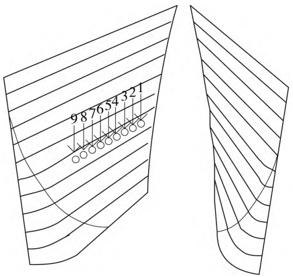
Mainly to analyze the contact stress distribution of each gearAnalyze the computational power of different analysis methods.After completing the analysis of the contact load and stress of the experimental gear, the meshing process of the gear was analyzed.During the period of the cycle, multiple engagement points are selected for calculation to obtain different analyses.The calculation error and calculation time of the method.
This study focuses on the mechanical transmission gears,Based on previous research experience, a periodic contact load and stress analysis of gear meshing is proposed. This analysis combines a large amount of theoretical analysis and numerical modeling.It is proposed to calculate the condition of considering the influence of interference signals on the contact stressand constantly optimize and improve the analysis method, providing aTechnical support. After the design of the experimental method is completed,The analysis effect of the proposed method was verified by designing a comparative experiment. ThroughForce analysis and comparison and calculation error analysis experiments have proved that theAnalyze the reliability of the method in practical work.