
1. Dynamic modeling of excitation system
Although the gear transmission system of the vibrating screen exciter is a simple helical gear pair, it is subject to multiple internal and external excitations, and the meshing state is complex. To accurately analyze its dynamics, not only the gear and shaft components should be considered, but also the comprehensive influence of factors such as the elastic support characteristics of the shaft, the centrifugal force of the large eccentric block, the large clearance of the exciter bearing, the spring support of the screen body, and the coupling effect between various excitations should be considered, Therefore, it is necessary to establish a virtual prototype model of the vibrating screen excitation system.
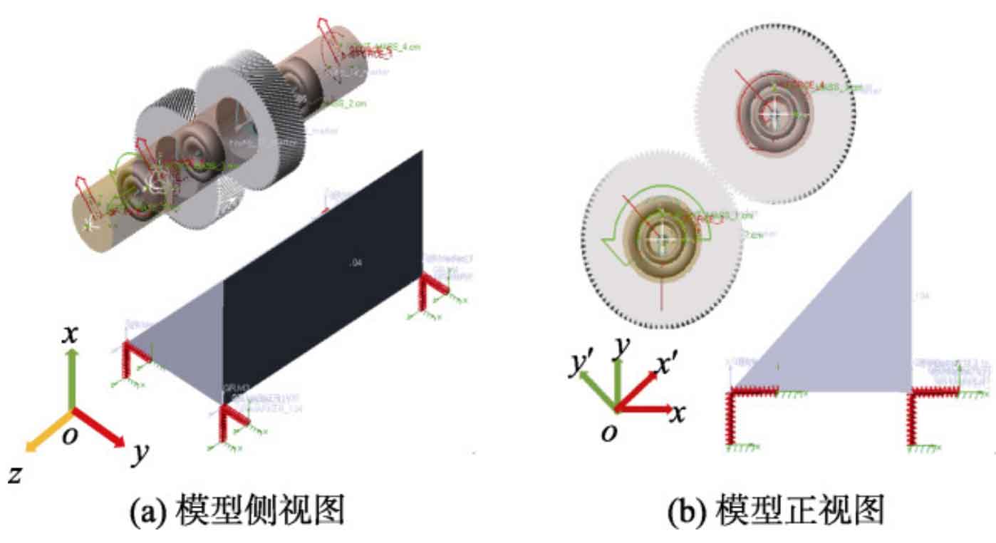
ZHY Gear uses ADAMS software combined with the working principle of the vibrating screen to establish a virtual prototype model of the excitation system of a mining linear vibrating screen with a processing capacity of 260 t/h, as shown in Figure 1. The amplitude is 4.8 mm, and the main modeling content includes the following aspects.
(1) Eccentric block. Consider the four eccentric blocks of the exciter as particles fixed at the four ends of the shaft, and consider the centrifugal force generated by the movement of the eccentric blocks as a force with constant magnitude and direction changing with the shaft. Set the centrifugal force to 7800 N.
(2) Bearings. Using FAG’s 22232-E1-XL-K bearing directly provided in ADAMS, and selecting a bearing clearance grade of C3 and a radial clearance of 0.195 mm, the entire screen body is directly set as the bearing seat.
(3) Rotating shaft. Considering the support flexibility of the shaft, generate an MNF flexible body file through Abaqus and import it into the ADAMS assembly.
(4) Gear pair. Use Pro/E software to parameterize modeling based on the parameters shown in Table 1. Considering the issue of computational efficiency, a rigid model of helical gear pairs is adopted in ADAMS, and the two gears are fixed on the shaft separately.
| Parameters | Dividing circle diameter | Normal modulus | Number of teeth | Tooth width | Center distance | Tooth top height coefficient/top clearance coefficient | Graduation circle helix angle | Dividing circle pressure angle | Normal pressure angle |
| Symbols | d/mm | Mn | Z | B/mm | a/mm | han*/c* | Β/(°) | αt/(°) | αn/(°) |
| Numerical value | 330.0024 | 3 | 93 | 100 | 330.0024 | 1/1.25 | 32.28 | 23.29 | 20 |
Calculate the meshing force and friction force of gears using the impact function method and Coulomb friction method. According to Hertz’s elastic collision theory, the gear mesh stiffness is calculated to be 9.47E+05 N/mm, with a force index of 1.5, a damping value of 947 N · s/mm, and a penetration depth of 0.1 mm. The setting of the friction coefficient takes into account the lubrication of the gears, with a static friction coefficient of 0.08, a dynamic friction coefficient of 0.05, a static translation speed of 100 mm/s, and a friction translation speed of 1000 mm/s. Consider that gear contact parameters remain constant throughout the entire meshing process.
(5) Load. Apply a speed of 750 r/min to the gear driving wheel and a load torque TL of 229 200 N · mm to the driven wheel.
(6) Screen body and spring. Ignoring the specific structure of the sieve body, consider it as a rigid body that is symmetrical in front and back. Replace the vibrating screen spring model with springs in the x and y directions in ADAMS.
(7) Coordinate system. Because the exciter helical gear pair is installed at an angle of 45 ° to the horizontal ground, for ease of analysis, in the global coordinate system oxyz, the xy coordinate is rotated counterclockwise 45 ° around point o in the xoy plane to obtain the coordinate system ox’y’z.
2. Verification of Dynamic Model of Excitation System
Firstly, verify the meshing force of the gear, and calculate the meshing force of the helical gear as follows:
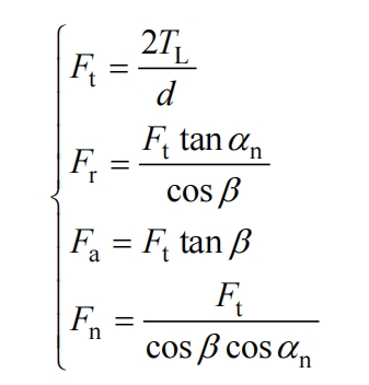
In the formula, Fn, Fr, Ft, and Fa represent the normal meshing force, radial meshing force component, tangential meshing force component, and axial meshing force component of the helical gear, respectively; TL is the load torque applied to the gear; D is the diameter of the gear indexing circle; α N is the normal pressure angle of the gear; β The spiral angle of the dividing circle.
| Meshing force | Theoretical value/N | Simulation value/N | Relative error/% |
| Tangential force | 1389.08 | 1390.54 | 0.11 |
| Radial force | 598.01 | 616.42 | 3 |
| Axial force | 877.46 | 905.22 | 3.1 |
Excluding interference from other factors, only the meshing effect of the gear pair was considered during verification. The simulated meshing force and theoretical calculation values are shown in Table 2. Compared to the theoretical calculation values, the simulated values are larger, mainly because the gear pair model uses a rigid body and considers friction. The maximum deviation between simulated values and theoretical values is 3.1%, which is within a reasonable range, so the setting of gear contact parameters is reasonable.
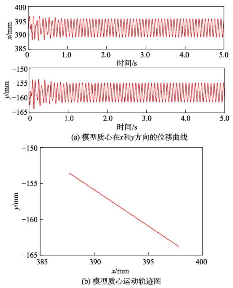
Secondly, the correctness of the virtual prototype model of the shaker system can be verified through the kinematic parameters related to the center of mass of the vibrating screen. As shown in Figure 2 (a), with a running time of 5 seconds, it can be seen that after the system enters a stable working state, the displacement curves of the center of mass of the vibrating screen model in the x and y directions show a simple chord pattern, which is consistent with the motion law of the exciter center of mass derived in reference [15]. The amplitudes in the x and y directions of the vibrating screen are 3.32 mm and 3.34 mm, respectively. After synthesis, it can be concluded that the amplitude of the vibrating screen during operation is 4.7 mm, which is basically consistent with the vibration screen amplitude of 4.8 mm in actual working conditions. In addition, Figure 2 (b) shows the motion trajectory of the exciter’s center of mass. It can be seen that the displacement trajectory of the vibrating screen is approximately a straight line, that is, the screen body undergoes reciprocating linear vibration in the 45 ° direction, which is consistent with the actual working conditions, thus verifying the correctness of the overall model of the excitation system.