
Introduction
The N2 speed indicator of a certain aircraft was zero during flight, resulting in an engine-out stall.
After landing, the aircraft was inspected for its lubricating oil accessories and it was found that
There are many small particles in the oil filter of the oil accessories and metal chip detector.
Metal scraps, confirmed to be copper scraps through energy spectrum analysis
Low alloy steel with carbonitriding layer structure, so it is suspected to have teeth
The wheel is worn. The material designation of the driving gear and the driven gear is
12Cr2Ni4A steel, surface treated with carbonitriding. On-site When disassembling the speed sensor mounting base of oil accessory N2, it was found that the driving gear The driven gear has serious wear and some broken teeth. In order to Determine the failure nature and cause of the N2 sensor drive gear and driven gear Therefore, an analysis and discussion was conducted.
Analysis process
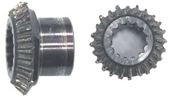
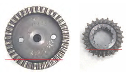
The appearance of the faulty gear is shown in the figure. From the figure,
There are large areas of wear on the teeth of both the drive gear and the driven gear, and the
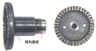
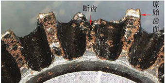
There are visible circumferential wear marks on the side wall of the driving gear. Of the 38 teeth on the driven gear,The tip of the 33 teeth has chipped, and most of the chipped fractures are
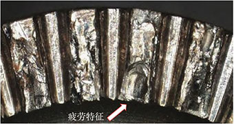
The voltage is relatively high and the wear is severe, and no fatigue characteristics are observed on the remaining original fracture surface.A small part of the block has a flat fracture surface with obvious radiating ribs The line and fatigue arc are shown in the figure. There are 5 teeth without chipping on the tooth top.The tooth wear marks are relatively slight. In addition, at the bottom of the driven gear teeth,
There are contact marks from the engagement of the driven gear and the driving gear. Figure 2
The tooth indicated by the arrow is a fatigue fracture, which extends from the tooth surface near the tooth tip in the counterclockwise direction to the tooth root. The fatigue propagation zone can be seen as a fatigue arc The fatigue propagation area is relatively large, so it is judged that this round of
The head gear is broken, and there are wear marks on the 24 gear teeth on the driving gear.
It is relatively uniform, with a wear depth of about 0.5mm, and there is a gap at the bottom of the tooth.
There are contact and engagement marks. In addition, there are 5 broken tooth roots on the driving gear
The fracture is uneven and severely worn, and the fracture microstructure cannot be observed
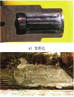
The appearance is shown in the figure. After inspecting the shaft end notch of the driven gear,
It is found that there is axial extrusion wear on the mating surface between the square hole and the pin shaft. The trace is shown in the figure.
SEM analysis
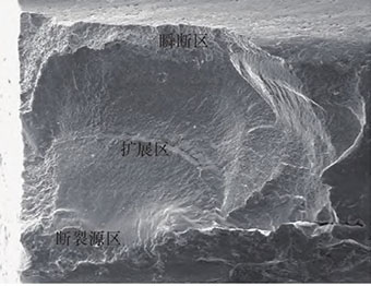
Through comparative observation, the microtopography of the first broken tooth of the driven gear is shown in the figure As shown in the figure, there is a clear fracture source on the fracture surface
zone, expansion zone and transient zone. Converged by radiating and fatigue arcs
Trend judgment: The fracture source area is a short-line source located on the gear surface, short
The line source indicates that the fatigue initiation stress is relatively high, and the microstructure is shown in Figure 6; The fatigue expansion zone is severely worn, and local fatigue arcs and dense wear are visible.The microstructure of the fatigue band is shown in Figure 7; the area ratio of the instantaneous fracture zone is Small, indicating that the fatigue expansion is very sufficient, and the expansion stress is small. This area Located in the permeation layer area, the fracture microstructure is along the crystal fracture, as shown in Figure 8. The wear marks and chipping micro-morphology of the driven gear tooth tip are shown in Figure 9. It is shown that there are meshing marks with the driving gear on the bottom of the tooth, as shown in Figure As shown in the figure, the source area was analyzed by energy spectrum, and the main component was the matrix No abnormal elements were found.
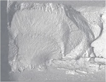
The 1/2 area of the overload broken gear tooth and fracture of the driving gear is severely crushed and worn.The remaining 1/2 area is an overload broken tooth surface, as shown in Figure 12;
The microscopic morphology of the overload fractured tooth surface expansion zone is quasi-cleavage morphology, as shown in Figure shown; the remaining gear teeth have similar shapes of extrusion wear, overload collapse,The driving gear is more seriously damaged than the driven gear, as shown in the figure;The bottom surface of the gear tooth shows a flattened appearance in contact with the top surface of the driven gear tooth.This indicates that the driving gear and the driven gear are not well matched during operation, as shown in the figure as shown.
Metallographic samples were taken from the teeth of the driving gear and the driven gear, as shown in the figure. The samples were ground and polished After corrosion observation, the carbonitriding of the driving gear and driven gear teeth The layer structure and thickness are uniform, and the structure is a small amount of residual austenite + hidden needle Martensite, with tempered martensite in the center, and the organization is in line with the enterprise Relevant standard requirements; the depth of carbonitriding layer of the driven gear is 0.15-0.19mm, meeting the requirements of relevant enterprise standards, active gear tooth tip Severe wear, incomplete carbonitriding layer, unable to judge the original
Whether the thickness of the carbonitriding layer meets the requirements, so it is not evaluated.
As shown in Figure 17-20, the sample of the driven gear and the driving gear are The microhardness (load 2.94N) of the center of the line was measured, and the average microhardness was The degrees are 436HV and 417HV respectively. When the standard requires testing When the test load is 60kg (588N), the hardness is 66-71.5HRA (319-410HV). The analysis suggests that due to gear wear, extrusion
More serious, may lead to slightly higher hardness.
Analyze and discuss
N2 sensor driving gear and driven gear The wheel has no material defects, and the infiltration layer and central structure meet relevant standards.Therefore, it can be determined that the reason for the falling of two gears is related to the material. It has nothing to do with it. The diameter of the driving gear of the N2 sensor is smaller than that of the driven gear, and the teeth The number of wheels is small, so the force frequency and speed are higher than that of the driven gear. The broken tooth of the driving gear is broken from the root, and the fracture is uneven and severely worn The microstructure of the unabraded area is characterized by quasi-cleavage. The driven gear is broken The fracture can be divided into two types: one type of fracture has relatively slight wear, and visible The fatigue source zone, fatigue propagation zone and instantaneous fracture zone, of which the fatigue source zone
Located on the gear surface, it is a linear source; fatigue propagation is sufficient, and visible
fatigue arc and dense fatigue strip; the instantaneous fracture area is relatively small,
The microscopic morphology is characterized by intergranular wear. The other type of wear is more severe, with no visible Microscopic appearance of fracture.
Based on the above test results, it is analyzed that the engine’s N2 The failure of the sensor gear is fatigue. Through review, the assembly process All meet the operating requirements. The surface of the gear shaft and the inner and outer steel sleeves of the bearing There are different degrees of wear on the surface and inside of the tachometer transmission housing These wear marks indirectly indicate that the gears are Abnormality occurs, resulting in abnormal meshing of the tooth surface and contact fatigue stripping.When contact fatigue occurs, the peeling metal particles exacerbate the wear between the teeth, further deteriorating the working environment and increasing the wear of the pitch circle working surface.
As the stress point of the tooth surface, the flaking pit is also the thin area where cracks originate.
Weak links, after crack initiation, are prone to failure under combined stresses (rolling, sliding,
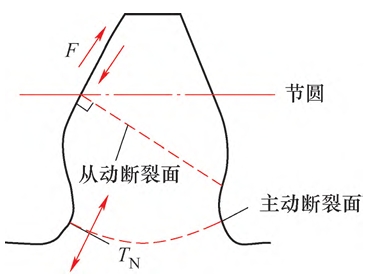
The shear stress and the bending stress and vibration stress along the vertical direction of the working surface The force and fracture of the gear are shown in the figure as it extends to the end.
In addition, due to the load on the gear teeth, the maximum bending stress is
There is a large stress at the root of the tooth and at the transition of the R part.
The force is concentrated, so the root R position becomes the weak point of the gear crack origin
Due to the force applied on the gear during meshing, it is not subject to force during disengagement,
The bending stress on the gear tooth is a pulsating stress; at higher bending stresses
Under repeated action, fatigue cracks occur at the root of the tooth and gradually expand to
The entire gear tooth is broken, and the broken teeth of the faulty driving gear are all of this type
Fracture mode. For the driving gear, the root of the tooth is preferred to the tooth surface
Cracks indicate that the stress concentration level is higher than that of the fatigue flaking pits on the tooth surface. large, otherwise it will preferentially crack from the peeling position on the tooth surface, such as the driven gear Fracture.
Conclusion remarks
1) Submit the materials of the driving gear and driven gear of the N2 sensor for inspection
The heat treatment indicators meet the technical requirements.
2) The reason for the failure of the driving gear and the driven gear is due to the
The fatigue fracture and wear caused by abnormality.