
In the manufacturing of fine-pitch gears, which are critical components in precision devices such as communication systems, service robots, and medical instruments, gear hobbing is a widely used process due to its ability to produce high-strength metal gears suitable for high-torque micro-transmission systems. However, the small size of these gears makes them particularly susceptible to thermal deformation during gear hobbing, leading to issues with dimensional accuracy and surface quality. This study focuses on developing a thermal-mechanical coupling model for intermittent gear hobbing of fine-pitch gears, validated through experiments, to analyze the effects of various parameters on cutting stress, surface temperature, and thermal deformation. The findings aim to optimize the gear hobbing process for improved precision and surface integrity.
The gear hobbing process is based on the generating method, where the relative motion between the hob and the gear blank simulates the meshing of a rack and pinion. This method involves intermittent cutting actions that progressively form the gear teeth. The key motions in gear hobbing include the rotation of the hob, the feed motion, and the rotation of the workpiece, which are controlled by parameters such as hob spindle speed, feed rate, and workpiece speed. For fine-pitch gears, the shallow tooth slots often allow for single-pass hobbing without the need for additional operations. The relationship between the hob and gear blank motions can be described by the following equations:
$$ \phi = \frac{\theta}{z} $$
$$ l = \frac{v \theta}{2\pi} $$
where $\phi$ is the workpiece rotation angle, $\theta$ is the hob rotation angle, $z$ is the number of teeth on the gear, $l$ is the feed distance, and $v$ is the feed amount. To simulate the intermittent nature of gear hobbing, a simplified model with a single cutting tooth undergoing cyclic cutting and retraction motions is used. The motion parameters include the cutting angular velocity $\omega_{cut}$, retraction angular velocity $\omega_{re}$, adjustment velocity $v_{ad}$, and workpiece adjustment angular velocity $\omega_{ad}$, defined as:
$$ \omega_{cut} = \frac{2\pi n}{60} $$
$$ \omega_{re} = \frac{\phi_{cut}}{t_{re}} $$
$$ v_{ad} = \frac{p}{z_{hob}} \div \left( \frac{2\pi}{z_{hob} \omega_{cut}} – \frac{\phi_{cut}}{\omega_{cut}} – t_{re} \right) $$
$$ \omega_{ad} = \frac{2\pi}{z_{hob} z} \div \left( \frac{2\pi}{z_{hob} \omega_{cut}} – \frac{\phi_{cut}}{\omega_{cut}} – t_{re} \right) $$
Here, $n$ is the hob spindle speed, $\phi_{cut}$ is the single cutting rotation angle, $t_{re}$ is the retraction time, $p$ is the circular pitch, and $z_{hob}$ is the number of hob teeth. This model efficiently captures the discontinuous cutting behavior in gear hobbing machine operations.
The material removal during gear hobbing involves high strain rates and temperatures, necessitating a robust material model. The Johnson-Cook (J-C) model is employed to describe the plastic flow and fracture behavior of the gear blank material (45# steel) under dynamic loading conditions. The J-C constitutive model accounts for strain hardening, strain rate sensitivity, and thermal softening, expressed as:
$$ \sigma_y = \left( A + B \varepsilon_p^n \right) \left(1 + C \ln \dot{\varepsilon}^* \right) \left(1 – T^{*m} \right) $$
where $\sigma_y$ is the equivalent yield stress, $A$ is the initial yield strength, $B$ is the strain hardening coefficient, $\varepsilon_p$ is the equivalent plastic strain, $n$ is the strain hardening exponent, $C$ is the strain rate sensitivity coefficient, $\dot{\varepsilon}^* = \dot{\varepsilon} / \dot{\varepsilon}_0$ is the dimensionless plastic strain rate (with $\dot{\varepsilon}_0 = 1.0 \, \text{s}^{-1}$ as the reference strain rate), and $T^* = (T – T_r) / (T_m – T_r)$ is the homologous temperature (with $T$, $T_r$, and $T_m$ representing the current, room, and melting temperatures, respectively). The J-C failure model predicts material damage and is given by:
$$ \varepsilon_f = \left[ D_1 + D_2 \exp(D_3 \sigma^*) \right] \left(1 + D_4 \ln \dot{\varepsilon}^* \right) \left(1 + D_5 T^* \right) $$
where $\varepsilon_f$ is the failure strain, $D_1$ to $D_5$ are failure parameters, and $\sigma^*$ is the stress triaxiality. Material failure occurs when the damage parameter $D$ accumulates to 1, calculated as:
$$ D = \sum \frac{\Delta \varepsilon_{eq}}{\varepsilon_f} $$
with $\Delta \varepsilon_{eq}$ being the equivalent plastic strain increment. This approach allows for accurate simulation of chip formation and material removal in gear hobbing.
For the thermal-mechanical coupling analysis, a finite element model of the gear hobbing process is developed. The hob is treated as a rigid body, and face-to-face contact with the gear blank accounts for friction and heat generation. The boundary conditions are set based on the motion equations, with hob speeds ranging from 1000 to 1500 rpm. The gear blank material is 45# steel, and its properties and J-C parameters are summarized in the following table:
| Parameter | Value |
|---|---|
| Density (g/cm³) | 7.9 |
| Elastic Modulus (GPa) | 210 |
| Poisson’s Ratio | 0.275 |
| Thermal Expansion Coefficient (°C⁻¹) | 1.16×10⁻⁵ |
| Thermal Conductivity (W/m·K) | 52.34–31.18 (0–1060°C) |
| Specific Heat Capacity (J/kg·K) | 476–690 (28–1060°C) |
| Inelastic Heat Fraction | 0.9 |
| Yield Strength A (MPa) | 507 |
| Strain Hardening Coefficient B (MPa) | 320 |
| Strain Rate Sensitivity Coefficient C | 0.28 |
| Strain Hardening Exponent n | 0.064 |
| Thermal Softening Exponent m | 1.06 |
| Failure Parameter D₁ | 0.15 |
| Failure Parameter D₂ | 0.72 |
| Failure Parameter D₃ | 1.66 |
| Failure Parameter D₄ | 0.005 |
| Failure Parameter D₅ | -0.84 |
| Melting Temperature T_m (°C) | 1492 |
The heat generation during gear hobbing arises from plastic deformation and friction. The heat flux due to plastic deformation is given by:
$$ Q_{pl} = \frac{1}{2\Delta t} \eta \dot{\varepsilon}^* \mathbf{n} : (\sigma + \sigma_t) $$
where $\Delta t$ is the time increment, $\eta$ is the inelastic heat fraction, $\mathbf{n}$ is the direction vector of plastic flow, and $\sigma$ and $\sigma_t$ are the stress tensors at times $t+\Delta t$ and $t$, respectively. The frictional heat flux is calculated as:
$$ q_{fri} = \eta_f \tau \frac{\Delta s}{\Delta t} $$
with $\eta_f$ being the friction heat conversion coefficient, $\tau$ the friction stress, and $\Delta s$ the slip increment. Heat conduction within the gear blank follows Fourier’s law:
$$ q_c = -\lambda \nabla T $$
where $\lambda$ is the thermal conductivity and $\nabla T$ is the temperature gradient. Heat dissipation to the environment is modeled as:
$$ q_h = h (T – T_r) $$
with $h$ as the convective heat transfer coefficient. These equations enable the simulation of temperature distribution and thermal deformation during gear hobbing.
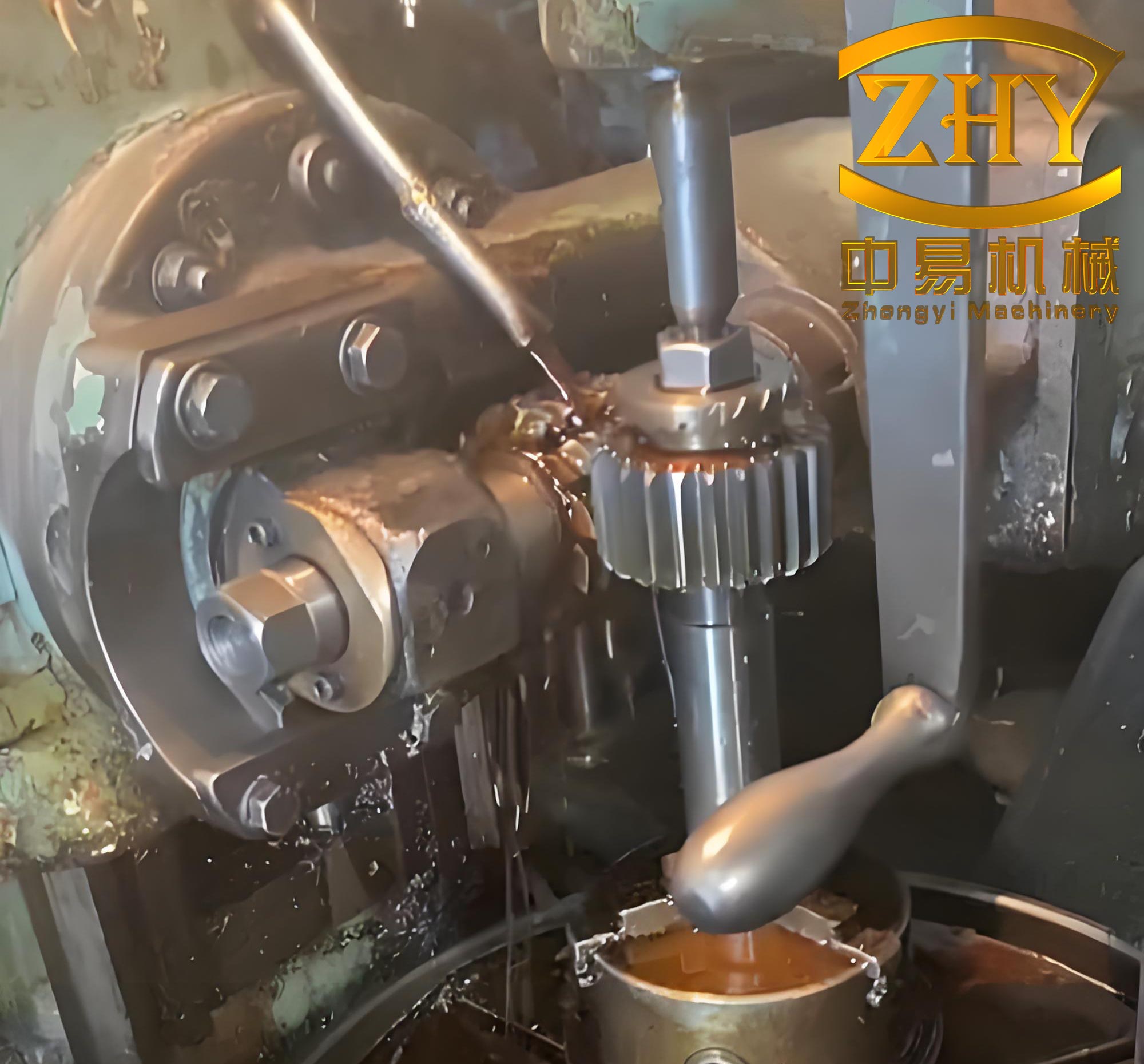
To validate the model, experimental studies are conducted on fine-pitch gears made of 45# steel, with a module of 0.6 mm, 37 teeth, a face width of 5 mm, and a bore diameter of 4 mm. The gears are manufactured using a precision gear hobbing machine with a feed rate of 0.3 mm/rev and hob speeds of 1000, 1200, 1300, 1400, and 1500 rpm. For each speed, three replicate specimens are produced. The gear hobbing machine setup is crucial for achieving accurate results, and the following image illustrates a typical gear hobbing machine used in such processes:
Surface defects and roughness are analyzed using deep-depth microscopy. The roughness parameter $R_a$ (arithmetic average deviation) is calculated over five sampling lengths along the tooth height, based on least-squares fitting to the profile. Results show that roughness is higher near the tooth tip and lower in the middle and root regions, due to the denser cutting actions during form generation. Additionally, the common normal deviation $E_W$ is measured to assess thermal deformation. The theoretical common normal length $W$ is given by:
$$ W = \left[ (k – 0.5)\pi + z \cdot \text{inv} \alpha \right] m \cdot \cos \alpha $$
$$ k = \frac{\alpha z}{180} + 0.5 $$
where $k$ is the number of spanned teeth (rounded), $m$ is the module, and $\text{inv} \alpha = \tan \alpha – \alpha$ is the involute function of the pressure angle $\alpha$. For the specimen gears, $W = 8.282$ mm. The measured deviations are compared with simulated equivalent plastic strain (PEEQ) values, showing a correlation where both increase with hob speed, thus validating the model.
The influence of gear module on gear hobbing characteristics is investigated by simulating modules of 0.4, 0.6, 0.8, and 1.0 mm, with a constant cutting speed of 1.4426 m/s at the pitch circle. The following table summarizes the results for cutting stress, surface temperature, and equivalent plastic strain:
| Module (mm) | Peak Cutting Stress (MPa) | Surface Temperature (°C) | Equivalent Plastic Strain |
|---|---|---|---|
| 0.4 | 2511.24 | 45.2 | 0.28 |
| 0.6 | 1987.35 | 48.7 | 0.32 |
| 0.8 | 1720.18 | 52.1 | 0.35 |
| 1.0 | 1578.78 | 49.5 | 0.31 |
As the module increases from 0.4 to 1.0 mm, the peak cutting stress decreases by approximately 37%, due to larger tool dimensions and load-bearing areas. Surface temperature and plastic strain initially rise with module up to 0.8 mm, owing to higher material removal rates, but decrease at 1.0 mm because of the larger hob diameter and reduced speed, which prolongs intermittent cutting intervals. The strain-to-thickness ratio decreases with module, amplifying errors in fine-pitch gears and making high-precision manufacturing more challenging.
The effect of cutting speed is studied by varying it from 0.6 to 3.0 m/s for a module of 0.6 mm. The results are presented in the table below:
| Cutting Speed (m/s) | Peak Cutting Stress (MPa) | Surface Temperature (°C) | Equivalent Plastic Strain |
|---|---|---|---|
| 0.6 | 1850.50 | 35.2 | 0.18 |
| 1.2 | 1920.75 | 42.8 | 0.25 |
| 1.8 | 1987.35 | 48.7 | 0.32 |
| 2.4 | 2050.20 | 53.1 | 0.38 |
| 3.0 | 2090.60 | 55.8 | 0.45 |
Increasing the cutting speed from 0.6 to 3.0 m/s raises the peak cutting stress by 13%, surface temperature by 77%, and equivalent plastic strain by 150%. This is attributed to higher material removal rates and intensified heat generation, leading to greater thermal distortion. Beyond 2.4 m/s, the temperature and strain growth rate slows as chips carry away heat more efficiently. Thus, reducing hob speed or diameter can mitigate thermal effects and improve accuracy in gear hobbing machine operations.
Heat transfer conditions are evaluated by applying convective heat transfer coefficients of 0, 1000, and 15,000 W/(m²·K), representing dry cutting, natural convection with cutting fluid, and forced convection, respectively. The analysis focuses on tooth tip nodes due to strain concentration. The outcomes are as follows:
| Convective Heat Transfer Coefficient (W/(m²·K)) | Tooth Tip Temperature (°C) | Tooth Tip Equivalent Plastic Strain |
|---|---|---|
| 0 | 46.5 | 0.36 |
| 1000 | 38.2 | 0.34 |
| 15000 | 31.5 | 0.32 |
Enhancing convective cooling reduces the tooth tip temperature from 46.5°C to 31.5°C and the plastic strain from 0.36 to 0.32, demonstrating that forced convection with cutting fluid effectively minimizes heat accumulation and thermal deformation. This highlights the importance of cooling strategies in gear hobbing for extending tool life and ensuring gear quality.
In conclusion, this study establishes a thermal-mechanical coupling model for intermittent gear hobbing of fine-pitch gears, validated through experiments. The model accurately predicts cutting stress, temperature, and deformation, revealing that module size significantly influences stress levels, while cutting speed and heat transfer conditions dominate thermal effects. Fine-pitch gears are more prone to accuracy issues due to their smaller dimensions amplifying errors. To achieve high precision and surface quality in gear hobbing, it is recommended to optimize parameters such as reducing hob speed or diameter to lower cutting speeds and implementing forced convection cooling. These strategies can effectively control thermal deformation and enhance the performance of gear hobbing machine processes in manufacturing fine-pitch gears.