
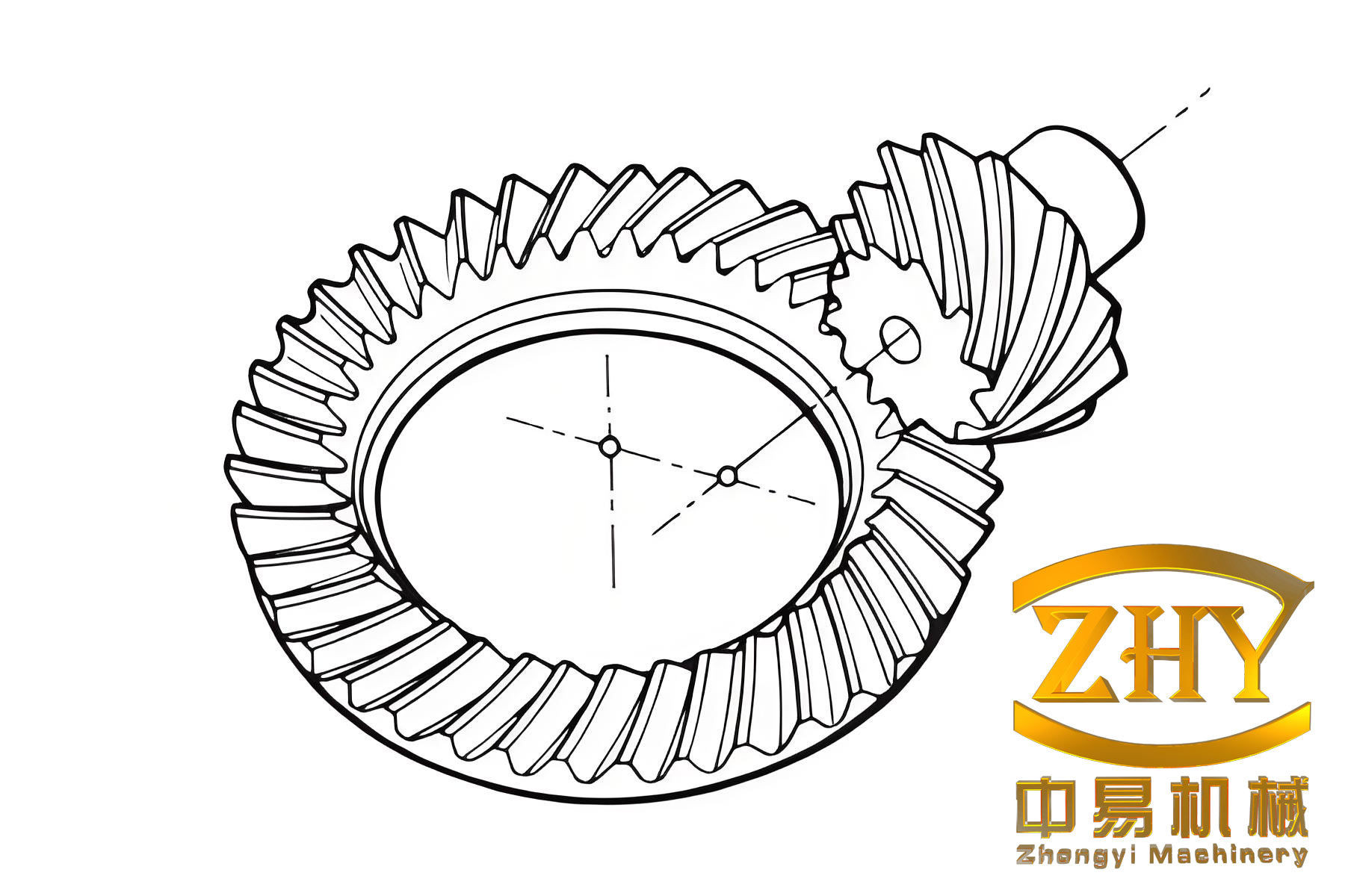
The pursuit of high reduction ratios in power transmission systems has long been dominated by worm drives and planetary gear sets. However, these solutions often come with significant drawbacks, including complex manufacturing processes, high costs, and challenges in maintaining precision. In contrast, the hypoid bevel gear offers a compelling alternative. High-Reduction Hypoid (HRH) gears can be manufactured using the same machine tools, cutters, and grinding processes as conventional spiral bevel gears. Both the pinion and gear can be case-hardened to create durable hard-faced teeth, significantly enhancing their longevity and load capacity. Furthermore, the inherent offset in hypoid bevel gear design promotes excellent lubrication, and even at extreme reduction ratios exceeding 60:1, transmission efficiency can remain above 80%. Despite these advantages, the design and performance control of HRH gears present formidable challenges due to the complex spatial meshing theory and the intricate topological structure of their tooth surfaces, making both machining design and numerical simulation particularly difficult.
This article addresses specific problems encountered in HRH gear design: insufficient curvature on the gear tooth profile and the highly twisted tooth surface of the pinion resulting from its large spiral angle. To overcome these issues, a novel methodology is proposed. The gear is modified using a tool profile correction to achieve localized point contact, while the pinion is generated using a simplified, standard hobbing method, thereby reducing the complexity of its machine setup parameters. This approach aims to simplify manufacturing while ensuring superior meshing performance. The core of the analysis revolves around the construction and examination of the Ease-off topology, a powerful tool for visualizing and optimizing tooth surface modifications.
The fundamental mathematical model begins with the modification of the gear cutter. The cutter profile is modified along its width direction ‘w’ using a second-order parabolic function. The cutter surface is defined in its coordinate system \( S_c(x_c, y_c, z_c) \). The parabolic modification and its derivative are given by:
$$
w = \frac{1}{2}a_1 (u – u_0)^2, \quad w’ = a_1 (u – u_0)
$$
where \( a_1 \) is the curvature correction parameter and \( u_0 \) is the datum point parameter. The effective pressure angle \( \alpha(u) \) then becomes a function of the parameter \( u \):
$$
\alpha(u) = \alpha_0 + \arctan(w’)
$$
The equation for the modified cutter surface and its unit normal vector can be expressed as:
$$
\mathbf{r_c} = \begin{bmatrix} r_u \cos \theta \\ r_u \sin \theta \\ u \cos \alpha(u) \end{bmatrix}, \quad \mathbf{n_c} = \begin{bmatrix} -\cos \alpha(u) \cos \theta \\ \cos \alpha(u) \sin \theta \\ \sin \alpha(u) \end{bmatrix}
$$
where \( r_u = r_0 – u \sin \alpha(u) \). For formate-cut gears, the gear tooth surface is directly derived from this cutter surface via coordinate transformation.
The meshing relationship between the gear and the conjugate pinion is established using a set of spatial coordinate systems. The gear and pinion rotate about their own axes, and the meshing condition must be satisfied. If the gear tooth surface is known as \( \mathbf{r_2} \) with normal \( \mathbf{n_2} \) in its coordinate system \( S_2 \), it can be represented in the fixed meshing coordinate system \( S_m \) as:
$$
\mathbf{r_{m2}} = \mathbf{M_{m2}} \mathbf{r_2}, \quad \mathbf{n_{m2}} = \mathbf{L_{m2}} \mathbf{n_2}
$$
The conjugate pinion surface is then obtained through the meshing equation and inverse transformation:
$$
f(u, \theta, \phi) = 0, \quad \mathbf{r_1} = \mathbf{M_{1m}} \mathbf{r_{m2}}, \quad \mathbf{n_1} = \mathbf{L_{1m}} \mathbf{n_{m2}}
$$
where \( \phi \) is the motion parameter. The pinion surface generated from the unmodified, fully conjugate gear serves as the reference or “standard” pinion.
The transition from line contact to controlled point contact is achieved by introducing a mismatch between the gear and pinion tooth surfaces. The modification on the gear primarily compensates for the lack of profile curvature. The longitudinal mismatch is inherently created by using different cutter radii for the gear and pinion. The resulting deviation, known as the Ease-off or mismatch, is defined as the normal distance between the real pinion surface and the conjugate pinion surface that would perfectly match the modified gear. This Ease-off value, plotted over the tooth surface, forms a three-dimensional topographical map called the Ease-off surface. This surface is crucial for predicting and controlling contact patterns, transmission error, and sensitivity to misalignment.
While gear tool modification can initiate point contact, fine-tuning the contact path and other performance parameters requires optimization of the pinion’s machine settings. An iterative process is employed: the pinion machine settings are initially calculated using a synthesis method; a 3D tooth model is created from these settings; the Ease-off surface is constructed and analyzed to extract performance parameters like contact path, principal curvatures, and transmission error; the settings are then adjusted until the desired contact performance is achieved.
To demonstrate this process, a specific HRH gear pair with a 3:60 ratio (3 teeth on the pinion, 60 teeth on the gear) is analyzed. The primary geometric parameters and the final optimized machine settings are summarized in the tables below.
| Parameter | Pinion | Gear |
|---|---|---|
| Number of Teeth | 3 | 60 |
| Face Width (mm) | 28.979 | 20 |
| Mean Spiral Angle (°) | 72 | 32.8983 |
| Pitch Angle (°) | 10.9919 | 75.8605 |
| Outer Diameter (mm) | 27.9074 | 145 |
| Offset (mm) | 40 | — |
| Machine Setting | Pinion (Concave) | Gear (Convex) |
|---|---|---|
| Profile Curvature Parameter \( a_1 \) | — | 0.014 |
| Cutter Radius \( r_c \) (mm) | 37.6 | 37.4 |
| Pressure Angle \( \alpha_0 \) (°) | 20.5 | 19.0 |
| Radial Setting \( S_r \) (mm) | 51.9712 | 53.1513 |
| Machine Roll Ratio \( i_m \) | 19.9492 | — |
The resulting Ease-off topographical map for the pinion concave side reveals a characteristic “saddle” shape. The modification is zero at a specific datum point and increases towards the edges. The mismatch values at the entry and exit regions are approximately 26 μm and 35 μm, respectively. Lines of constant Ease-off value, known as contact-off lines, represent instantaneous contact ellipses under load. The trajectory of the minimum point on these lines defines the contact path across the tooth flank. The projection of the Ease-off values along this path directly yields the transmission error (TE) curve, a critical indicator of meshing smoothness and dynamic excitation. For this optimized hypoid bevel gear pair, the TE curve shows a peak-to-peak value of approximately -1.0 μm. Furthermore, the analysis of multiple meshing positions indicates that the TE curves overlap between the first and sixth meshing cycles, confirming a contact ratio greater than 5. This high contact ratio is essential for the smooth and quiet operation of the low-tooth-count hypoid bevel gear.
To visually verify the contact performance, three-dimensional models of the gear pair are created. Numerical coordinates of the tooth flanks are calculated based on the mathematical models and imported into CAD software to build solid models. A comparison between the standard (unmodified conjugate) pinion and the Ease-off modified pinion shows a clear difference: the modified pinion has a narrower tip and increased profile curvature, which helps avoid edge contact at the tip and root. These models are then assembled in a motion simulation environment with a prescribed small separation (simulating the thickness of marking compound) to perform a virtual rolling test.
The motion simulation provides a clear, dynamic view of the contact pattern. For the unmodified conjugate pair, the contact appears as a broad band, indicating line contact, with severe edge contact at the tip and root—a highly undesirable condition. In contrast, the simulation for the Ease-off modified hypoid bevel gear pair shows a distinct, elliptical contact patch located in the central region of the tooth,偏向 the toe (small end). Critically, edge contact is completely eliminated. The simulation also visually confirms that up to five tooth pairs are in contact simultaneously at certain positions, validating the high contact ratio predicted by the transmission error analysis. This simulated contact pattern aligns perfectly with the goals of the Ease-off modification.
The theoretical design and simulation were validated through physical testing. First, a rolling test was conducted on a gear rolling tester. The gear set, manufactured according to the designed parameters, was assembled at the specified mounting distances. A marking compound was applied to the teeth, and the gears were run under light load. The resulting contact pattern on the gear convex side showed an elliptical shape located in the mid-toe region, with no edge contact. The size and location were satisfactory and closely matched the contact area observed in the 3D motion simulation, confirming the accuracy of the modification methodology and the仿真 results.
To evaluate the dynamic performance, a comprehensive test rig was established. It consisted of a drive motor, torque sensors on both the input and output shafts, the HRH gearbox prototype, and a magnetic powder brake for loading. A multi-channel data acquisition system was used to measure vibration acceleration in three orthogonal directions: vertical (x), axial (z), and horizontal (y). Tests were conducted under various operating conditions: three input speeds (710, 1410, 2100 rpm) and two load levels (50 N·m and 200 N·m on the gear shaft).
The vibration spectra were analyzed, focusing on the first ten harmonics of the gear mesh frequency. Under a constant speed of 1410 rpm, the vibration characteristics at 50 N·m and 200 N·m loads were compared. The spectra showed distinct peaks at the mesh frequency and its harmonics, with the second harmonic being the most prominent. Interestingly, the vibration amplitude at the 200 N·m load was generally lower than that at the 50 N·m load across all three measurement directions. This phenomenon can be attributed to the increased mesh stiffness and effective contact ratio under higher load, which reduces dynamic transmission error and excitation. A comparison across different speeds under constant load revealed that vibration amplitudes increased significantly with speed. The strongest vibration energy was concentrated in the 100-200 Hz band, which corresponded to the mesh frequency range for the tested speeds, indicating a region of sensitivity. A summary of the vertical vibration acceleration at the dominant 2nd mesh harmonic under all test conditions is presented below.
| Load (N·m) | Speed (rpm) | Mesh Freq. (Hz) | Vertical Vib. Accel. at 2xMF (m/s²) |
|---|---|---|---|
| 50 | 710 | 35.5 | 0.102 |
| 1410 | 70.5 | 0.443 | |
| 2100 | 105 | 0.895 | |
| 200 | 710 | 35.5 | 0.038 |
| 1410 | 70.5 | 0.159 | |
| 2100 | 105 | 0.521 |
In conclusion, this study successfully addressed key design challenges for High-Reduction hypoid bevel gears. The proposed method of gear tool modification combined with pinion machine setting optimization effectively transformed the tooth contact from a sensitive line contact to a robust, localized point contact. The Ease-off topology served as an essential tool for visualizing the modification and predicting meshing performance. Three-dimensional motion simulation provided an intuitive and effective means to visualize the contact pattern and contact ratio, results which were consistent with theoretical predictions. Finally, physical experiments, including rolling tests and dynamic vibration analysis, validated the design. The gear pair exhibited excellent contact patterns free from edge contact, stable meshing with a high contact ratio, and favorable dynamic behavior where increased load slightly dampened vibration. This comprehensive approach, from mathematical modeling and Ease-off analysis to 3D simulation and experimental testing, demonstrates a viable and effective framework for designing and developing high-performance, high-reduction ratio hypoid bevel gear drives.