
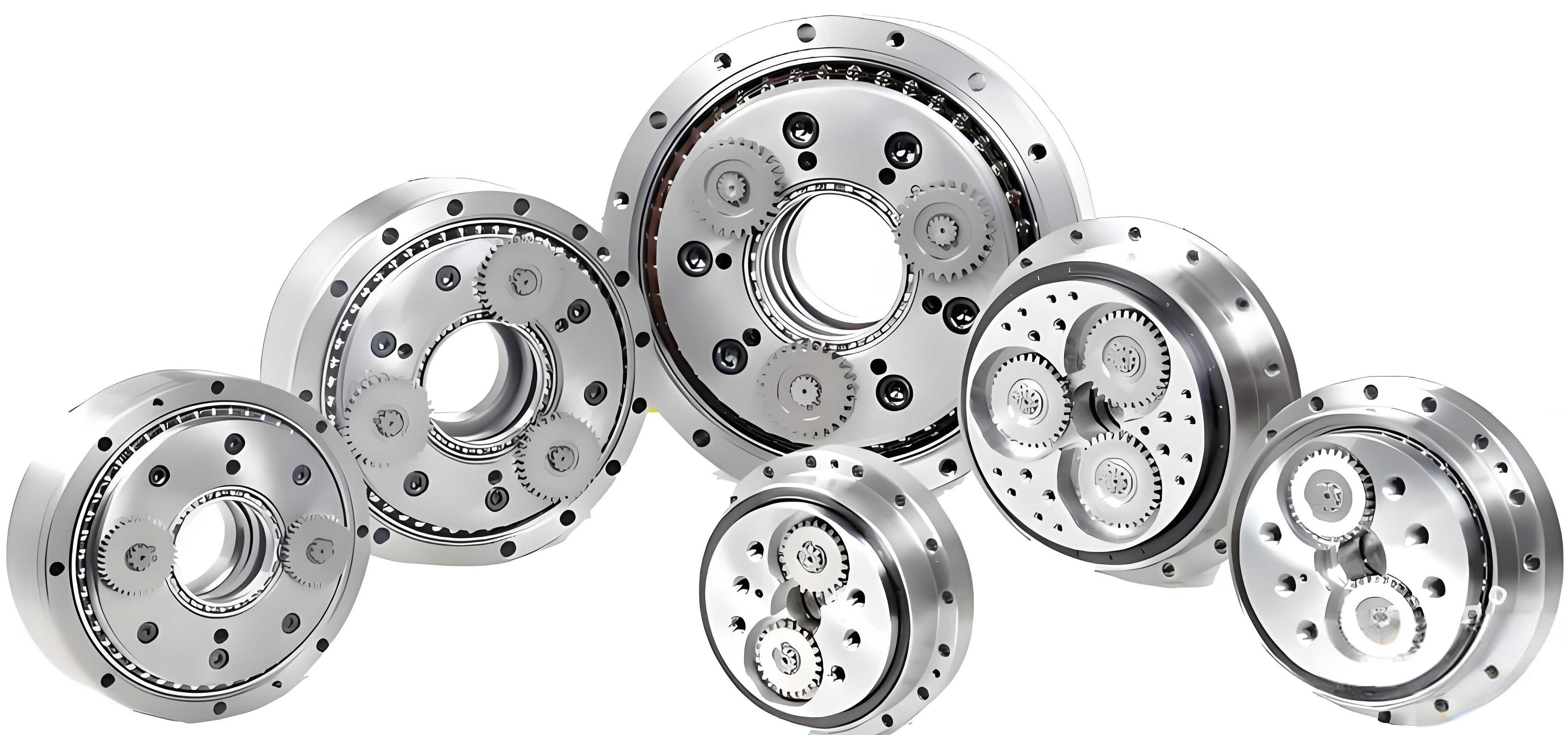
The rotary vector reducer, commonly known as the RV reducer, is a precision transmission device renowned for its high torsional stiffness, compact structure, and excellent positioning accuracy. These attributes make it indispensable in advanced robotics, precision machine tools, and aerospace mechanisms. At the heart of a rotary vector reducer lies its unique two-stage transmission system. The first stage is typically a standard involute planetary gear train, which provides an initial speed reduction. The second stage, which is the critical differentiating component, is the cycloid pinwheel transmission. This stage is responsible for the high reduction ratio and the exceptional load distribution capabilities of the rotary vector reducer.
The cycloid pinwheel mechanism operates on a principle where a cycloidal disk, mounted on an eccentric crankshaft, meshes with a set of stationary pinwheels housed in the reducer’s casing. The motion results in a compound rotation and revolution of the cycloid disk, delivering smooth, high-ratio speed reduction to the output flange. Unlike gear meshing with theoretical line contact, the interaction between the cycloid disk tooth flank and the cylindrical pin is a complex, transient contact process. The lubrication conditions at this interface are paramount, directly governing the transmission efficiency, contact fatigue life, wear resistance, and ultimately, the reliability and longevity of the entire rotary vector reducer.
While often lubricated with grease for life, the elastohydrodynamic lubrication (EHL) and mixed lubrication phenomena within the cycloid pinwheel pair are complex and have not been as extensively studied as those in conventional gear pairs. The contact geometry, load, and entraining velocity vary significantly at different points along the tooth profile during meshing. Furthermore, practical manufacturing considerations necessitate profile modifications (such as equidistant, moving, and tooth height modifications) and topological modifications (like crowning and end-relief) to the cycloid teeth. These modifications transform the theoretical line contact into a finite line or elliptical point contact, critically altering the pressure distribution and film formation. Analyzing the lubrication characteristics, therefore, requires a transient, point-contact EHL approach that accounts for real surface roughness, leading to a mixed lubrication regime where load is shared between the fluid film and contacting asperities.
This article presents a comprehensive analysis of the lubrication characteristics in the cycloid pinwheel transmission of a rotary vector reducer. By discretizing the tooth profile and analyzing key contact points throughout the meshing cycle, we investigate the influence of critical design and operational parameters. Utilizing advanced numerical techniques like the Progressive Mesh Densification method, we solve for the transient film thickness and pressure under both smooth and rough surface conditions. The goal is to identify regions of poor lubrication, understand the mixed lubrication behavior, and provide foundational insights that can guide optimal tooth profile modification strategies for enhancing the performance of rotary vector reducers.
Mathematical Foundation and Key Contact Parameters
The analysis begins with the mathematical description of the modified cycloid tooth profile. The modification is essential in practical rotary vector reducers to compensate for machining errors, ensure proper assembly clearance, and create space for lubrication.
The coordinates of a point on the modified cycloid profile can be expressed as:
$$
\begin{aligned}
x &= R_p^* \cos(\theta) – e^* \cos(Z_p \theta / Z_c) – R_{rp}^* S^* \cos(\theta – \xi) \\
y &= R_p^* \sin(\theta) – e^* \sin(Z_p \theta / Z_c) + R_{rp}^* S^* \sin(\theta – \xi)
\end{aligned}
$$
where:
$$
\xi = \arctan\left(\frac{K_1^* \sin\theta}{1 – K_1^* \cos\theta}\right), \quad S^* = \sqrt{1 + (K_1^*)^2 – 2K_1^* \cos\theta}
$$
The modified parameters are: $R_p^* = R_p + \Delta R_p$ (radius of pin circle), $R_{rp}^* = R_{rp} + \Delta R_{rp}$ (pin radius), $e^* = e + \Delta e$ (eccentricity), and $K_1^* = Z_p e^* / R_p^*$ (modified shortcut coefficient). $Z_c$ and $Z_p$ are the numbers of cycloid and pin teeth, respectively, with typically $Z_p = Z_c + 1$.
The instantaneous equivalent radius of curvature $R$ at the contact point, a critical parameter for EHL analysis, is derived as:
$$
\frac{1}{R} = \frac{1}{R_c} + \frac{1}{R_{rp}^*} \approx \frac{1}{R_{rp}^*} \left[ 1 + \frac{Z_p(1+K_1^{*2} – 2K_1^*\cos\theta)^{3/2}}{Z_c(1+K_1^{*2}) – K_1^*(Z_c+Z_p)\cos\theta} \right]
$$
Here, $R_c$ is the radius of curvature of the cycloid tooth at the meshing point. For the high-load capacity of a rotary vector reducer, this radius significantly influences the contact pressure and film thickness.
Entraining Velocity
Assuming near-pure rolling conditions (a valid approximation for well-modified profiles with minimal slide-to-roll ratio), the entraining velocity $U$ is the average of the surface velocities of the two bodies in the tangential direction. For the cycloid pinwheel transmission in a rotary vector reducer with a fixed pinwheel housing, the entraining velocity at a meshing point defined by angle $\theta$ is given by:
$$
U(\theta) = \frac{\pi N_{in}}{60} \cdot \frac{Z_p}{Z_c} \cdot \frac{R_{rp}^* S^* – \sqrt{x_K^2 + y_K^2}}{R_{rp}^* S^*}
$$
where $N_{in}$ is the input speed (crankshaft speed) in rpm, and $(x_K, y_K)$ are the coordinates of the meshing point on the cycloid profile. This velocity is a key driver for hydrodynamic film generation.
Contact Load Distribution
The load distribution among the simultaneously engaged pin teeth is derived from static equilibrium and deformation compatibility. The force on the $i$-th pin tooth is proportional to the moment arm from the cycloid gear’s center. For a rotary vector reducer output torque $T_{out}$, the contact force per unit length $F_i$ (assuming an initial line contact before crowning) is:
$$
F_i(\theta_i) = \frac{4 T_{out} \sin\theta_i}{K_1 Z_c R_p^* B S^*}
$$
where $B$ is the face width of the cycloid gear, and $\theta_i$ is the angular position of the $i$-th pin relative to the line of centers. The load is highest near the center of the meshing arc and decreases towards the ends. The following table summarizes typical material and lubricant properties used in the analysis of a rotary vector reducer.
| Parameter | Value | Unit |
|---|---|---|
| Young’s Modulus (Steel) | 206 | GPa |
| Poisson’s Ratio | 0.3 | – |
| Density (Steel) | 7.85 | g/cm³ |
| Grease Base Oil Viscosity ($\eta_0$) | 0.08 | Pa·s |
| Pressure-Viscosity Coefficient ($\alpha$) | 2.91e-8 | Pa⁻¹ |
| Density (Grease, $\rho_0$) | 0.88 | g/cm³ |
Numerical Analysis of Elastohydrodynamic Lubrication
The lubrication state is governed by the transient Reynolds equation, film thickness equation, load balance equation, and the rheological models for the grease (viscosity-pressure and density-pressure relations). For a point contact with surface roughness, the system is:
Reynolds Equation:
$$
\frac{\partial}{\partial x}\left( \frac{\rho h^3}{12 \eta} \frac{\partial p}{\partial x} \right) + \frac{\partial}{\partial y}\left( \frac{\rho h^3}{12 \eta} \frac{\partial p}{\partial y} \right) = U \frac{\partial (\rho h)}{\partial x} + \frac{\partial (\rho h)}{\partial t}
$$
Film Thickness Equation:
$$
h(x,y,t) = h_0(t) + \frac{x^2}{2R_x(t)} + \frac{y^2}{2R_y(t)} + \delta(x,y,t) + \nu(x,y,t)
$$
where $\delta$ is the combined surface roughness and $\nu$ is the elastic deformation calculated by the Boussinesq integral.
Roelands Viscosity-Pressure Model:
$$
\eta(p) = \eta_0 \exp\left\{ (\ln \eta_0 + 9.67) \left[ -1 + (1 + 5.1 \times 10^{-9} p)^Z \right] \right\}
$$
Density-Pressure Model:
$$
\rho(p) = \rho_0 \left( 1 + \frac{0.6 \times 10^{-9} p}{1 + 1.7 \times 10^{-9} p} \right)
$$
This system is solved numerically using the Progressive Mesh Densification (PMD) method, which starts with a coarse mesh and progressively refines it to achieve accurate and efficient solutions for the mixed EHL problem, crucial for modeling the contacts in a rotary vector reducer.
Influence of Design Parameters
The performance of the rotary vector reducer is sensitive to its design parameters. We analyze their effect on smooth-surface EHL first.
1. Equivalent Radius of Curvature ($R$): As $R$ increases, the contact ellipse becomes longer and narrower. The central film thickness decreases slightly, but the more pronounced effect is on the pressure distribution. The secondary pressure peak at the outlet becomes sharper and shifts inward. The minimum film thickness, often located at the side lobes of the horseshoe-shaped constriction, is more susceptible to reduction with increasing $R$. This is critical for the rotary vector reducer as the radius of curvature varies significantly along the cycloid tooth profile.
2. End and Crowning Modifications: Unmodified edges of finite line contacts suffer severe pressure spikes. Simple end-rounding slightly alleviates this but does not eliminate the spike. Crowning (an arc modification along the tooth face width, with radius $R_y$) is highly effective. It transforms the contact to a nominal point contact, eliminating edge stresses and promoting a more central, elliptical pressure distribution. As the crown radius $R_y$ increases, the contact ellipse lengthens, the maximum pressure decreases, and the film thickness increases. Therefore, optimal crowning is a vital design aspect for the cycloid gear in a rotary vector reducer to prevent edge failures and improve lubrication.
Influence of Process Parameters
1. Load ($F$): Increasing the load in a rotary vector reducer leads to a significant reduction in film thickness according to the EHL scaling laws ($h \propto F^{-0.13}$ for point contact). The pressure increases sub-linearly, and the horseshoe-shaped film constriction becomes wider.
2. Entraining Velocity ($U$): Velocity is the most favorable parameter for film formation ($h \propto U^{0.68}$). Higher input speeds to the rotary vector reducer result in a thicker, more robust lubricant film and a narrower constriction at the outlet.
Dynamic Lubrication Analysis Across the Meshing Cycle
The meshing process in a rotary vector reducer is dynamic. Key parameters—load $F(\theta)$, equivalent radius $R(\theta)$, and entraining velocity $U(\theta)$—vary simultaneously as a function of the meshing phase angle $\theta$. To analyze this, the main working section of the cycloid tooth (typically $\theta \in [30^\circ, 120^\circ]$) is discretized into 15 points. The parameters for a sample RV reducer under a 230 Nm load are tabulated below.
| Point | $\theta$ (deg) | Load $F$ (N/mm) | Radius $R$ (mm) | Velocity $U$ (mm/s) |
|---|---|---|---|---|
| P1 | 27 | 16.70 | 5.23 | 727 |
| P2 | 34 | 24.03 | 3.36 | 702 |
| P3 | 41 | 32.41 | 2.35 | 694 |
| P4 | 48 | 41.51 | 1.80 | 698 |
| P5 | 55 | 50.99 | 1.49 | 711 |
| P6 | 62 | 60.47 | 1.33 | 730 |
| P7 | 69 | 69.54 | 1.24 | 753 |
| P8 | 76 | 77.83 | 1.19 | 778 |
| P9 | 83 | 84.97 | 1.17 | 804 |
| P10 | 90 | 90.61 | 1.17 | 831 |
| P11 | 97 | 94.47 | 1.17 | 857 |
| P12 | 104 | 96.32 | 1.18 | 883 |
| P13 | 111 | 95.99 | 1.19 | 907 |
| P14 | 118 | 93.39 | 1.20 | 929 |
| P15 | 125 | 88.51 | 1.21 | 950 |
Solving the transient EHL for each point reveals stark differences. Points P1-P4 exhibit poor lubrication: low film thickness, high pressure, and large pressure spikes at the outlet region. From P5 onwards, the lubrication conditions stabilize and improve. The minimum film thickness increases, and the maximum contact pressure decreases, showing a more favorable and consistent state. This analysis clearly identifies the initial segment of the meshing arc ($\theta < 80^\circ$) as the critical zone with the most severe lubrication conditions in the rotary vector reducer. Consequently, the optimal working zone for the cycloid tooth, from a lubrication perspective, is $\theta \in [80^\circ, 120^\circ]$. This finding provides a direct guideline for profile modification: modifying the tooth profile to shift contact away from the initial poor-lubrication zone and concentrate it within the optimal zone.
Mixed Lubrication Characteristics with Surface Roughness
Real surfaces are rough. Under the high pressure and thin films typical in a rotary vector reducer, the lubrication regime is mixed. The load is shared between the fluid film ($W_f$) and the contacting asperities ($W_c$). The film thickness ratio $\lambda = h_{\text{avg}} / \sigma$ (where $\sigma$ is the composite RMS roughness) determines the regime. For $\lambda < 3$, contact occurs.
Introducing measured 3D roughness into the model for the optimal zone points (P8-P15) changes the results dramatically. Pressure distributions show numerous, very high local peaks corresponding to asperity contacts, superimposed on the macro EHL pressure hill. The film is highly discontinuous. Key mixed lubrication metrics are summarized conceptually below:
| Metric | Typical Value (P8-P15) | Implication |
|---|---|---|
| Film Thickness Ratio ($\lambda$) | 0.65 – 0.75 | Defined mixed lubrication regime. |
| Asperity Load Ratio ($W_c/W_{\text{total}}$) | 15% – 25% | Significant portion of load carried by contact. |
| Maximum Asperity Pressure | 1.5 – 2.5 × $p_{\text{hertz}}$ | Local stresses far exceed nominal Hertzian pressure, driving micro-pitting. |
| Deformed Roughness ($\sigma_{\text{def}}$) | ~0.3 μm (from 0.4 μm initial) | Asperities are flattened plastically/elastically under load. |
The analysis shows that even in the optimal zone of a rotary vector reducer, the system operates in a mixed lubrication state. The asperity contacts are the primary sites for wear and surface-initiated fatigue. Therefore, alongside macro-geometry optimization (profiling and crowning), controlling surface topography (lower $\sigma$, favorable lay) is equally critical to enhance the performance and durability of the rotary vector reducer.
Conclusions
This study provides a detailed investigation into the lubrication characteristics of the cycloid pinwheel transmission within a rotary vector reducer. The main conclusions are:
- Dynamic Nature of Lubrication: The EHL conditions are highly transient, varying significantly across the cycloid tooth profile due to the coupled variation of load, geometry, and speed.
- Identification of Critical Zone: The initial meshing phase (approximately $\theta < 80^\circ$) suffers from poor lubrication characterized by thin films and high pressures. This pinpoints the region most susceptible to wear and pitting in a rotary vector reducer.
- Optimal Meshing Zone: The mid-to-late section of the tooth profile ($\theta \in [80^\circ, 120^\circ]$) offers stable and superior lubrication conditions. Tooth profile modification should aim to confine contact to this optimal zone.
- Importance of Crowning: Arc (crowning) modification is essential to eliminate detrimental edge pressure spikes, promote favorable elliptical contact, and improve overall film thickness. A larger crown radius is generally beneficial.
- Mixed Lubrication Regime: Under real surface roughness conditions, the transmission operates in a mixed lubrication regime with a significant load carried by asperity contacts. The film thickness ratio $\lambda$ typically falls between 0.65 and 0.75 in the optimal zone.
- Design Guidance: The performance and life of a rotary vector reducer can be enhanced by a synergistic approach: (a) Macro-geometry modification to utilize the optimal meshing zone, (b) Proper crowning to manage edge stresses, and (c) Surface finishing to minimize asperity interactions and transition towards full-film lubrication.
This work establishes a framework for analyzing the complex tribological system within the rotary vector reducer. The findings offer effective guidance for the design and modification of cycloid gear teeth, ultimately contributing to the development of more efficient, reliable, and durable precision reducers.