
The pursuit of high-end and intelligent manufacturing has placed industrial robots at the forefront of technological advancement. The performance of these robots is fundamentally tied to the capabilities of their core drive components. Among these, the rotary vector reducer stands out as the preferred choice for heavy-duty industrial robot joints due to its compact size, light weight, large transmission ratio range, long service life, high precision, and smooth transmission characteristics. The dynamic behavior of the rotary vector reducer directly influences the overall motion and transmission quality of the robot. This reducer evolved from traditional cycloidal-pin wheel planetary drives and features a two-stage reduction mechanism. The first stage consists of a planetary gear train formed by the central sun gear and spur gears (planetary gears), while the second stage comprises the crank shaft, cycloidal gears, and the pin gear housing. Given its structural complexity compared to other planetary reducers, significant research has been dedicated to its analysis. This study focuses on the vibration characteristics of the spur gears within the first-stage planetary transmission, as their modal properties under actual meshing conditions critically impact the overall dynamic performance, transmission error, and longevity of the rotary vector reducer.
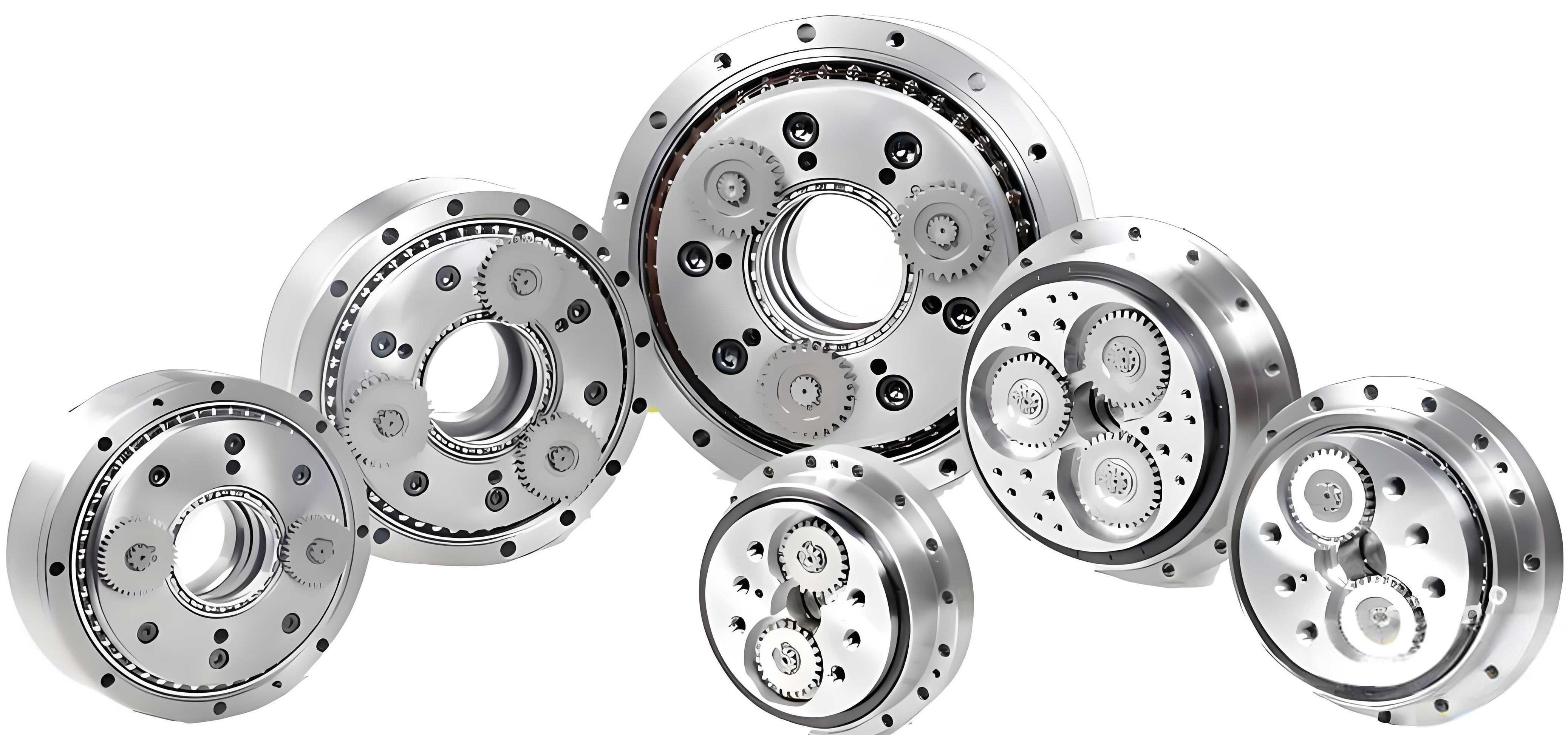
The operational principle of a typical rotary vector reducer involves a fixed pin gear housing. The input shaft, integrated with the central sun gear, is driven by an external motor. This central gear meshes with and drives multiple spur gears (planetary gears). These spur gears revolve around the central gear (planet carrier rotation), constituting the first-stage speed reduction. Each spur gear is connected to a crank shaft. The rotation of the spur gears drives the crank shafts, which in turn drive paired cycloidal gears with a 180° phase difference. The meshing between the cycloidal gears and the stationary pin teeth on the housing achieves the second-stage reduction. The first-stage transmission, being directly connected to the drive motor, imposes high demands on the dynamic characteristics of its central and spur gears. Fatigue fracture and tooth surface wear of the spur gears are primary failure modes in such transmissions. Therefore, analyzing their modal characteristics under actual meshing conditions is a prerequisite for optimizing and enhancing the performance of the entire rotary vector reducer.
Theoretical Background for Modal Analysis
The dynamic behavior of a mechanical structure like a gear can be described by its equations of motion. For a multi-degree-of-freedom linear system, the undamped free vibration equation is given by:
$$
\mathbf{[M]}\{\ddot{x}\} + \mathbf{[K]}\{x\} = \{0\}
$$
where \(\mathbf{[M]}\) is the mass matrix, \(\mathbf{[K]}\) is the stiffness matrix, \(\{\ddot{x}\}\) is the acceleration vector, and \(\{x\}\) is the displacement vector. The solution to this eigenvalue problem yields the natural frequencies (eigenvalues, \(\omega_n\)) and the corresponding mode shapes (eigenvectors, \(\{\phi_n\}\)), satisfying:
$$
(\mathbf{[K]} – \omega_n^2 \mathbf{[M]}) \{\phi_n\} = \{0\}
$$
In the context of a spur gear within a rotary vector reducer, the mass matrix \(\mathbf{[M]}\) is derived from its geometry and material density. The stiffness matrix \(\mathbf{[K]}\), however, varies drastically between a free state and a constrained, meshing state. In the free state, the stiffness is governed solely by the gear’s material and structural geometry. When the gear is assembled and meshing, additional stiffness contributions arise from:
- Tooth Mesh Stiffness: The time-varying contact stiffness at the interface with the central sun gear.
- Support Stiffness: The constraints provided by the splined connection to the crank shaft and the indirect support through bearings.
- Boundary Conditions: The kinematic constraints from the planetary carrier and the mating gear.
These added constraints significantly alter the system’s stiffness matrix, leading to changes in its natural frequencies and mode shapes compared to the free state. Modal analysis via the Finite Element Method (FEM) is employed to solve this complex eigenvalue problem for both configurations.
Finite Element Model Development and Methodology
This analysis is based on the model of an RV-40E rotary vector reducer. The three-dimensional model of the first-stage planetary transmission, comprising the central sun gear input shaft and two spur gears, was created. The spur gear of interest is made of 20CrMnTi alloy steel. The material properties assigned for the finite element analysis are summarized below:
| Material Property | Symbol | Value | Unit |
|---|---|---|---|
| Density | \(\rho\) | 7800 | kg/m³ |
| Young’s Modulus | \(E\) | 2.07 x 10¹¹ | Pa |
| Poisson’s Ratio | \(\mu\) | 0.25 | – |
Two distinct finite element models were developed:
- Free-State Spur Gear Model: A single, unconstrained spur gear model was meshed using hexahedral elements with a global size of 1 mm. The model resulted in 229,074 nodes and 65,432 elements.
- Meshed-State Planetary Train Model: The full planetary assembly model was meshed. The central gear and spur gears had a global mesh size of 1 mm, while the contacting tooth surfaces were refined to 0.5 mm to better capture contact behavior. The final assembly mesh contained 844,760 nodes and 240,657 elements.
The boundary conditions for the meshing state simulation were defined to replicate the actual working conditions within the rotary vector reducer:
- Central Sun Gear: All degrees of freedom were fixed except for rotation about its central axis (Z-axis).
- Spur Gears: The connection to the crank shaft was modeled as a remote displacement constraint, fixing radial and axial movements while allowing rotation (tangential freedom). The contact surfaces between the spur gear teeth and the central gear teeth were defined as “Bonded” for the modal analysis, representing the instant of maximum contact engagement. This approach captures the stiffening effect of the meshing teeth for a specific engagement position.
- System Context: The analysis implicitly considers the spur gear’s connection to the crank shaft, which is itself supported by bearings within the planetary carrier, adding further constraint stiffness.
A modal analysis (Block Lanczos solver) was performed on both models to extract the first ten natural frequencies and their corresponding mode shapes.
Results: Free-State Modal Characteristics
The first ten natural frequencies and a description of the dominant modal deformation for the unconstrained spur gear are presented in the table below. The mode shapes are classified based on the observed deformation patterns of the gear body and teeth.
| Mode Order | Natural Frequency (Hz) | Mode Shape Description |
|---|---|---|
| 1 | 10,868 | Two-diameter (2 nodal diameter) in-plane bending |
| 2 | 17,927 | Axial “umbrella” mode (coning) |
| 3 | 24,649 | Three-diameter in-plane bending |
| 4 | 28,907 | Radial symmetric expansion/contraction |
| 5 | 33,719 | Axial torsional mode |
| 6 | 39,218 | Four-diameter in-plane bending |
| 7 | 48,165 | Coupled radial and torsional deformation |
| 8 | 49,496 | Radial breathing mode |
| 9 | 53,851 | Five-diameter in-plane bending |
| 10 | 57,400 | Higher-order axial torsion |
The results indicate a progression of natural frequencies with increasing mode order. A key observation is that the primary deformation in most modes (especially the in-plane bending modes 1, 3, 6, 9) is concentrated in the gear teeth, which act as flexible cantilevers attached to the relatively rigid gear rim and web. The gear hub shows minimal deformation in these free-free modes. The sequence of modes follows a typical pattern for axisymmetric structures, alternating between families of in-plane bending (nodal diameters), axial, and radial modes.
Results: Meshed-State Modal Characteristics
The modal analysis of the spur gear within the constrained planetary train yields dramatically different results. The imposed boundary conditions from the central gear mesh and the crank shaft support drastically alter the system’s dynamic properties. The first ten natural frequencies and their characteristics for this assembled state are listed below.
| Mode Order | Natural Frequency (Hz) | Mode Shape Description (System View) |
|---|---|---|
| 1 | 1,277.6 | Symmetric mirror-image twisting of both spur gears about the central axis. |
| 2 | 5,116.2 | In-phase fore-aft swinging of both spur gears relative to the central gear. |
| 3 | 5,226.4 | Out-of-phase twisting vibration of the two spur gears. |
| 4 | 5,955.2 | Coupled torsion along the Z-axis and fore-aft vibration of the gear body. |
| 5 | 6,327.1 | Mirror-image rocking (bending) of both gears about an axis perpendicular to the line of centers. |
| 6 | 6,357.8 | In-plane “folding” deformation of the gear body along the Z-axis direction. |
| 7* | – | (Mode primarily in central gear or higher frequency) |
| 8* | – | (Mode primarily in central gear or higher frequency) |
| 9 | 7,173.6 | Bidirectional bending of both spur gears in opposite phases. |
| 10 | 8,320.5 | Bidirectional bending of both spur gears in the same phase. |
*Modes 7 and 8 in the system solution were dominated by deformation of the central gear and are omitted to focus on spur gear behavior.
The most striking finding is the significant reduction in natural frequencies when compared to the free state. For instance, the first natural frequency drops from 10,868 Hz (free) to 1,278 Hz (meshed), nearly an order of magnitude lower. This is a direct consequence of the added mass from connected components (crank shaft) and, more importantly, the change in effective stiffness. While the tooth mesh and supports add localized stiffness, they transform the gear from a free body to a constrained component within a larger, more compliant system. The overall system stiffness for these global modes (like the rocking and swinging of the entire gear body on its supports) is lower than the intrinsic bending stiffness of the free gear blank.
Detailed Analysis of Constrained Mode Shapes and Implications
The mode shapes under meshing conditions reveal critical information about dynamic weak points. In the third system mode (5,226 Hz), the spur gear exhibits a twisting vibration. The deformation cloud plot shows that the amplitude of vibration is not uniform across the gear. The teeth in direct mesh with the central gear show markedly smaller deformation due to the localized stiffening effect of the bonded contact. Conversely, teeth away from the immediate meshing zone, particularly those on the opposite side of the gear, experience larger amplitudes. This non-uniform deformation pattern highlights how the meshing interface dynamically “pins” a section of the gear.
The fifth system mode (6,327 Hz) shows both spur gears undergoing a mirror-image rocking motion. Again, the deformation is minimized in the region of the gear hub and near the central axis of constraint, while the outer rim and teeth exhibit larger motion. This is a clear signature of the gear vibrating as a rigid body on the flexible support provided by the crank shaft and bearing system, superimposed with elastic deformation.
The tenth mode (8,321 Hz) is particularly instructive. It involves both spur gears bending in the same direction. The maximum deformation occurs on the gear rim and teeth farthest from the gear’s center of rotation and the constraining influence of the central gear mesh. This identifies the rim and the teeth not in load-bearing contact at a given instant as potential dynamic weak areas where stress concentrations under operational dynamic loads might be highest. The constraint from the central gear and the crank shaft effectively creates a “fixed” region, forcing vibrational energy into the more “free” sections of the gear structure.
These observations have direct implications for the design and manufacturing of the rotary vector reducer:
- Resonance Avoidance: The operational speed range of the drive motor and the resulting meshing frequency (\(f_m = N \times \text{RPM} / 60\), where \(N\) is the number of teeth on the driving gear) must be carefully evaluated against the lower natural frequencies of the constrained system (e.g., ~1.3 kHz, ~5.1 kHz) to avoid resonance, which can lead to excessive noise, vibration, and accelerated fatigue failure.
- Emphasis on Assembly and Fit: The analysis underscores that the dynamic response is highly sensitive to the boundary conditions. Therefore, the quality of the spline fit between the spur gear and the crank shaft, the bearing stiffness supporting the crank shaft, and the precise alignment of the planetary train become critically important. Any looseness or deviation can alter the effective constraint stiffness, shifting natural frequencies and potentially degrading performance.
- Tooth Load Distribution: The non-uniform vibrational deformation suggests that dynamic tooth loads may not be evenly distributed across all teeth during operation. This reinforces the need for high-precision gear manufacturing and profile modifications to ensure smooth load sharing and minimize dynamic excitation.
Conclusion
This investigation conducted a comparative modal analysis of spur gears in both free and meshing states, as found in a precision rotary vector reducer. Using finite element methods, the study conclusively demonstrates that the operational dynamic characteristics of the spur gear are fundamentally different from its free-state properties. The key findings are:
- The natural frequencies of the spur gear in its assembled, meshing condition are significantly lower than those in the free state due to the system-level constraints imposed by the central gear mesh and the crank shaft support. The first mode frequency decreased by approximately 89%.
- The mode shapes shift from primarily gear-centric elastic deformations (like nodal diameter bending) to system-level motions involving the spur gear vibrating on its supports (e.g., rocking, swinging, system twisting), with superimposed elastic deformation of the gear body.
- The meshing interface with the central gear acts as a localized stiffener, reducing vibrational amplitude in the contacting teeth region. Consequently, the maximum dynamic deformation and stress under vibration are likely to occur in the gear rim and teeth sectors away from the immediate point of constraint, identifying them as areas requiring attention in design for dynamic loads.
This work provides crucial insights for the dynamic design of the first-stage transmission in a rotary vector reducer. The results highlight the necessity of performing modal and dynamic analyses on fully constrained system models rather than isolated components. Furthermore, they emphasize that achieving consistent and high-performance dynamic behavior relies not only on the design of individual gears but also on the precise control of assembly tolerances, fit characteristics, and bearing stiffness. Future work will extend this analysis to transient dynamic meshing simulations to evaluate dynamic transmission error and time-varying stress distributions under operational loads, further optimizing the performance and reliability of the rotary vector reducer.