
In the field of industrial robotics, the demand for high-performance and efficient components is ever-increasing. Among these, the rotary vector reducer plays a pivotal role as a core transmission component in robotic arms, providing high reduction ratios, compact structure, and superior stiffness. As a researcher focused on mechanical design and optimization, I have observed that the widespread adoption of rotary vector reducers in heavy-duty applications often comes with the drawback of excessive mass, which can burden robotic systems and limit their operational efficiency. Therefore, in this paper, I explore the implementation of topology optimization techniques to achieve lightweight design for key components of the rotary vector reducer, specifically the pin housing and planet carrier, while ensuring structural integrity and performance. This study is motivated by the need to enhance the power-to-weight ratio of robotic systems without compromising reliability, a critical aspect for advancing industrial automation.
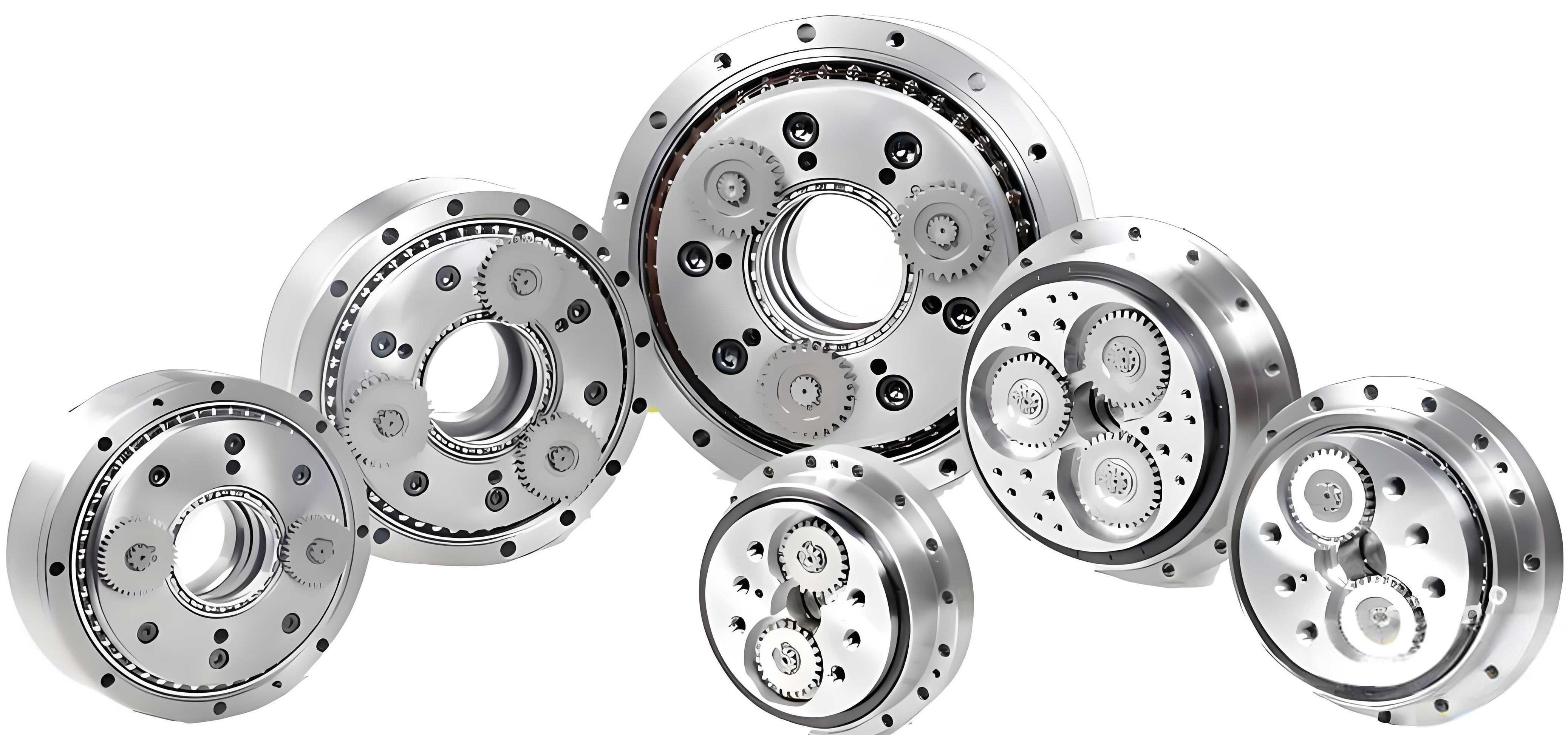
The rotary vector reducer, often abbreviated as RV reducer, is a two-stage closed transmission device that combines planetary gear transmission with cycloidal pin gear transmission. It evolved from traditional cycloidal pinwheel planetary reducers, addressing limitations such as eccentric vibrations. Its advantages include high precision, large transmission ratios, and smooth operation, making it indispensable in applications like CNC machine tools, semiconductor equipment, and precision manufacturing. However, the inherent complexity and material usage in rotary vector reducers contribute to significant weight, which can impede the dynamic response and energy efficiency of robotic arms. Hence, optimizing the mass of these reducers through advanced design methodologies like topology optimization is crucial. Topology optimization, a mathematical approach that determines the optimal material distribution within a design space under given constraints, has matured with computational tools, enabling efficient lightweight design without sacrificing strength.
To lay the foundation for optimization, I first conduct a detailed force analysis of the pin housing and planet carrier in the rotary vector reducer. These components are subjected to complex loads from bearings, crank shafts, and planetary gears during operation. For instance, angular contact ball bearings support radial and axial forces while transmitting moments and torques, whereas cylindrical roller bearings and tapered roller bearings handle additional radial and moment loads. The force interactions can be modeled using equilibrium equations. Let me denote the radial forces on angular contact ball bearings as \( F_{r1} \) and \( F_{r2} \), which induce derived axial forces \( F_{a1} \) and \( F_{a2} \) due to the bearing arrangement. The relationships can be expressed as:
$$ F_{a1} = \frac{F_{r1}}{2Y} \quad \text{and} \quad F_{a2} = \frac{F_{r2}}{2Y} $$
where \( Y \) is the axial load factor derived from bearing specifications. Similarly, for cylindrical roller bearings on the crank shaft, the forces \( F_{R1}, F_{R2}, F_{R3} \) are calculated based on the torque transmission from the cycloidal gear. Assuming a torque \( T_1 \) on one cycloidal gear, the force distribution among three crank shafts can be derived from static equilibrium:
$$ \sum_{i=1}^{3} F_{Ri} \cdot r = T_1 $$
where \( r \) is the effective radius. For tapered roller bearings, the support forces \( F_{0y}, F_{0z}, F_{1y}, F_{1z} \) are determined by resolving moments and forces on the crank shaft. After performing these calculations with input parameters typical for a medium-sized rotary vector reducer, I compile the results into a comprehensive table to summarize the force and moment values.
| Force/Moment | Value | Unit |
|---|---|---|
| \( F_{rR1} \) (Radial force on cylindrical roller bearing 1) | 24,776 | N |
| \( F_{rR2} \) (Radial force on cylindrical roller bearing 2) | 23,869 | N |
| \( F_{rT1} \) (Radial force on tapered roller bearing 1) | 593 | N |
| \( F_{rT2} \) (Radial force on tapered roller bearing 2) | 1,899.3 | N |
| \( F_{r1} \) (Radial force on angular contact ball bearing 1) | 24,783 | N |
| \( F_{r2} \) (Radial force on angular contact ball bearing 2) | 23,944.4 | N |
| \( F_{a1} \) (Axial force on angular contact ball bearing 1) | 35,136.66 | N |
| \( F_{a2} \) (Axial force on angular contact ball bearing 2) | 27,296.61 | N |
| \( T_0 \) (Input torque) | 23.2 | N·m |
| \( T_2 \) (Intermediate torque) | 11.6 | N·m |
| \( T_3 \) (Output torque) | 11.6 | N·m |
| \( F_{0y} \) (Force component on tapered roller bearing in y-direction) | 261 | N |
| \( F_{0z} \) (Force component on tapered roller bearing in z-direction) | 95 | N |
| \( F_{1z} \) (Force component on planetary gear in z-direction) | 132.9 | N |
| \( F_{1y} \) (Force component on planetary gear in y-direction) | 2,164.6 | N |
| \( F_{4z} \) (Force component on pin housing in z-direction) | -37 | N |
| \( F_{4y} \) (Force component on pin housing in y-direction) | 2,425.6 | N |
| \( F_{4} \) (Resultant force on pin housing) | 2,425.9 | N |
| \( F_{1} \) (Resultant force on planetary gear) | 2,168.6 | N |
With these forces established, I proceed to static analysis using finite element methods to evaluate the stress and deformation of the pin housing and planet carrier. I model the rotary vector reducer in CAD software, focusing on the assembly of key components. For material properties, I select common engineering materials: 45 steel for the planet carrier and HT350 cast iron for the pin housing, as their mechanical characteristics align with the operational demands of rotary vector reducers. The material properties are tabulated below.
| Material | Density (kg/m³) | Poisson’s Ratio | Elastic Modulus (Pa) |
|---|---|---|---|
| 45 Steel | 7.89 × 10³ | 0.269 | 2.09 × 10¹¹ |
| HT350 | 7.30 × 10³ | 0.270 | 1.45 × 10¹¹ |
In the static analysis environment, I apply boundary conditions and loads based on the force analysis. For the planet carrier, I fix all bolt holes to simulate mounting constraints. Pressure loads equivalent to the bearing forces are applied on the bearing contact surfaces: for example, on the angular contact ball bearing seats, radial pressures of 2.93 MPa and 3.3 MPa are applied, with additional axial pressures of 3.9 MPa and 16.7 MPa to account for derived axial forces. Similarly, tapered roller bearing seats receive pressures of 1.13 MPa and 1.41 MPa. After meshing with an element size of 5 mm and solving, I obtain deformation and von Mises stress results. The maximum deformation is 0.028599 mm at the edge of the planet carrier, induced by axial forces, while the maximum stress is 104.21 MPa at bolt holes, well below the yield strength of 45 steel (typically around 355 MPa). This confirms structural safety and indicates potential for mass reduction in the rotary vector reducer.
For the pin housing, I fix bolt holes and apply cylindrical supports on angular contact ball bearing seats with tangential freedom. Moments of 784 N·m are applied at the 40 pin tooth locations to simulate operational loads, and equivalent pressure loads of 2.58 MPa and 2.3 MPa are applied on bearing seats. The static analysis reveals a maximum deformation of 0.00018715 mm at pin tooth mounts and a maximum stress of 2.2936 MPa at bolt holes, far below the yield strength of HT350 (approximately 350 MPa). These results validate that both components in the rotary vector reducer have excess material, paving the way for topology optimization.
Topology optimization aims to remove material from low-stress regions while maintaining structural performance. I employ a density-based method, where the design variable is the material density at each point, ranging from 0 (void) to 1 (solid). The optimization problem is formulated to minimize compliance (a measure of flexibility) subject to a volume fraction constraint. Mathematically, this can be expressed as:
$$ \min_{\rho} c(\rho) = \mathbf{U}^T \mathbf{K} \mathbf{U} $$
$$ \text{subject to:} \quad \frac{V(\rho)}{V_0} \leq f, \quad 0 < \rho_{\min} \leq \rho \leq 1 $$
where \( c \) is compliance, \( \rho \) is the density vector, \( \mathbf{U} \) is the displacement vector, \( \mathbf{K} \) is the stiffness matrix, \( V \) is the volume, \( V_0 \) is the initial volume, \( f \) is the target volume fraction, and \( \rho_{\min} \) is a minimum density to avoid singularity. I set up the optimization in finite element software, defining the entire planet carrier and pin housing as design domains, while excluding non-design regions such as bearing contact surfaces and bolt holes to ensure functionality. For the planet carrier, 84 faces are excluded, and for the pin housing, 84 faces are excluded as well. The objective is to minimize compliance with a mass retention constraint of 70% for the planet carrier and 75% for the pin housing, determined through iterative trials to balance weight reduction and strength.
After solving, the topology optimization results show material removal patterns. For the planet carrier, large hollow regions appear in central areas where stress is low, with gray indicating retained material, brown as transition zones, and red as removed material. Similarly, the pin housing shows material removal from outer edges and low-stress zones. These results guide the redesign of components. I reconstruct the optimized geometries in CAD, preserving functional features like bearing seats and bolt holes, leading to lightweight versions of the planet carrier and pin housing for the rotary vector reducer.
To verify the optimized designs, I conduct another static analysis. The optimized planet carrier shows a maximum stress of 101.79 MPa, slightly lower than before, and the optimized pin housing shows a maximum stress of 2.3913 MPa. Both values remain within material limits, confirming that the lightweight rotary vector reducer maintains structural integrity. The mass reduction is significant: for the planet carrier, the mass decreases by approximately 25%, and for the pin housing, by about 20%, contributing to an overall lighter rotary vector reducer without compromising performance. This aligns with the goal of enhancing robotic arm efficiency.
In addition to static validation, I consider dynamic aspects such as modal analysis to ensure the optimized rotary vector reducer avoids resonant frequencies. The natural frequencies of the optimized components are calculated using the equation:
$$ (\mathbf{K} – \omega^2 \mathbf{M}) \mathbf{\phi} = 0 $$
where \( \mathbf{K} \) is the stiffness matrix, \( \mathbf{M} \) is the mass matrix, \( \omega \) is the angular frequency, and \( \mathbf{\phi} \) is the mode shape. The first few natural frequencies for the optimized planet carrier are above 500 Hz, and for the pin housing above 1000 Hz, which are sufficiently high to avoid operational excitation frequencies in typical industrial robots. This further supports the robustness of the lightweight design.
The optimization process highlights the effectiveness of topology optimization in redesigning rotary vector reducer components. By integrating force analysis, static validation, and optimization algorithms, I achieve a balanced approach to weight reduction. Future work could explore multi-objective optimization including thermal effects or fatigue life, and experimental testing to validate computational models. Nonetheless, this study demonstrates that topology optimization is a powerful tool for advancing the design of rotary vector reducers, contributing to more efficient and agile robotic systems in industrial applications.
In conclusion, through detailed force analysis, static finite element simulations, and density-based topology optimization, I have successfully implemented a lightweight design for the pin housing and planet carrier of a rotary vector reducer. The optimized components show reduced mass while maintaining stress levels below material yield strengths, ensuring reliability. This approach not only enhances the performance of the rotary vector reducer but also supports broader goals of energy efficiency and dynamic response in robotics. As industrial demands evolve, such optimization methodologies will be crucial for developing next-generation rotary vector reducers that are both lightweight and robust.