
In the field of industrial robotics, the RV reducer stands as a critical component, directly influencing the precision, stiffness retention, and operational lifespan of robotic systems. My extensive experience in analyzing and designing these precision drives has consistently highlighted a paradoxical challenge: while the planetary gear stage is not typically the primary life-limiting element, its failure modes can precipitate cascading damage that severely compromises the overall durability of the RV reducer. Through rigorous durability testing regimes, including constant load and disc-type cyclic tests, I have observed that contact fatigue wear particles generated from the planetary gear pairs migrate through the lubricating oil. These hard particles subsequently inflict rolling contact damage on the more critical components, namely the crankpin bearings and the cycloidal drive interfaces. This secondary damage accelerates failure in these sensitive areas, effectively curtailing the unit’s service life. Therefore, addressing the root cause of contact fatigue within the planetary gear pair is not merely an exercise in improving one sub-system; it is a vital strategy for enhancing the holistic longevity and reliability of the RV reducer. This article, drawn from my practical engineering work, will delve into the mechanisms of contact fatigue in this context, analyze the principal causes of uneven load distribution, and detail effective gear modification strategies that form a closed-loop improvement process. The insights and methodologies presented are intended to serve as a foundational reference for the design and refinement of planetary gear pairs across a series of RV reducer models.
Contact fatigue on gear tooth surfaces is a progressive material failure phenomenon initiated when the alternating subsurface shear stresses exceed the material’s endurance limit. In the context of an RV reducer’s planetary stage, this manifests as the pitting and spalling of metal from the tooth flanks of both the input sun gear and the planet gears. Based on the severity and morphology, tooth flank fatigue can be categorized into distinct stages. Early-stage pitting is characterized by small pits, typically 0.1 to 0.3 mm in diameter, and often self-arrests as the localized contact area increases. Destructive pitting involves larger, deeper pits that actively propagate and degrade transmission quality. Spalling refers to the flaking off of larger surface chunks, often linked to material imperfections or heat treatment issues, while case crushing or severe plastic deformation represents ultimate failure. The fatigue process is fundamentally governed by the maximum contact (Hertzian) stress, which for two cylindrical surfaces in line contact can be expressed as:
$$ \sigma_{H} = \sqrt{\frac{F_t}{b \cdot \rho_{rel}} \cdot \frac{1}{\pi \cdot m_E}} $$
where the reduced radius of curvature $\rho_{rel}$ and the equivalent elastic modulus $m_E$ are given by:
$$ \frac{1}{\rho_{rel}} = \frac{1}{\rho_1} \pm \frac{1}{\rho_2} \quad \text{and} \quad m_E = \frac{1}{\frac{1-\nu_1^2}{E_1} + \frac{1-\nu_2^2}{E_2}} $$
In these equations, $F_t$ is the tangential tooth force, $b$ is the face width, $\rho$ denotes the radius of curvature at the contact point, and $E$ and $\nu$ are the Young’s modulus and Poisson’s ratio of the mating materials, respectively. The service life under contact fatigue is often modeled using a power law relation like the Lundberg-Palmgren theory, adapted for gears:
$$ L_{10} = \left( \frac{C_H}{\sigma_{H}} \right)^p $$
Here, $L_{10}$ is the rated life (number of stress cycles) with 90% reliability, $C_H$ is a material and geometry constant, and $p$ is the life exponent (typically around 6-9 for bearing steel). My observations from dissecting RV reducers after accelerated life tests clearly show that pitting on the planetary gear teeth is not uniformly distributed across the face width. Instead, it exhibits a pronounced bias toward one end of the tooth, specifically the end closer to the supporting bearing. This pattern is a classic signature of misalignment-induced edge loading or偏载接触 (partial load contact). The following table summarizes the typical fatigue damage observed under different test protocols for a specific RV reducer model (e.g., 500N series):
| Test Type | Duration (Hours) | Observed Fatigue Stage on Sun Gear | Load Condition |
|---|---|---|---|
| Constant Load | 7,407 | Spalling/Destructive Pitting | 2.5 x Rated Torque |
| Constant Load | 6,436 | Destructive Pitting | 2.5 x Rated Torque |
| Disc-Type Cyclic | 4,601 | Early-Stage Pitting | ±2.5 x Rated Torque (Sinusoidal) |
This non-uniform contact pattern directly increases the local $\sigma_H$, drastically reducing the $L_{10}$ life according to the power law. Furthermore, the generated wear debris acts as a contaminant in the oil, abrading the high-precision surfaces of the crank shaft rollers and cycloidal discs, which are paramount for the RV reducer’s performance. Thus, mitigating偏载接触 (partial load contact) in the planetary stage is a multiplier for improving the entire RV reducer’s durability.
To understand the root causes of this偏载接触 (partial load contact), one must first examine the unique architecture of the RV reducer. The RV reducer achieves high reduction ratios through a two-stage process: a primary planetary differential stage and a secondary cycloidal (or摆线) stage. The input power is transmitted via the sun gear (input shaft) to three planet gears spaced 120° apart. Unlike a standard planetary gearset, this stage lacks an internal ring gear. Each planet gear is internally splined and mounted onto an eccentric crankpin of a曲柄轴 (crank shaft). The rotation of the sun gear drives the planets, which in turn cause the eccentric crankpins to orbit. This orbital motion is then converted into reduced rotational output via the interaction between the cycloidal discs and the stationary pin gear housing. The critical support configuration is as follows: the input sun gear is typically supported by a single deep-groove ball bearing, allowing a degree of floating for self-alignment. Conversely, each planet gear is mounted in a cantilevered fashion onto its crankpin, which itself is supported by two tapered roller bearings within the planet carrier.
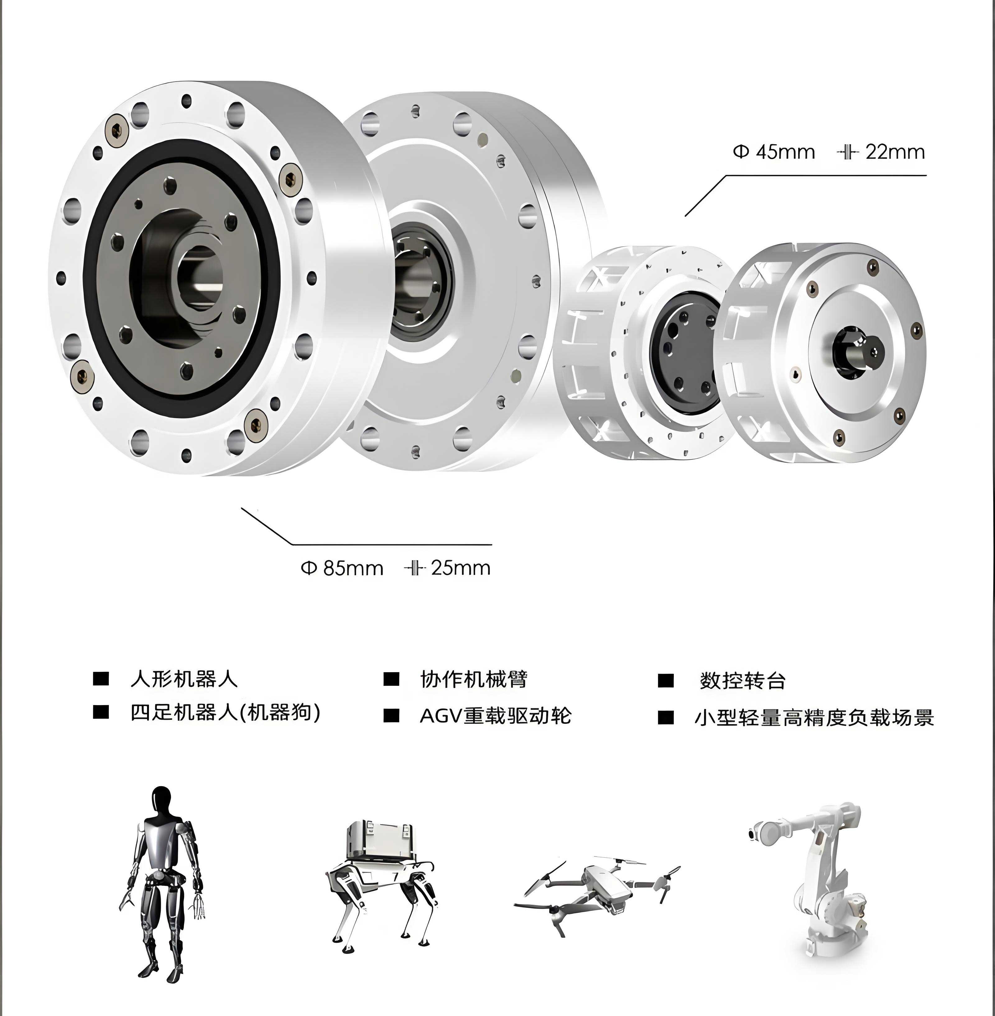
In an ideal, perfectly manufactured and assembled RV reducer, the three planet gears share the input load equally. The radial forces from the planets on the sun gear would sum to zero, and the tangential forces would perfectly transmit torque. However, real-world manufacturing tolerances and assembly variations disrupt this ideal equilibrium, leading to significant load sharing inequality. The primary contributors to this不均载 (unequal load distribution) are:
- Planet Carrier Bore Tolerances: The three bores in the planet carrier that house the crankpin bearings have inherent geometric errors. These include position error (deviation from true 120° spacing) and parallelism error between the two bearing seats for each crankpin axis. If the axes of the three crankpins are not perfectly parallel and symmetrically positioned, the planet gears will not mesh uniformly with the sun gear.
- Planet Gear Phase Consistency Error: Each planet gear has an external tooth flank and an internal spline. There is an angular phase relationship between these two features. If the three planet gears have inconsistent phase angles (i.e., the tooth on one planet is clocked differently relative to its spline compared to the others), they will not engage with the sun gear simultaneously at the same mesh point, causing uneven load distribution. This error can be reduced by grinding the teeth of all three planets as a stack, but some residual error remains.
- Spline Fit Clearance Variation: The internal spline of the planet gear and the external spline on the crankpin are typically a transition fit for ease of assembly. Variations in the manufacturing precision of these splines and the resulting clearance in each of the three fits lead to微小角位移 (micro-angular displacements), exacerbating phase inconsistencies.
- Crankpin Spline-to-Eccentric Phase Error: The crankpin is a complex component where the external spline (machined by precision hobbing) and the eccentric journal (finished by super-grinding) must have a precise angular relationship. Multi-step machining processes can introduce an angular deviation between these two features, meaning the theoretical centerline of the planet gear relative to the crankpin’s eccentric throw is not constant for all three units.
The cumulative effect of these errors is that the vector sum of the radial reaction forces from the three planet gears on the sun gear is not zero. This net radial force, $F_{radial}^{net}$, is proportional to the input torque $T_{in}$ and can be modeled as:
$$ F_{radial}^{net} = k \cdot \frac{T_{in}}{r_{bs}} $$
where $k$ is a dimensionless factor encapsulating all alignment errors (0 in a perfect system), and $r_{bs}$ is the base circle radius of the sun gear. This net force acts as a bending load on the sun gear shaft. Since the sun gear is supported by a single bearing at one end (a cantilevered condition), this force causes the gear to deflect, tilting it slightly. This tilt leads to a concentration of contact pressure at the tooth end closest to the bearing support, creating the observed偏载接触 (partial load contact) pattern. The load distribution along the face width becomes highly non-uniform, characterized by the face load factor $K_{H\beta}$. In severe cases, one end of the tooth carries the majority of the load, while the opposite end may even lose contact.
To quantitatively verify this failure mechanism and guide the improvement process, I employ advanced gear analysis software like MASTA for simulation. A detailed digital twin of the RV reducer’s planetary stage is created, incorporating nominal geometries, material properties, and most importantly, the statistical ranges of the manufacturing errors listed above. The analysis follows a Loaded Tooth Contact Analysis (LTCA) workflow to calculate the true contact pattern, pressure distribution, and bending stresses under load. The core of the LTCA solves the system of compatibility and equilibrium equations for the meshing teeth, which can be conceptually represented as finding the contact deformation $\delta_i$ at each potential contact point *i* that satisfies:
$$ \mathbf{K} \cdot \boldsymbol{\delta} = \mathbf{F} – \mathbf{g} $$
Here, $\mathbf{K}$ is the combined stiffness matrix of the gear teeth and shafts, $\boldsymbol{\delta}$ is the vector of contact deformations, $\mathbf{F}$ is the vector of applied tooth forces, and $\mathbf{g}$ is the vector of initial separations (geometric errors and modifications). Solving this yields the load distribution. For an unmodified gearset with the described errors, the LTCA results for a sample 500N-class RV reducer under high load reveal critical issues, as summarized below:
| Component | Max. Contact Stress $\sigma_{H_{max}}$ (MPa) | Face Load Factor $K_{H\beta}$ | Bending Safety Factor $S_F$ | Contact Safety Factor $S_H$ |
|---|---|---|---|---|
| Input Sun Gear | 1,767 | 2.26 | 0.84 | — |
| Planet Gear | 1,495 | 2.26 | 1.16 | 2.81 |
The results are alarming: the contact stress on the sun gear far exceeds the allowable limit for typical case-hardened gear steels (approx. 1,500 MPa), explaining the rapid onset of pitting. The high $K_{H\beta}$ value quantitatively confirms severe偏载接触 (partial load contact). Furthermore, the bending safety factor $S_F$ for the sun gear falls below 1.0, indicating a high risk of tooth breakage. This simulation conclusively pinpoints the need for corrective action centered on improving load distribution.
The most direct and effective engineering solution to counteract the effects of system misalignment and achieve uniform load distribution is strategic gear tooth modification, or修形. The goal of修形 (modification) is to intentionally alter the ideal tooth geometry to compensate for anticipated deflections and misalignments, thereby promoting a central, full-face-width contact pattern under operating load. For the planetary gear pair in an RV reducer, two primary types of modification are essential: profile modification and lead modification. Profile modification alters the tooth shape in the profile direction (along the depth of the tooth), while lead modification alters it in the lengthwise direction (across the face width).
For the observed偏载接触 (partial load contact) pattern where load concentrates at one end, a combination of lead modifications is required. A lead crown (barreling) is applied to center the contact patch, but this alone is insufficient for strong cantilever tilt. Therefore, a lead slope (or taper) is superimposed. The slope direction must be calculated to offset the specific tilt induced by the net radial force. In our case, the slope is applied to effectively “steer” the contact toward the center from the heavily loaded bearing-end. The total lead modification $\delta_{lead}(y)$ at a distance $y$ from the gear center can be described as the sum of a linear slope and a parabolic crown:
$$ \delta_{lead}(y) = C_{slope} \cdot \left(\frac{y}{b/2}\right) + C_{crown} \cdot \left(\frac{2y}{b}\right)^2 $$
where $b$ is the face width, $C_{slope}$ is the magnitude of the linear slope modification at the ends (in microns), and $C_{crown}$ is the magnitude of the parabolic crown at the ends. The optimal values for $C_{slope}$ and $C_{crown}$ are derived iteratively through LTCA simulations, aiming to minimize $K_{H\beta}$ and $\sigma_{H_{max}}$. Additionally, a small profile crowning is often applied to accommodate potential misalignment in the profile plane and to avoid edge loading at the tip or root. The profile modification $\delta_{profile}(x)$ is typically parabolic:
$$ \delta_{profile}(x) = C_{profile} \cdot \left(\frac{2x}{L_{act}}\right)^2 $$
Here, $x$ is the distance from the pitch point along the line of action, $L_{act}$ is the active length of the line of action, and $C_{profile}$ is the crown amount. Applying these modifications—specifically a lead slope combined with lead crown and profile crown—to the sun gear teeth transforms the contact pattern. Post-modification LTCA analysis under the same loading conditions shows dramatic improvement. The contact patch shifts to the center of the tooth face, and the pressure distribution becomes nearly uniform. The quantitative gains are evident in the following comparison table, which contrasts the performance of the unmodified gears with the optimally modified gears under two load conditions: 2.5 times and 5 times the rated torque.
| Condition | Component | Max. Contact Stress $\sigma_{H_{max}}$ (MPa) | Face Load Factor $K_{H\beta}$ | Bending Safety Factor $S_F$ | Contact Safety Factor $S_H$ |
|---|---|---|---|---|---|
| Unmodified (2.5x Load) |
Sun Gear | 1,767 | 2.26 | 0.84 | — |
| Planet Gear | 1,495 | 2.26 | 1.16 | 2.81 | |
| Modified (2.5x Load) |
Sun Gear | 1,244 | 1.12 | 1.22 | 4.75 |
| Planet Gear | 1,052 | 1.12 | 1.64 | 4.90 | |
| Modified (5.0x Load) |
Sun Gear | 1,892 | 1.18 | 0.95 | 2.11 |
| Planet Gear | 1,598 | 1.18 | 1.28 | 2.17 |
The improvements are substantial. The maximum contact stress is reduced by approximately 30% at the 2.5x load condition, bringing it well below the material’s endurance limit. The face load factor $K_{H\beta}$ drops from a critical 2.26 to an excellent 1.12, indicating virtually uniform load distribution. Consequently, both the bending and contact safety factors increase significantly, with $S_F$ for the sun gear rising above 1.0 to a safe 1.22. Furthermore, the transverse contact ratio, a measure of smoothness of power transmission, showed a measurable increase from a theoretical 1.32 to about 1.4, enhancing meshing continuity and reducing noise and vibration. This modification strategy effectively decouples the gear mesh sensitivity from the systemic alignment errors inherent in the RV reducer assembly, creating a robust design.
In conclusion, the pursuit of extended durability and reliability in RV reducers necessitates a proactive focus on the planetary gear stage, despite it not being the theoretical weakest link. The phenomenon of偏载接触 (partial load contact), driven by the accumulation of minute manufacturing and assembly tolerances within the complex RV reducer architecture, acts as a catalyst for premature contact fatigue. This fatigue generates deleterious wear debris that propagates failure to other critical components. Through a systematic analysis leveraging advanced simulation tools like MASTA, the root causes can be isolated and quantified. Strategic gear tooth修形 (modification), particularly a tailored combination of lead slope and crowning, emerges as a highly effective and manufacturable solution. It transforms a stress-concentrated, edge-loaded condition into a benign, centrally loaded contact pattern, dramatically reducing contact stress, improving load sharing, and boosting all relevant safety factors. This approach forms a closed-loop design-and-validation process that is directly scalable. For other models in the RV reducer series, such as the 42N, 60N, 100N, 125N, 160N, and 700N, the same fundamental principles apply. The specific magnitudes of lead slope ($C_{slope}$), lead crown ($C_{crown}$), and profile crown ($C_{profile}$) must be recalculated based on each model’s unique geometry, stiffness, bearing arrangement, and load spectrum. These values are then refined through prototype testing and life validation, creating an iterative database of经验 (empirical knowledge) that continuously informs and optimizes the design of future RV reducer generations. Therefore, mastering the art and science of planetary gear修形 (modification) is a cornerstone for any endeavor aimed at achieving world-class performance and longevity in precision RV reducers.