
The transmission accuracy and dynamic performance of industrial robots and high-precision machine tools are critically dependent on the performance of their core drive components. Among these, the RV reducer has emerged as a pivotal technology due to its exceptional combination of high reduction ratio, compact size, robust load capacity, and excellent torsional stiffness. The operational excellence of the RV reducer is fundamentally governed by the dynamic behavior of its cycloidal gear. This component is subjected to complex time-varying loads and excitations during service. Therefore, a thorough understanding of its vibration characteristics, including natural frequencies and mode shapes, is paramount for optimizing design, enhancing dynamic stability, minimizing noise and vibration, and preventing premature fatigue failure.
This article presents a detailed methodology for the dynamic characteristic analysis of the cycloidal gear within an RV reducer. The process begins with the creation of a precise parametric model, proceeds through the establishment of a finite element model, and culminates in a comprehensive modal analysis. The primary objective is to establish a foundational framework that can guide the structural optimization of the cycloidal gear, thereby contributing to the overall enhancement of the RV reducer’s dynamic performance and operational lifespan.
Transmission Principle of the RV Reducer
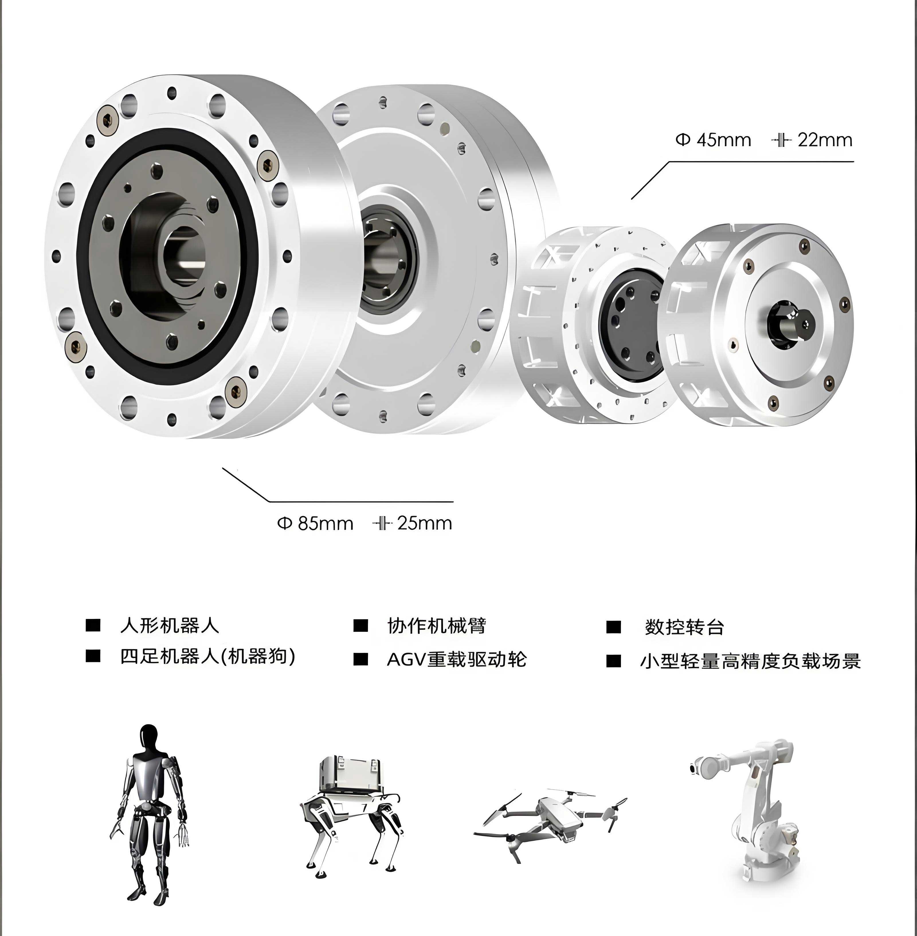
The RV reducer operates on a two-stage transmission principle, ingeniously combining a planetary gear stage with a cycloidal-pin wheel stage to achieve high reduction ratios in a compact envelope. The schematic diagram below illustrates the typical configuration and power flow within an RV reducer.
First Stage (Planetary Gear Stage): The input is provided by a sun gear (often integral with the input shaft). This sun gear meshes with multiple planet gears. This stage provides an initial speed reduction.
Second Stage (Cycloidal-Pin Wheel Stage): This is the core reduction stage. Each planet gear is connected to a crankshaft. Two cycloidal gears, offset by 180° for balance, are mounted on these crankshafts via roller bearings. The cycloidal gears mesh with a stationary ring of pin teeth (the pin wheel) housed in the casing. As the crankshafts rotate, they impart an eccentric motion to the cycloidal gears. Due to the difference in tooth count between the cycloidal gear and the pin wheel, the meshing causes the cycloidal gear to undergo a slow reverse rotation relative to the crankshaft’s revolution.
Output: This reverse rotation is transmitted to the output flange through pins or holes in the cycloidal gears. The final output speed is significantly lower than the input speed, with the total reduction ratio being the product of the ratios from both stages. The unique design of the RV reducer ensures high rigidity and excellent overload capacity, making it indispensable for precision applications.
Parametric Modeling of the Cycloidal Gear
The accuracy of any subsequent dynamic analysis is heavily contingent upon the geometric fidelity of the computational model. For the cycloidal gear, this necessitates a precise parametric definition of its complex tooth profile.
Mathematical Foundation: The Cycloidal Tooth Profile
The tooth profile of a standard cycloidal gear is generated by the trace of a point on the circumference of a rolling circle (generating circle) as it rolls without slippage on the inside of a base circle (the pin wheel center circle). For the RV reducer, the profile is typically an equidistant curve (offset) of this generated trochoid. The parametric equations for the modified cycloidal tooth profile can be derived in the Cartesian coordinate system as follows.
First, the coordinates of the theoretical generating point on the trochoid are given by:
$$ x_t = R_z [\sin(\theta) – K_1 \sin((Z_c + 1)\theta / Z_b)] $$
$$ y_t = R_z [\cos(\theta) – K_1 \cos((Z_c + 1)\theta / Z_b)] $$
where:
- $R_z$ is the radius of the pin center circle.
- $Z_c$ is the number of teeth on the cycloidal gear.
- $Z_b$ is the number of pins (teeth on the pin wheel), with $Z_b = Z_c + 1$.
- $K_1$ is the modification coefficient (also called the short width coefficient), defined as $K_1 = e \cdot Z_b / R_z$, where $e$ is the eccentricity.
- $\theta$ is the rolling angle parameter, typically ranging from $0$ to $2\pi$.
The unit normal vector components at this point, pointing towards the center of curvature (necessary for creating the equidistant offset for the roller pins), are:
$$ n_x = \frac{-K_1 \sin[(Z_c + 1)\theta] + \sin(\theta)}{\sqrt{1 + K_1^2 – 2K_1 \cos(Z_c \theta)}} $$
$$ n_y = \frac{-K_1 \cos[(Z_c + 1)\theta] + \cos(\theta)}{\sqrt{1 + K_1^2 – 2K_1 \cos(Z_c \theta)}} $$
Finally, the coordinates of the actual working tooth profile (the equidistant curve offset by the pin radius $r_z$) are:
$$ x = x_t + r_z \cdot n_x $$
$$ y = y_t – r_z \cdot n_y $$
$$ z = 0 $$
The sign in the y-coordinate offset depends on the direction of the normal vector chosen. This set of equations defines the precise contour of the cycloidal gear tooth.
Implementation for RV-40E
For this study, an RV-40E type reducer’s cycloidal gear is used as an exemplar. Its key geometric parameters are summarized in the table below.
| Parameter | Symbol | Value | Unit |
|---|---|---|---|
| Number of Pin Teeth | $Z_b$ | 40 | – |
| Number of Cycloidal Gear Teeth | $Z_c$ | 39 | – |
| Eccentricity | $e$ | 1.5 | mm |
| Pin Center Circle Radius | $R_z$ | 66.0 | mm |
| Pin Radius | $r_z$ | 3.0 | mm |
| Modification Coefficient | $K_1$ | $(e \cdot Z_b)/R_z \approx 0.9091$ | – |
Using a modern CAD software suite (e.g., SolidWorks), the parametric equations are implemented via the “Equation Driven Curve” tool within the sketching environment. By inputting the formulas for `x(θ)` and `y(θ)` with `θ` as a parameter from `0` to `2π`, a precise 2D sketch of the tooth profile is generated. A circular pattern of this single tooth profile, repeated $Z_c$ times, creates the full gear contour. This sketch is then extruded to create a solid 3D model of the cycloidal gear, incorporating other features like the bearing bore and output pin holes. The parametric nature of this model allows for rapid design iteration; modifying any primary parameter (e.g., $R_z$, $e$, $Z_c$) automatically updates the entire gear geometry, providing an excellent foundation for optimization studies of the RV reducer’s core component.
Finite Element Modal Analysis
Modal analysis is a fundamental technique in structural dynamics used to determine the inherent vibration characteristics of a component: its natural frequencies (eigenvalues) and mode shapes (eigenvectors). These properties are intrinsic to the structure’s geometry, material, and boundary conditions, and are independent of external loads. Identifying these modes is crucial for avoiding resonance, where operational excitation frequencies coincide with natural frequencies, leading to excessive vibrations and potential failure.
Preprocessing: Model Setup
The 3D parametric solid model is imported into a Finite Element Analysis (FEA) software (ANSYS is used as a reference). The analysis setup involves several critical steps:
1. Material Properties: The cycloidal gear is typically manufactured from high-carbon chromium bearing steel (e.g., GCr15/SAE 52100) for its high hardness, wear resistance, and fatigue strength. The linear-elastic, isotropic material properties are defined as shown in Table 2.
| Property | Symbol | Value | Unit |
|---|---|---|---|
| Young’s Modulus (Elasticity) | $E$ | 2.06 × 10¹¹ | Pa |
| Poisson’s Ratio | $\nu$ | 0.277 | – |
| Density | $\rho$ | 7830 | kg/m³ |
2. Element Type and Meshing: A higher-order 3D solid element with quadratic displacement behavior, such as SOLID186 in ANSYS, is selected. This 20-node hexahedral element is well-suited for modeling complex curved geometries and provides good accuracy for stress and deformation analysis. A fine, curvature-respecting mesh is generated on the model. Special attention is paid to the tooth profiles and fillet regions where stress concentrations are likely. A typical high-quality mesh for this study consists of approximately 57,000 elements and 93,000 nodes.
3. Analysis Type: A Modal analysis type is specified. The Block Lanczos eigenvalue extraction method is often employed for its efficiency and reliability in extracting a range of modes from medium to large-sized models.
Free Modal Analysis (Unconstrained)
This analysis assumes the cycloidal gear is in free space with no constraints applied. While this does not represent its operational state, it reveals the intrinsic dynamic properties of the gear structure itself, which are valuable for understanding its basic behavior and for component-level benchmarking. The first ten natural frequencies and their corresponding dominant mode shapes are extracted and summarized below.
| Mode Order | Natural Frequency (Hz) | Descriptive Mode Shape |
|---|---|---|
| 1 | 1430.5 | Torsional vibration about the Y-axis. |
| 2 | 1465.3 | Torsional vibration about the X-axis. |
| 3 | 2576.3 | Axial (Z-direction) expansion/contraction. |
| 4 | 3575.8 | Combined bending/torsion in the X-Y plane. |
| 5 | 3852.4 | Bending in the Y-Z plane. |
| 6 | 4264.6 | In-plane (X-Y) stretching deformation of the gear body. |
| 7 | 4729.5 | Out-of-plane (Y-Z) stretching deformation. |
| 8 | 5368.7 | Lateral bending along the X-axis. |
| 9 | 5579.6 | Lateral bending along the Y-axis. |
| 10 | 6752.1 | Complex coupled mode (X-axis torsion with Y-axis bending). |
The lower-order modes (1-3) are typically rigid-body-like modes (torsion, axial motion) which appear at finite frequencies due to the numerical approximation of the free condition. Higher-order modes (4-10) represent the gear’s flexible body deformations, including bending and combined bending-torsion shapes. The deformation is generally distributed across the entire gear body.
Constrained Modal Analysis
To simulate a more realistic operating environment, boundary conditions are applied to represent the gear’s connections within the RV reducer. Key constraints include:
- Crankshaft Bearing Bore: Displacement constraints are applied on the inner cylindrical surface of the central bore (where it fits onto the crankshaft bearing). Translations in the radial directions (X and Y) are typically constrained, while axial (Z) and rotational degrees of freedom may be left free or constrained depending on the bearing model.
- Pin Tooth Contact Regions: This is critical. The areas on the tooth flanks that are in potential contact with the pin teeth during meshing are identified. Normal displacements (perpendicular to the tooth profile at those points) are constrained to represent the kinematic restraint provided by the pin wheel. Since contact is not continuous over the entire tooth surface, constraints are often applied to a segment (e.g., half) of the theoretical contact zone on several teeth around the circumference to approximate the load-sharing condition.
Applying these constraints significantly stiffens the structure, leading to higher natural frequencies compared to the unconstrained case. The results for the first ten modes under these constrained conditions are presented below.
| Mode Order | Natural Frequency (Hz) | Descriptive Mode Shape |
| 1 | 2865.7 | Bending deformation, primarily along the X-axis direction. |
| 2 | 3425.5 | Torsional vibration about the X-axis. |
| 3 | 3866.5 | Bending deformation, primarily along the Y-axis direction. |
| 4 | 4713.7 | Combined in-plane (X-Y) bending and torsional deformation. |
| 5 | 6178.9 | Complex bending in the Y-Z plane. |
| 6 | 7269.5 | Higher-order in-plane distortion of the gear body. |
| 7 | 7774.6 | Out-of-plane (Y-Z) stretching and bending. |
| 8 | 8284.6 | Localized torsional deformation about the X-axis. |
| 9 | 8601.4 | Axial (Z-direction) deformation mode. |
| 10 | 8965.3 | Coupled high-order mode involving multiple deformation directions. |
A critical observation from the constrained analysis is the localization of high-strain energy regions. The mode shapes frequently show amplified deformation in the tooth roots and the thin sections of the gear body between the pin holes and the outer rim or central bore. These areas are identified as potential weak points susceptible to dynamic stress concentrations and fatigue initiation under operational vibration. For instance, Mode 1 (X-axis bending) and Mode 3 (Y-axis bending) clearly show bending stresses concentrating at the tooth roots opposite the direction of bending.
Discussion and Implications for RV Reducer Design
The comparative analysis of unconstrained and constrained modal results yields significant insights for the design and application of the cycloidal gear within the RV reducer system.
1. Frequency Shift and Stiffness: The natural frequencies under constrained conditions are substantially higher (often nearly double or more for corresponding mode orders) than those in the free state. This quantitatively demonstrates the significant stiffening effect provided by the crankshaft support and, more importantly, the kinematic constraint of meshing with the pin wheel. This increased stiffness is beneficial for pushing the resonant frequencies beyond the common operational excitation ranges of the RV reducer.
2. Critical Modes and Resonance Avoidance: The fundamental bending modes (Modes 1 & 3 in the constrained analysis, occurring around 2.8-3.9 kHz) are of particular concern. The input stage of an RV reducer, driven by a servo motor, can generate excitations at the meshing frequency of the planetary gears and its harmonics. The motor itself may also have inherent rotational harmonics. The designer must ensure that these excitation frequencies do not coincide with the identified low-order natural frequencies of the cycloidal gear to prevent resonance. For example, if an RV reducer with an input speed of 3000 rpm (50 Hz) has a first-stage reduction ratio of 3, the crankshaft speed is about 1000 rpm (16.67 Hz). The primary excitation from the second-stage cycloidal-pin meshing would be at $f_{mesh} = Z_c \times \text{crankshaft speed} = 39 \times 16.67 \text{ Hz} \approx 650 \text{ Hz}$. Comparing this to the first natural frequency of ~2866 Hz shows a comfortable margin, but higher harmonics (e.g., 3×, 5×) must also be checked.
3. Guide for Structural Optimization: The identified mode shapes act as a direct guide for optimization. To increase the lowest natural frequencies and improve dynamic stability, material can be strategically added to areas showing high deformation (e.g., reinforcing the gear web, optimizing the rim thickness). Conversely, to reduce weight without sacrificing critical frequency margins, material can be removed from areas of low deformation (low strain energy regions), such as certain sections of the central hub, provided static strength and stiffness requirements are still met. The parametric modeling approach is essential for efficiently exploring these design changes.
4. Foundation for Advanced Dynamics: The modal analysis results—frequencies and mass-normalized mode shapes—form the essential input for more sophisticated dynamic simulations of the entire RV reducer. They are used to construct a reduced-order dynamic model for forced-response analysis, such as studying the gear’s vibration response under time-varying transmission error loads or assessing its acoustic radiation characteristics. Understanding these dynamics is key to achieving the low-noise operation demanded by modern robotics.
Conclusion
This comprehensive study details a systematic engineering workflow for analyzing the dynamic characteristics of the cycloidal gear, a critical component determining the performance of an RV reducer. The integration of precise parametric modeling based on mathematical trochoidal geometry with high-fidelity finite element modal analysis provides a powerful tool for designers and engineers. The methodology successfully identifies the fundamental vibration modes and natural frequencies of the gear under both free and functionally constrained conditions.
The key findings underscore that the operational constraints within the RV reducer assembly significantly elevate the gear’s natural frequencies compared to its free state. The analysis pinpoints the gear tooth roots and thin web sections as regions most susceptible to dynamic deformation, highlighting them as focal points for structural optimization. By leveraging this approach, designers can proactively tailor the geometry of the cycloidal gear to shift its resonant frequencies away from operational excitation bands, enhance its dynamic stiffness, and reduce vibration amplitudes. This leads directly to improved positional accuracy, reduced noise, extended fatigue life, and greater overall reliability of the RV reducer system in demanding applications such as precision robotics and advanced machine tools. The established parametric and simulation framework serves as a robust foundation for future research into nonlinear dynamics, contact-impact analysis, and system-level multi-body dynamic simulation of the complete RV reducer transmission.