
High-modulus spur gears are critical components in transmission systems, such as those found in high-speed, heavy-duty vehicles. The traditional manufacturing routes for these gears primarily involve machining from solid blanks or hot closed-die forging. While machining can achieve the required dimensional accuracy and surface finish, it is inherently wasteful of material and time-consuming, leading to low production efficiency. On the other hand, hot closed-die forging offers high productivity, but the severe oxidation that occurs at high working temperatures significantly compromises the surface quality and dimensional precision of the final forging.
To address the limitations of these conventional methods, this article explores and advocates for the adoption of a warm forging process for manufacturing high-modulus spur gears. Warm forging, conducted at temperatures below the recrystallization point but high enough to reduce flow stress, presents a compelling alternative. It minimizes oxidation, improves dimensional accuracy, and can lead to superior mechanical properties compared to hot forging, while requiring less forming force than cold forging. The successful implementation of this process for complex geometries like spur gears hinges on meticulous process design and die optimization.
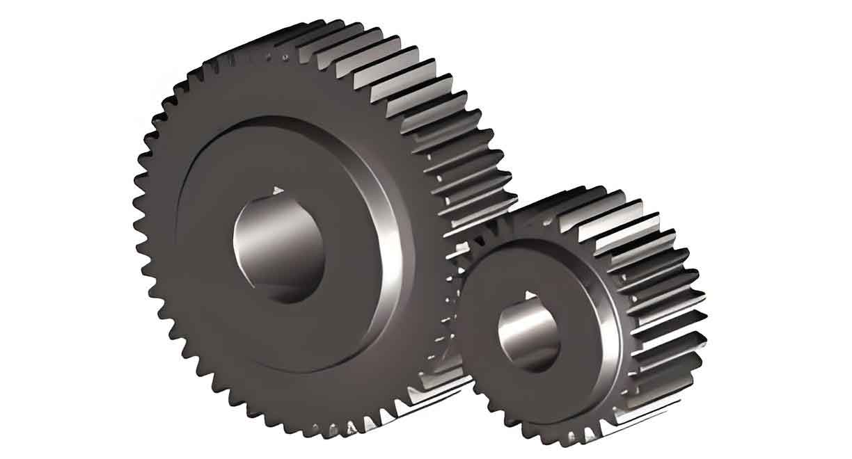
This study focuses on a specific high-modulus spur gear and employs the finite element analysis (FEA) software ABAQUS to simulate the entire forming process. The primary objectives are to analyze the initial die design, identify potential defects related to stress distribution and material flow, propose and validate an optimized die structure, and investigate the influence of key process parameters on the final quality of the forged spur gears. The ultimate goal is to establish a robust warm forging methodology that ensures complete die filling, uniform deformation, and high integrity of the spur gears.
1. Process Analysis and Initial Setup
1.1 Warm Forging Process Sequence
The proposed warm forging sequence for the spur gear is methodical. It begins with a solid cylindrical billet of appropriate dimensions. This billet undergoes preparatory steps like descaling to remove any rust or imperfections. It is then inductively heated to a precisely controlled warm forging temperature of 840°C. The heated billet is transferred to the forging die where it is formed under pressure. The resulting forging, while approximating the final spur gear shape, includes necessary features like machining allowances and a central web (flash). This web is subsequently removed via a punching operation. Finally, the forged preform undergoes finishing machining, heat treatment, and surface treatment to produce the finished, high-precision spur gear component.
The specific geometric parameters of the target spur gear are as follows:
- Gear Height: 65 mm
- Bore Diameter: 49 mm
- Normal Module: 8.22
- Number of Teeth: 18
- Addendum: 9.85 mm
- Dedendum: 5.67 mm
- Pitch Circle Diameter: 123.3 mm
- Pressure Angle: 20°
- Helix Angle: 0°
- Profile Shift Coefficient: 0.38
1.2 Material Selection and Initial Die Design
The material chosen for these high-performance spur gears is 40CrNiMoA alloy steel. This low-alloy steel is renowned for its excellent combination of strength, toughness, and hardenability, making it ideal for critical, high-stress components like gears, shafts, and heavy-duty fasteners. Its chemical composition and required mechanical properties are detailed in the tables below.
| C | Si | Mn | Cr | Ni | Mo | Cu | Fe |
|---|---|---|---|---|---|---|---|
| 0.40 | 0.30 | 0.70 | 0.70 | 1.40 | 0.20 | 0.15 | Bal. |
| Yield Strength (MPa) | Tensile Strength (MPa) | Elongation (%) | Hardness (HB) | Impact Energy (J) | Reduction of Area (%) |
|---|---|---|---|---|---|
| ≥ 835 | ≥ 980 | ≥ 12 | ≤ 269 | ≥ 78 | ≥ 55 |
Based on the gear geometry and material properties, an initial die concept was designed for the warm forging process. The initial die assembly functioned as follows: A stationary bottom ejector pin supported the billet. An upper die plate, driven by the press ram, moved downwards. This plate contacted and pushed a toothed inner die core, which was initially resisted by a compression spring. As the upper plate continued its stroke, the billet was compressed between the moving inner core and the stationary ejector, causing metal to flow radially into the tooth cavities, forming the spur gear shape with a central web.
The established process parameters for the initial simulation are summarized in the table below. The average deformation degree was calculated to be 35.8%, and the process was simulated for a 4000 kN hydraulic press.
| Parameter | Value | Unit |
|---|---|---|
| Billet Length | 45 | mm |
| Billet Diameter | 110 | mm |
| Billet Heating Temperature | 840 | °C |
| Die Preheat Temperature | 450 | °C |
| Heat Transfer Coefficient | 2200 | W/(m²·°C) |
| Average Deformation Degree | 35.8 | % |
| Press Speed / Ram Velocity | 0.65 | mm/s |
2. Numerical Simulation of the Initial Die Design
The forming process for the spur gears was simulated using ABAQUS/Explicit to handle the large deformations and complex contact conditions. The material behavior was modeled considering the temperature and strain-rate sensitivity typical of warm forging. The flow stress (σ) can be generically represented as a function of strain (ε), strain-rate (έ), and temperature (T):
$$ \sigma = f(\epsilon, \dot{\epsilon}, T) $$
A key metric for analyzing the results is the equivalent (Von Mises) stress, which is indicative of the deformation intensity and potential for defect formation. It is calculated from the stress tensor components (σ_ij) as:
$$ \sigma_{eq} = \sqrt{\frac{3}{2} s_{ij}s_{ij}} $$
where \( s_{ij} = \sigma_{ij} – \frac{1}{3}\sigma_{kk}\delta_{ij} \) is the deviatoric stress.
The simulation results for the initial die design revealed significant issues. The analysis focused on the cross-section of a single tooth, examining the distribution of equivalent stress and material flow velocity.
- Equivalent Stress Distribution: The stress field was highly non-uniform. The minimum equivalent stress, approximately 115 MPa, was located in the central rib/web area of the tooth cross-section. In stark contrast, the maximum equivalent stress, reaching up to 853 MPa, was concentrated at the tooth tip (addendum). This severe stress concentration at the tip is a critical concern as it can lead to excessive die wear, potential cracking during forging, and undesirable residual stresses in the final spur gears.
- Material Flow Velocity: The flow velocity of the deforming metal was also uneven. The highest velocity was observed at the tooth tip region, corresponding to the area of highest stress. This non-uniform flow can result in incomplete filling of the die corners (especially at the tooth root/fillet area) and may introduce flow lines or laps within the microstructure of the spur gears, negatively impacting their fatigue performance.
The root cause of these problems was traced to the kinematics of the initial die. The movement speed of the toothed inner core was dictated solely by the force balance between the upper plate and the compression spring. This led to an uncoordinated and uncontrolled flow of metal, particularly during the final stages of filling the tooth cavities, causing the observed stress concentrations and velocity gradients.
3. Optimization of the Die Structure
To overcome the limitations of the initial design, a fundamentally improved die structure was proposed. The new design incorporates active control of metal flow from both ends of the billet. The working principle is as follows: The billet is placed in the die cavity. An upper ejector pin moves downwards under the press force. Simultaneously, a lower ejector pin remains stationary or can be controlled. The metal is thus compressed and forced to flow radially from the center outwards into the tooth profiles of the stationary inner die core. This double-action scheme promotes a more symmetrical and controlled material flow.
The simulation of the forging process with this optimized die structure showed marked improvements:
- Equivalent Stress Distribution: The stress distribution became significantly more homogeneous across the tooth cross-section. The minimum stress increased to around 523 MPa in the web area, indicating more uniform work hardening. The maximum stress at the tooth tip was slightly higher at 866 MPa, but the gradient from the center to the tip was much less severe. This uniformity is crucial for dimensional stability after forging and for achieving consistent mechanical properties in the spur gears.
- Material Flow Velocity: The flow velocity field also showed better uniformity. While the tip region still exhibited the highest velocity, the difference compared to other regions was reduced. This leads to more simultaneous filling of the die cavity, minimizing the risk of defects and ensuring a sound microstructure throughout the forged spur gears.
4. Influence of Key Process Parameters on Forging Quality
While die structure is paramount, process parameters also critically influence the outcome. One key dimensional parameter within the die design is the thickness of the central web (flash). This study investigated the effect of web thickness on the dynamic response of the forming process, specifically the movement characteristics during forging.
Three different web thicknesses (10 mm, 20 mm, and 30 mm) were analyzed, keeping the distance from the web to the lower face of the gear constant. The metal flow lines for each case visually demonstrated the flow patterns.
The most insightful result came from analyzing the instantaneous velocity of the forming mass (or the relative die movement) as a function of the press stroke. The relationship between forming load (F), flow stress (σ), and instantaneous contact area (A) can be simplified as:
$$ F \approx \sigma_{flow} \cdot A $$
Changes in contact area and material flow resistance directly affect the reaction forces and hence the kinematics.
- 10 mm and 30 mm Web Thickness: For these asymmetric conditions (relative to the gear mid-plane), the velocity profile showed a distinct instability. After an initial steady phase, a sudden jump or change in velocity occurred during the stroke. This velocity jump corresponds to a sudden change in metal flow resistance, potentially caused by rapid filling of a cavity or a shift in the dominant deformation zone. Such instability is undesirable as it can lead to impact loading, uneven strain distribution, and reduced die life.
- 20 mm Web Thickness: This configuration, which provided a more symmetric constraint for metal flow, yielded a significantly smoother velocity profile. The movement remained stable and relatively constant throughout the forging stroke after the initial contact. This stable kinematic condition is optimal as it promotes steady, controllable metal flow, leading to more uniform deformation and higher quality spur gears with consistent properties.
5. Conclusion
This comprehensive study demonstrates the viability and advantages of using a warm forging process for manufacturing high-modulus spur gears. Through advanced numerical simulation using ABAQUS, critical flaws in an initial die design were identified, leading to the development of a superior, optimized double-action die structure.
- The optimized die structure for forging spur gears successfully achieves a more homogeneous distribution of equivalent stress and material flow velocity within the forged tooth geometry. The severe stress concentration at the tooth tip is mitigated, and the metal flows in a more controlled manner, which is essential for producing defect-free, high-integrity spur gears.
- The thickness of the central web is a critical process parameter influencing the dynamic stability of the forging process. A web thickness of 20 mm, which promotes symmetrical flow conditions, results in a stable and smooth forming velocity profile. In contrast, asymmetric web thicknesses (10 mm and 30 mm) lead to unstable velocity jumps, which are detrimental to the forging process and the final quality of the spur gears.
- The synergy between a properly designed die (the optimized structure) and correctly set process parameters (e.g., 20 mm web thickness) is fundamental to establishing a robust warm forging process. This approach offers a compelling alternative to traditional methods, promising high productivity, excellent material utilization, superior mechanical properties, and improved dimensional accuracy for high-performance spur gears used in demanding applications.
The findings provide a solid foundation for the design of production tools and the optimization of warm forging parameters for complex gear geometries, paving the way for more efficient and reliable manufacturing of critical transmission components like spur gears.