
In mechanical transmission systems, spur gears are widely used due to their simplicity and efficiency. However, the failure modes of spur gears, such as tooth breakage, pitting, and wear, are closely related to the load distribution and stress patterns during meshing. Accurately calculating the load and stress in involute spur gears is crucial for design optimization and durability assessment. In this article, we present a detailed method for calculating the load and stress in involute spur gears, based on deformation compatibility and advanced mechanical models. We address the complexities arising from alternating single and double tooth contact, varying meshing points, and elastic deformations. Our approach provides a precise way to analyze the mechanics of spur gears, and we demonstrate its application through a computational example.
The study of spur gear mechanics has been a focus in engineering research. Previous works have explored various aspects, including finite element models, Hertz contact theory, and load distribution algorithms. However, many existing methods simplify the gear geometry, assume simplified load distributions, or neglect the simultaneous meshing of multiple tooth pairs. For instance, some models consider only single tooth contact, while others approximate the tooth root fillet with circular arcs. These simplifications can lead to inaccuracies in stress calculations, particularly for high-precision spur gears. Our method aims to overcome these limitations by incorporating exact tooth profile equations, deformation compatibility, and comprehensive deformation analysis.
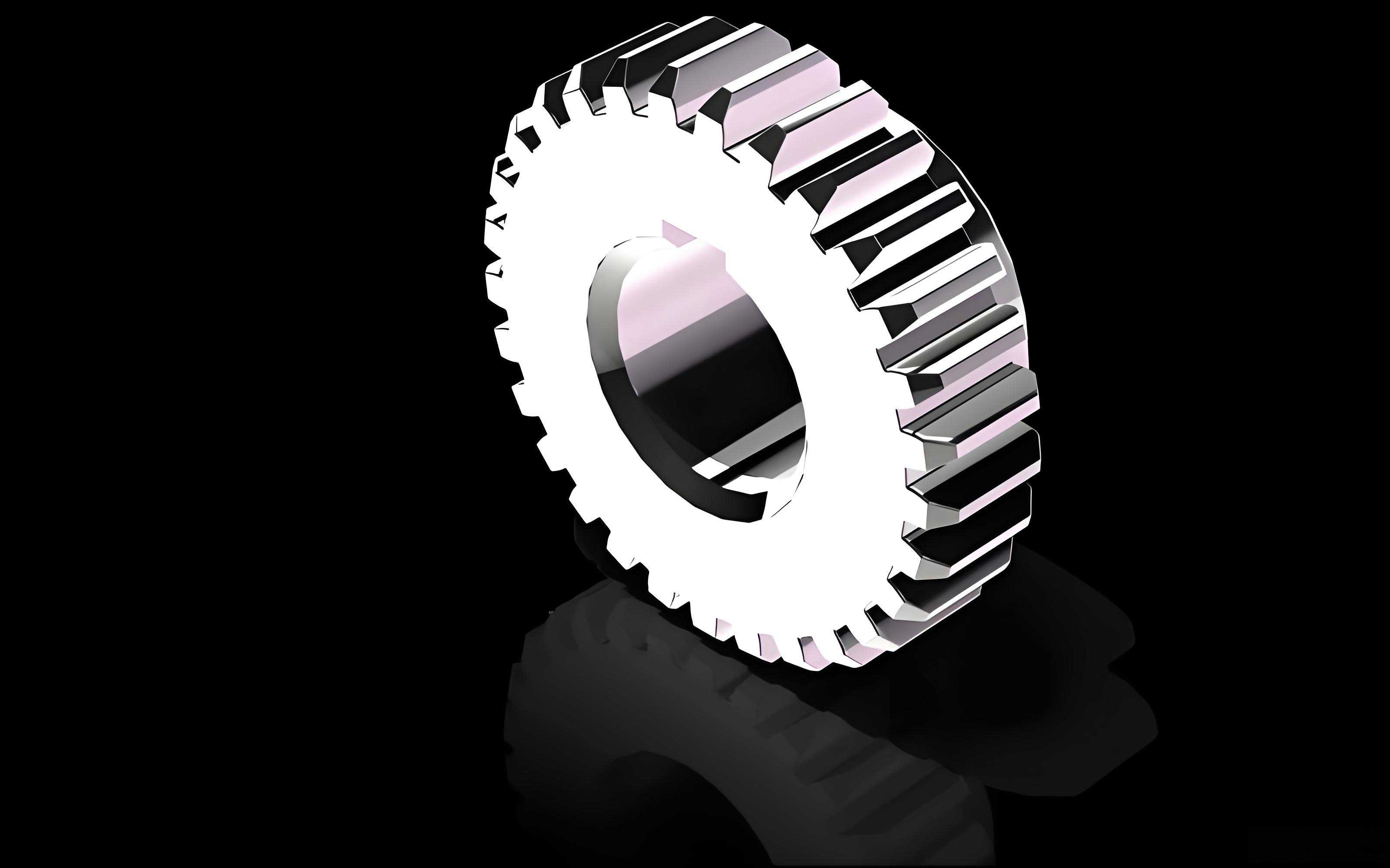
The meshing process of involute spur gears involves alternating between single and double tooth contact zones along the line of action. For spur gears with a contact ratio greater than one, there are regions where two pairs of teeth share the load. This alternating contact leads to complex load variations, which must be modeled accurately. We start by analyzing the meshing state of standard involute spur gears. The theoretical line of action is the common tangent to the base circles, and the actual line of action is determined by the addendum circles. In double tooth contact, two pairs of teeth are engaged simultaneously, while in single tooth contact, only one pair carries the load. This alternation is key to understanding the load distribution in spur gears.
To model the load distribution, we establish a basic mechanical model for spur gears. Consider a spur gear pair where the driving gear transmits torque. During double tooth contact, two points on the line of action experience normal forces, denoted as \( F_1 \) and \( F_2 \). The torque equilibrium equation is given by:
$$ (F_1 + F_2) \cdot r_{b1} = T $$
where \( r_{b1} \) is the base radius of the driving spur gear, and \( T \) is the transmitted torque. The forces \( F_1 \) and \( F_2 \) vary along the meshing cycle, and our goal is to determine their precise values at each position. Under these forces, both gears undergo elastic deformations, including bending deflections of the teeth and Hertzian contact deformations at the contact points. The total deformation at each contact point is the sum of bending deflection and contact deformation.
Let \( \Delta_{\text{gear1-tooth1}} \) represent the total deformation at the first contact point on the driving spur gear, and similarly for other contact points. The deformation compatibility condition states that the normal distances between contact points after deformation must be equal. Initially, the normal distance between two consecutive contact points on the line of action is the base pitch \( p_b \), given by:
$$ p_b = \pi m \cos \alpha $$
where \( m \) is the module and \( \alpha \) is the pressure angle. After deformation, the distances change due to elastic effects. By applying deformation compatibility, we derive the following equation:
$$ \Delta_{\text{gear1-tooth1}} + \Delta_{\text{gear2-tooth1}} = \Delta_{\text{gear1-tooth2}} + \Delta_{\text{gear2-tooth2}} $$
This equation, combined with the torque equilibrium, forms the fundamental mechanical model for spur gears. To solve it, we need expressions for the deformations. The deformation at each contact point consists of bending deflection \( \Delta_c \) and contact deformation \( \Delta_d \). Thus, for example:
$$ \Delta_{\text{gear1-tooth1}} = \Delta_{c,\text{gear1-tooth1}} + \Delta_{d,\text{gear1-tooth1}} $$
We now analyze the bending deflection of spur gear teeth. The tooth profile of an involute spur gear consists of three segments: the tip circle arc, the involute curve, and the root fillet curve. For accuracy, we use exact equations based on gear generation with a standard rack cutter. The coordinate transformations yield the parametric equations for the root fillet and involute profile. In a coordinate system attached to the tooth, the fillet curve equation is derived as:
$$ x_c = – (t – r_d U_2) \sin(U_2 – \nu) + \left[ r_d + (r_c \sin \alpha – h) – \sqrt{r_c^2 – t^2} \right] \cos(U_2 – \nu) – k $$
$$ y_c = – (t – r_d U_2) \cos(U_2 – \nu) – \left[ r_d + (r_c \sin \alpha – h) – \sqrt{r_c^2 – t^2} \right] \sin(U_2 – \nu) $$
$$ U_2 = \frac{(r_c \sin \alpha – h) t}{r_d \sqrt{r_c^2 – t^2}} $$
where \( t \) is a parameter, \( r_c \) is the cutter tip radius, \( r_d \) is the pitch radius, \( \alpha \) is the pressure angle, and \( h \), \( \nu \), \( k \) are geometric constants. The involute profile equation is:
$$ x_c = (-t + r_d U_2) \sin(U_2 – \nu) + \left[ r_d + \cot \alpha (t – r_c \cos \alpha) – h \right] \cos(U_2 – \nu) – k $$
$$ y_c = (-t + r_d U_2) \cos(U_2 – \nu) – \left[ r_d + \cot \alpha (t – r_c \cos \alpha) – h \right] \sin(U_2 – \nu) $$
$$ U_2 = \frac{[(1 + \cot^2 \alpha) t – (\cot \alpha \cos \alpha \cdot r_c + h) \cot \alpha]}{r_d} $$
These equations allow us to determine the exact geometry of the spur gear tooth at any point. To calculate bending deflection, we model the tooth as a variable-section cantilever beam. The deflection curve is governed by the beam equation. For small deflections, the approximate differential equation is:
$$ \frac{d^2 w}{dx^2} = \frac{M}{EI} $$
where \( M \) is the bending moment, \( E \) is Young’s modulus, and \( I \) is the area moment of inertia. For a tooth with load applied at a point along the profile, the moment is \( M = F \cos \alpha_i \cdot (l – x) \), where \( \alpha_i \) is the pressure angle at the load point, \( l \) is the distance from the root to the load point, and \( x \) is the coordinate along the tooth axis. The inertia \( I \) varies with tooth thickness. Integrating this equation yields the bending deflection \( \Delta_c \). For example, for a tooth on the driving spur gear under force \( F_1 \):
$$ \Delta_{c,\text{gear1-tooth1}} = \int \frac{F_1 \cos \alpha_{i1} (l_1 – x)^2}{2E b y^3 / 3} dx + C x + D $$
where \( b \) is the face width, \( y \) is the half-tooth thickness, and \( C \), \( D \) are integration constants determined from boundary conditions. Similar expressions are derived for other teeth.
Next, we consider the Hertzian contact deformation in spur gears. When two teeth contact, they can be approximated as cylinders with radii equal to the radii of curvature at the contact point. The contact deformation \( \Delta_d \) is the sum of the deformations of both cylinders. The semi-width of the contact area \( b \) is given by Hertz formula:
$$ b = \sqrt{ \frac{4F}{\pi L} \cdot \frac{(1 – \nu_1^2)/E_1 + (1 – \nu_2^2)/E_2}{1/R_1 + 1/R_2} } $$
where \( L \) is the face width, \( \nu_1 \), \( \nu_2 \) are Poisson’s ratios, \( E_1 \), \( E_2 \) are Young’s moduli, and \( R_1 \), \( R_2 \) are the radii of curvature at the contact point for the two spur gears. The radial contact deformation for each cylinder is:
$$ \Delta_{d1} = R_1 – \sqrt{R_1^2 – b^2} $$
$$ \Delta_{d2} = R_2 – \sqrt{R_2^2 – b^2} $$
Thus, the total contact deformation at a contact point is \( \Delta_d = \Delta_{d1} + \Delta_{d2} \). For double tooth contact, we have two contact points, so we compute \( \Delta_{d1} \) and \( \Delta_{d2} \) for each pair.
Substituting the expressions for bending and contact deformations into the deformation compatibility equation, we obtain a system of equations in \( F_1 \) and \( F_2 \). Solving this system along with the torque equation yields the load distribution along the meshing cycle. This method allows us to calculate the precise forces on spur gear teeth at any meshing position.
To demonstrate the application of our method, we present a computational example. Consider a spur gear pair from an industrial extruder gearbox. The parameters are summarized in the table below.
| Parameter | Driving Spur Gear | Driven Spur Gear |
|---|---|---|
| Number of Teeth | 23 | 24 |
| Module (mm) | 14 | 14 |
| Pressure Angle (°) | 20 | 20 |
| Face Width (mm) | 500 | 500 |
| Pitch Diameter (mm) | 322 | 336 |
| Base Circle Diameter (mm) | 302.5 | 315.6 |
| Contact Ratio | 1.662 | 1.662 |
| Material | Low Carbon Steel | Low Carbon Steel |
| Young’s Modulus (GPa) | 210 | 210 |
| Poisson’s Ratio | 0.3 | 0.3 |
| Transmitted Power (kW) | 7260 | – |
| Speed (rpm) | 1500 | – |
The torque on the driving spur gear is calculated as:
$$ T = \frac{P}{\omega} = \frac{7260 \times 10^3}{2\pi \times 1500 / 60} \approx 46300 \, \text{Nm} $$
Using our method, we compute the load distribution along the meshing cycle for the driving spur gear. The results are shown in the following table for key positions.
| Meshing Position (x_c in mm) | Load F1 (N) | Load F2 (N) | Contact State |
|---|---|---|---|
| 0.0 | 120000 | 80000 | Double Tooth |
| 20.0 | 140000 | 60000 | Double Tooth |
| 51.8844 | 200000 | 0 | Single Tooth |
| 80.0 | 180000 | 0 | Single Tooth |
| 101.6548 | 100000 | 100000 | Double Tooth |
| 120.0 | 90000 | 110000 | Double Tooth |
The load variation shows sudden changes at the transitions between double and single tooth contact, as expected for spur gears. At \( x_c = 51.8844 \, \text{mm} \), the load spikes as the gear enters single tooth contact, and at \( x_c = 101.6548 \, \text{mm} \), it drops as it re-enters double tooth contact. This pattern is critical for stress analysis in spur gears.
Based on the load distribution, we calculate the contact stress using Hertz theory. The maximum contact stress at any point is given by:
$$ \sigma_H = \sqrt{ \frac{F (1/R_1 + 1/R_2)}{\pi L \left[ (1 – \nu_1^2)/E_1 + (1 – \nu_2^2)/E_2 \right]} } $$
For the driving spur gear, the contact stress distribution is computed. The results indicate that the maximum contact stress occurs at \( x_c = 51.8844 \, \text{mm} \), with a value of approximately 832 MPa. This high stress corresponds to the single tooth contact region, where the full load is carried by one tooth pair. The variation of contact stress along the meshing cycle is summarized below.
| Position Range (x_c in mm) | Average Contact Stress (MPa) | Peak Contact Stress (MPa) |
|---|---|---|
| 0 – 51.8844 (Double Tooth) | 600 | 700 |
| 51.8844 – 101.6548 (Single Tooth) | 800 | 832 |
| 101.6548 – 120 (Double Tooth) | 620 | 650 |
Similarly, we calculate the bending stress at the tooth root of the spur gear. The bending stress is primarily due to the tangential component of the load. For a tooth with root thickness \( S_F \) and distance \( l \) from the load point to the root, the bending stress is:
$$ \sigma_X = \frac{F_t l}{L S_F^2 / 6} $$
where \( F_t = F \cos \alpha_i \) is the tangential force. By evaluating this for different root sections, we find the critical root section where the bending stress is maximum. For our spur gear example, the maximum bending stress occurs at a root thickness of \( S_F = 26.9147 \, \text{mm} \), with a value of about 772 MPa. The bending stress distribution over the meshing cycle is shown in the following table.
| Meshing Phase | Maximum Bending Stress (MPa) | Location (x_c in mm) |
|---|---|---|
| Initial Double Tooth | 500 | 10.0 |
| Single Tooth | 750 | 70.0 |
| Final Double Tooth | 772 | 101.6548 |
The results highlight that the maximum bending stress in spur gears often occurs at the transition from single to double tooth contact, where the bending moment is highest due to load sharing changes.
Our method provides a robust framework for analyzing spur gear mechanics. By incorporating exact tooth geometry and deformation compatibility, we achieve accurate load and stress calculations. The key advantages include the ability to handle alternating contact conditions, precise deformation modeling, and elimination of simplifications common in prior works. This approach is particularly useful for designing high-performance spur gears in applications such as automotive transmissions, industrial machinery, and aerospace systems.
In discussion, we note that the load distribution in spur gears is highly sensitive to geometric parameters like pressure angle, module, and tooth numbers. For instance, increasing the contact ratio can smooth load transitions but may alter stress concentrations. Our model can be extended to include dynamic effects, misalignments, and profile modifications for further realism. Additionally, the use of advanced materials for spur gears, such as composites or high-strength alloys, can be studied by adjusting material properties in the deformation equations.
In conclusion, we have developed a comprehensive method for calculating load and stress in involute spur gears. This method integrates mechanical modeling, deformation analysis, and exact geometry to provide precise results. Through a detailed example, we demonstrated the calculation of load distribution, contact stress, and bending stress for a spur gear pair. The findings emphasize the importance of considering deformation compatibility and alternating contact in spur gear design. Future work may involve experimental validation, extension to helical gears, and incorporation of thermal effects. Our contribution offers a valuable tool for engineers and researchers working on spur gear systems.