
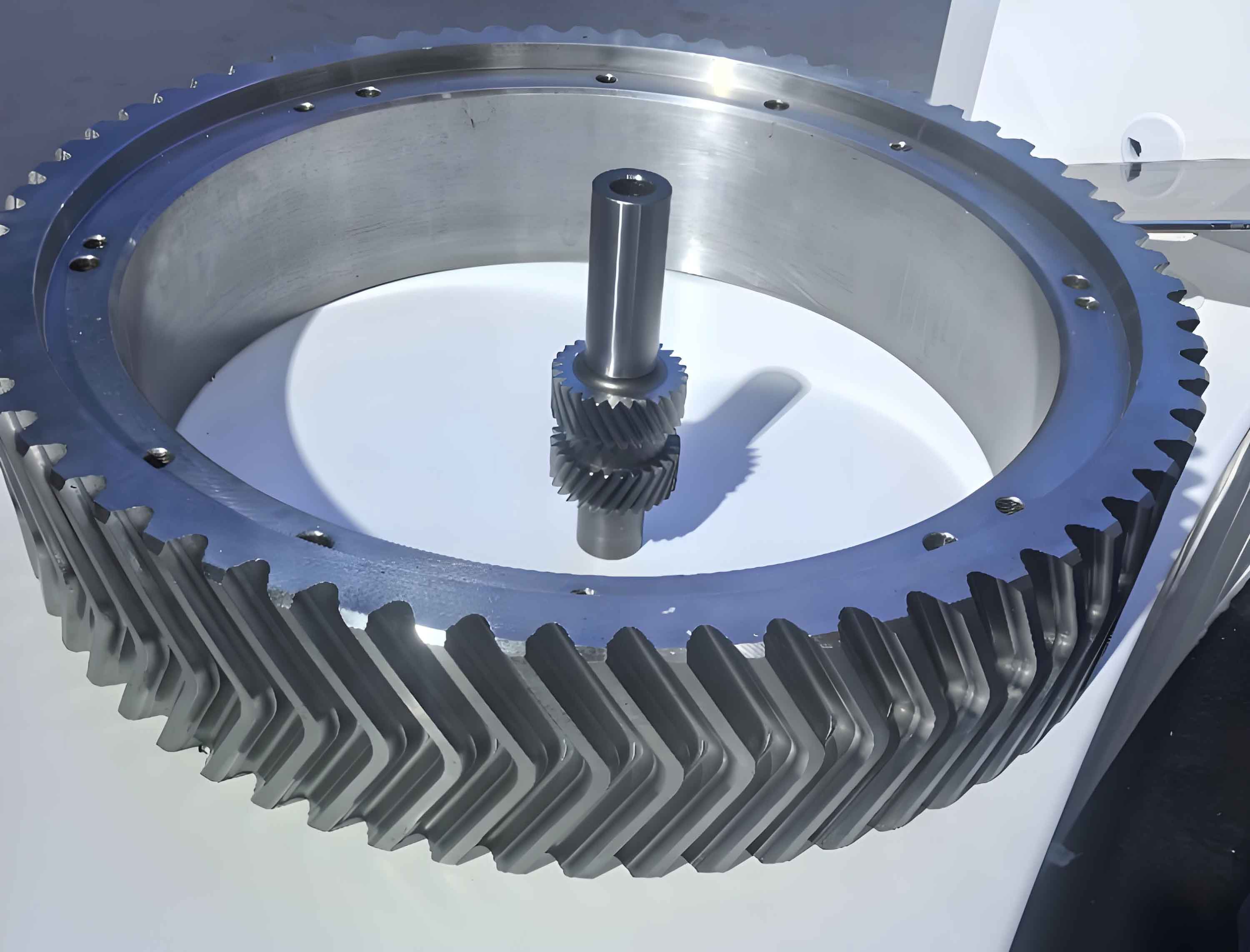
In the realm of high-power, high-torque transmission systems, herringbone gears are indispensable components. Their unique double-helical geometry offers significant advantages, most notably the inherent cancellation of axial thrust forces generated by individual helical teeth. This leads to quieter operation, reduced bearing loads, and the ability to transmit substantial power in a compact form factor. Consequently, herringbone gears are the preferred choice in demanding applications such as marine propulsion systems, heavy-duty industrial gearboxes, aerospace power units, and wind turbine drivetrains. The figure below illustrates the characteristic V-shaped teeth of a herringbone gear.
However, the theoretical perfection of herringbone gears, where loads are perfectly balanced between the left and right flanks, is challenging to achieve in practice. A critical and often unavoidable manufacturing imperfection is bilateral tooth misalignment. This error arises during the machining process due to factors like machine tool deflection, fixture inconsistencies, thermal effects, or cutter wear. It results in a scenario where the teeth on one side of the herringbone gear engage slightly earlier or later than the teeth on the opposite side relative to the mating gear. This temporal offset, often quantified as a phase error or “stagger angle,” disrupts the intended simultaneous load sharing. The immediate consequence is a pronounced stress bias load, where one flank carries a disproportionately larger share of the transmitted torque. In severe cases, this can degenerate into single-flank contact, effectively nullifying one of the primary benefits of the herringbone design. This uneven loading accelerates fatigue-driven failure mechanisms such as pitting on the contact surfaces and bending fatigue at the tooth root on the overloaded side, leading to premature gearbox failure, unplanned downtime, and significant economic costs.
This article presents a comprehensive investigation into the phenomenon of stress bias load in herringbone gears induced by misalignment error. The objective is threefold: first, to establish a clear theoretical relationship between misalignment error, system parameters, and the resulting load imbalance; second, to validate this relationship through detailed finite element analysis (FEA); and third, to synthesize practical design and operational guidelines for mitigating this detrimental effect. By understanding the interplay between manufacturing errors, system stiffness, and operational loads, engineers can make informed decisions to enhance the reliability and performance of herringbone gear systems.
Theoretical Modeling of Stress Bias Load
The core of the problem lies in quantifying the load disparity. We begin by defining a key metric: the Stress Bias Load Coefficient, denoted as $D_l$. This coefficient provides a normalized measure of the load imbalance between the two flanks of the herringbone gear.
$$D_l = 2 \left| \frac{F_1 – F_2}{F_1 + F_2} \right| = 2 \left| \frac{\sigma_1 – \sigma_2}{\sigma_1 + \sigma_2} \right|$$
Here, $F_1$ and $F_2$ represent the meshing forces on the left and right flanks, respectively, while $\sigma_1$ and $\sigma_2$ are the corresponding root bending stresses, which are directly proportional to the meshing forces. The coefficient $D_l$ ranges from 0 to 2. A value of $D_l = 0$ indicates perfect load sharing. A value of $D_l = 2$ signifies the worst-case scenario of single-flank contact, where one flank carries the entire load and the other carries none. Any value between 0 and 2 indicates a partial bias load.
To model the misalignment, we consider the left flank of the driving herringbone gear as the reference. The right flank is considered to have a misalignment error $\delta$, defined as a small rotational offset about the gear axis. By convention, a positive $\delta$ indicates the right flank is phase-advanced (leads) relative to the left flank. The engagement process can be conceptually divided into four distinct stages as the gears rotate:
- Stage 1 (No Contact): Both flanks are out of contact, separated by initial backlash $B_{L1}$ and $B_{R1}$.
- Stage 2 (Single-Flank Contact – Lead Side): The flank with the phase advance (e.g., right flank if $\delta > 0$) comes into contact first. Its deformation is zero at the initial contact point, while the other flank still has a residual backlash $B_{L2}$.
- Stage 3 (Transition to Dual Contact): As loading increases, the leading flank deforms by an amount $l_{n1}$. The trailing flank just makes contact, with zero deformation.
- Stage 4 (Dual-Flank Contact): Both flanks are engaged and sharing the load. The leading flank has a total deformation of $l_{n1} + l_{n2}$, and the trailing flank has a deformation of $l_{n2}$, where $l_{n2}$ is the additional deformation under the shared load state.
The normal deformation $l_n$ of a gear tooth pair under load is related to the static transmission error $\Delta \theta$ by the gear geometry:
$$l_n = \Delta \theta \cdot \frac{m_n z_2 \cos \alpha_t}{2 \cos \beta \cos \beta_b}$$
where $m_n$ is the normal module, $z_2$ is the number of teeth on the driven gear, $\alpha_t$ is the transverse pressure angle, $\beta$ is the helix angle, and $\beta_b$ is the base helix angle.
The misalignment error $\delta$ translates directly into an initial normal deformation difference $l_{n1}$ between the flanks at the onset of dual contact (Stage 3):
$$l_{n1} = \delta \cdot \frac{m_n z_2 \cos \alpha_t}{2 \cos \beta \cos \beta_b}$$
The total transmitted force $F_z$ is related to the input torque $T$:
$$F_z = F_1 + F_2 = \frac{2000 \cdot T}{m_n z_2 \cos \alpha_t}$$
Assuming a linearized meshing stiffness $K_m$ (the combined stiffness of the tooth pair and supporting structure in the direction of the line of action), the force on a flank is proportional to its deformation: $F = K_m \cdot l_n$. During dual-flank contact, the force difference is $F_1 – F_2 = K_m \cdot l_{n1}$. Substituting into the definition of $D_l$ and using the expressions above, we arrive at the fundamental theoretical relationship:
$$D_l = \frac{|F_1 – F_2|}{F_z / 2} = \frac{K_m \cdot l_{n1}}{F_z / 2} = \frac{(m_n z_2 \cos \alpha_t)^2}{4000 \cos \beta \cos \beta_b} \cdot \frac{K_m \cdot \delta}{T}$$
For a given herringbone gear pair, the geometric term $\frac{(m_n z_2 \cos \alpha_t)^2}{4000 \cos \beta \cos \beta_b}$ is a constant. Therefore, the theoretical model reveals three critical, actionable insights:
$$D_l \propto \frac{K_m \cdot \delta}{T}$$
- Proportional to Misalignment Error ($\delta$): Increasing the manufacturing precision to reduce $\delta$ directly reduces the stress bias load.
- Proportional to Meshing Stiffness ($K_m$): A stiffer gear system (e.g., wider teeth, higher modulus material) is more sensitive to misalignment, exacerbating the load imbalance.
- Inversely Proportional to Torque ($T$): Counterintuitively, operating the gearbox at higher loads (within design limits) can improve load sharing between the flanks.
This simple yet powerful relationship forms the basis for our subsequent analysis. The following sections will use detailed finite element simulations to validate this proportionality and explore additional factors, such as axial support flexibility, not explicitly captured in the initial linear model.
Finite Element Analysis and Validation
To verify the theoretical conclusions and investigate non-linear effects, a three-dimensional finite element model of a herringbone gear pair was developed. The model focuses on a segment containing five teeth from both the driving and driven gears to balance computational accuracy and efficiency. The core parameters of the gear pair are summarized in Table 1.
| Parameter | Driving Gear | Driven Gear |
|---|---|---|
| Normal Module, $m_n$ (mm) | 4 | 4 |
| Number of Teeth, $z$ | 34 | 31 |
| Helix Angle, $\beta$ (deg) | 30 | 30 |
| Normal Pressure Angle, $\alpha_n$ (deg) | 22.5 | 22.5 |
| Face Width per Flank (mm) | 48 | 48 |
| Material Density (kg/m³) | 7850 | 7850 |
| Young’s Modulus, $E$ (GPa) | 210 (Baseline) | 210 (Baseline) |
| Poisson’s Ratio, $\nu$ | 0.3 | 0.3 |
The simulation process involved two main steps: first, a small rotational displacement was applied to eliminate initial backlash and establish contact; second, a static torque was applied to the driving gear while the driven gear was fully constrained at its center. This process was repeated at multiple angular positions to simulate the meshing cycle of a central tooth pair. The primary output metrics were the maximum tensile and compressive root bending stresses on both the left and right flanks of the driving gear, from which the Stress Bias Load Coefficient $D_l$ was calculated.
Effect of Misalignment Error ($\delta$)
A series of simulations were conducted with misalignment errors ranging from 0° to 0.02°. The results, plotted as stress and $D_l$ versus $\delta$, confirmed the linear relationship predicted by theory for a significant range. At $\delta = 0°$, $D_l = 0$, indicating perfect balance. As $\delta$ increased, the stress on the leading flank increased while the stress on the trailing flank decreased, causing $D_l$ to rise linearly. Beyond a critical threshold (approximately $\delta = 0.015°$ in this model), the trailing flank disengaged completely, resulting in single-flank contact and $D_l = 2$. The contact pressure distribution visually shifted from being evenly distributed across both flanks at $\delta=0°$ to being concentrated solely on the leading flank at high $\delta$. The maximum contact pressure also increased significantly with $\delta$, highlighting the dual detriment of bias load and elevated localized stress.
| Misalignment Error $\delta$ | Load State | Stress Bias Load Coefficient $D_l$ | Trend in Max Contact Stress |
|---|---|---|---|
| 0° | Perfect Dual-Flank Contact | 0 | Baseline, Even Distribution |
| 0° < $\delta$ < $\delta_{critical}$ | Biased Dual-Flank Contact | Linear Increase with $\delta$ | Increases, Uneven Distribution |
| $\delta$ ≥ $\delta_{critical}$ | Single-Flank Contact | 2 | Significantly Higher, Single Flank Only |
Effect of Input Torque ($T$)
Simulations with a fixed misalignment error ($\delta = 0.01°$) and varying input torque provided clear validation of the inverse relationship with $D_l$. At very low torque (≤ 500 N·m), the system remained in single-flank contact ($D_l=2$). As torque increased beyond this threshold, the trailing flank engaged, initiating dual-flank contact. Crucially, with further increases in torque, the absolute difference in stress between the two flanks remained relatively constant, but because the total load $F_z$ increased, the normalized coefficient $D_l$ decreased. This demonstrates that operating herringbone gears closer to their design capacity can be beneficial for load sharing, as the increased deformation helps to “soak up” the initial misalignment error. The contact patterns evolved from a single contact patch at low torque to two increasingly similar patches at high torque.
$$D_l(T) \approx \frac{C}{T} \quad \text{(for } T > T_{threshold} \text{)}$$
where $C$ is a constant for a given $\delta$ and $K_m$.
Effect of Meshing Stiffness via Young’s Modulus ($E$)
The meshing stiffness $K_m$ is a complex function of tooth geometry, material properties, and foundation stiffness. A direct proxy for material contribution is Young’s Modulus $E$. Simulations where $E$ was varied from 100 GPa to 300 GPa, with constant $\delta$ and $T$, confirmed the theoretical proportionality $D_l \propto K_m$. As $E$ increased, making the teeth stiffer, the difference in root stress between the two flanks grew larger, and $D_l$ increased linearly. A more compliant material (lower $E$) allows for greater elastic compensation of the misalignment, leading to better load sharing. This is a critical design trade-off: while high-stiffness materials are often chosen for strength, they can worsen the system’s sensitivity to manufacturing errors in herringbone gears.
| Parameter | Theoretical Relationship | FEA Observation | Practical Implication |
|---|---|---|---|
| Misalignment Error ($\delta$) ↑ | $D_l \propto \delta$ | Linear increase in $D_l$, up to single-flank contact. | Stringent manufacturing control is paramount. |
| Input Torque ($T$) ↑ | $D_l \propto 1/T$ | $D_l$ decreases with increasing torque after dual contact is established. | Operating at higher load factors can improve balance. |
| Meshing Stiffness ($K_m$) ↑ | $D_l \propto K_m$ | Increasing material $E$ (stiffness) leads to linear increase in $D_l$. | Softer materials or flexible tooth designs can mitigate bias. |
| Axial Support Stiffness ($k_{ZZ}$) ↓ | Not in basic model | Significant reduction in $D_l$ with decreased $k_{ZZ}$. | Axial “float” or flexible mounts are highly effective. |
Effect of Axial Support Flexibility ($k_{ZZ}$)
An important factor not explicitly included in the simple linear model is the axial support stiffness of the gear shafts, represented by the bearing stiffness coefficient $k_{ZZ}$ in the axial direction. In practice, herringbone gears are often mounted with some degree of axial flexibility or “float” to promote self-alignment. FEA simulations were conducted where the axial stiffness at the bearing locations was systematically varied over several orders of magnitude, from a very rigid support ($10^{12}$ N/m) to a very compliant one ($10^6$ N/m).
The results were striking. For high axial stiffness, the $D_l$ value was high, consistent with previous results. As $k_{ZZ}$ was reduced, the $D_l$ value dropped significantly. At the most compliant setting ($k_{ZZ}=10^6$ N/m), the load sharing was vastly improved. The physical mechanism is one of self-compensation: under load, the axial force component from the leading flank pushes the gear axially, allowing the trailing flank to engage more fully. This axial displacement, $\Delta Z$, is inversely proportional to the axial support stiffness. The improved load distribution was visually confirmed by more symmetrical contact patterns on the two flanks. This highlights a powerful and practical mitigation strategy: designing the system with intentional axial compliance, either through specific bearing arrangements or flexible coupling elements, can dramatically reduce sensitivity to misalignment error in herringbone gears.
The relationship can be conceptually expressed as:
$$D_l(k_{ZZ}) \approx D_l^{rigid} \cdot f(k_{ZZ})$$
where $f(k_{ZZ})$ is a decreasing function of $k_{ZZ}$, and $D_l^{rigid}$ is the bias coefficient for a perfectly rigid axial support.
Design Guidelines and Mitigation Strategies
Based on the integrated theoretical and numerical analysis, a set of coherent guidelines can be formulated for the design and application of herringbone gears to manage stress bias load. These strategies operate on the fundamental principle of reducing the system’s sensitivity to the unavoidable misalignment error $\delta$, as encapsulated by the derived relationship $D_l \propto (K_m \cdot \delta) / T$ and augmented by the finding on axial flexibility.
- Primary Strategy: Minimize the Source Error ($\delta$)
- Invest in high-precision manufacturing processes (e.g., grinding) and stringent quality control for the gear cutting and heat treatment stages.
- Implement accurate and robust fixturing systems to minimize setup errors during machining.
- Consider post-manufacturing inspection and selective assembly to match gear pairs with complementary error profiles.
- Secondary Strategy: Reduce System Sensitivity ($K_m$)
- Material Selection: While high-strength steels are common, their high Young’s Modulus increases $K_m$. For highly sensitive applications, the benefits of a lower-modulus, high-strength material (e.g., certain titanium alloys) for improved load sharing should be evaluated against other design constraints.
- Tooth Design: Incorporating slight crown or lead modifications can create a more compliant contact zone, effectively reducing the local mesh stiffness and allowing for better conformity under misalignment.
- Support Structure: Designing the gear blanks with more flexible webs or rims can lower the overall foundation stiffness component of $K_m$, promoting load sharing.
- Tertiary Strategy: Exploit Operational and Design Flexibility
- Torque Management: Design systems to operate consistently at higher load factors where feasible. Avoid prolonged operation at very low-torque conditions, as this is when bias load is most severe and can lead to wear-in on only one flank.
- Axial Flexibility (Crucial Finding): Deliberately introduce controlled axial compliance into the gear shaft support system. This can be achieved through:
- Using cylindrical roller bearings which permit axial slip.
- Employing a “floating” design for one of the herringbone gears in the pair.
- Incorporating axially flexible couplings or diaphragms in the shaft line.
This allows the gear pair to self-center under load, providing a powerful mechanical compensation for misalignment error that is often more practical than achieving perfect machining.
The effectiveness of these strategies can be ranked and combined, as summarized in Table 4.
| Strategy Category | Specific Action | Mechanism | Relative Effectiveness / Cost | Comment |
|---|---|---|---|---|
| Error Source Control | High-Precision Machining | Directly reduces $\delta$. | High Effectiveness, High Cost | Fundamental but subject to diminishing returns. |
| Precision Fixturing & Inspection | Reduces $\delta$ and allows error matching. | Medium-High Effectiveness, Medium Cost | Essential part of quality process. | |
| System Desensitization | Introduce Axial Flexibility ($k_{ZZ}↓$) | Enables self-alignment and load compensation. | Very High Effectiveness, Low-Medium Cost | One of the most practical and powerful measures. |
| Operate at Higher Torque ($T↑$) | Exploits inverse relationship $D_l \propto 1/T$. | High Effectiveness, No Direct Cost | Contingent on operational profile and design limits. | |
| Optimize Material/Tooth Stiffness ($K_m↓$) | Reduces proportionality constant in $D_l$ equation. | Medium Effectiveness, Variable Cost | Involves trade-offs with strength and durability. |
Conclusion
This analysis provides a comprehensive framework for understanding and addressing the critical issue of stress bias load in herringbone gears arising from manufacturing misalignment. The established theoretical model, $D_l \propto (K_m \cdot \delta) / T$, successfully captures the core relationships, identifying misalignment error and meshing stiffness as exacerbating factors and input torque as a mitigating factor. Extensive finite element simulations have validated these relationships and revealed the profound mitigating influence of axial support flexibility, a key practical insight not initially contained in the simple model.
The load imbalance in herringbone gears is not merely a function of manufacturing quality but a system-level property determined by the interaction of error, stiffness, load, and boundary conditions. Therefore, the path to reliable herringbone gear performance lies in a systems engineering approach. While striving for minimal misalignment through precision manufacturing remains the first line of defense, it is often economically and technically bounded. A more robust and frequently more economical solution involves designing the system to be tolerant of these inevitable errors. Specifically, incorporating intentional axial flexibility and ensuring operation within an adequate load range are highly effective strategies to promote load sharing and ensure the longevity of herringbone gear transmissions. Future research could fruitfully extend this work to more complex configurations, such as planetary or star gear systems employing herringbone gears, where the interactions between multiple gear meshes and floating components would further elaborate the dynamics of load sharing in the presence of combined errors.