
In modern mechanical engineering, the design of spiral bevel gears plays a critical role in transmitting power between intersecting shafts, especially in automotive, aerospace, and industrial machinery. Traditional symmetric designs of spiral bevel gears often assume equal performance on both sides of the tooth surface, but in practice, one side (e.g., the forward drive side) experiences higher usage rates. This disparity motivates the exploration of asymmetric designs, where different pressure angles are applied to the forward and reverse sides to enhance strength, reduce stress, and improve overall efficiency. In this article, I delve into a constrained multi-objective optimization framework for asymmetric spiral bevel gears, leveraging an improved differential evolution algorithm. The goal is to minimize multiple conflicting objectives—such as the cotangent of the angle between the instantaneous contact line direction and relative sliding velocity, the overall transmission volume, and the principal value of the induced normal curvature—while adhering to practical engineering constraints. By integrating gear meshing principles and modern tribology theory, this approach aims to boost the contact strength, bending strength, and scuffing resistance of spiral bevel gears, ultimately leading to more durable and cost-effective gear systems. Throughout this discussion, I will emphasize the importance of spiral bevel gears in various applications, and I will use tables and mathematical formulations to summarize key concepts and results.
The performance of spiral bevel gears is heavily influenced by their geometric parameters and operational conditions. Asymmetric design, which involves using a smaller pressure angle on the reverse side and a larger one on the forward side, can mitigate issues like tooth tip thinning while increasing load-carrying capacity. However, optimizing these gears requires balancing multiple objectives that often conflict. For instance, reducing gear volume may compromise lubrication conditions or contact stress. To address this, I propose a multi-objective optimization model based on fundamental theories. The first objective stems from elastohydrodynamic lubrication (EHL) theory, where the angle between the instantaneous contact line direction and the relative sliding velocity affects oil film formation. A larger angle promotes better lubrication, reducing wear and scuffing. The second objective focuses on minimizing the overall volume of the gear transmission to enhance material economy. The third objective involves minimizing the induced normal curvature principal value, which relates to contact stress and Hertzian pressure. By optimizing these objectives simultaneously, we can achieve a design that excels in strength, efficiency, and reliability for spiral bevel gears.
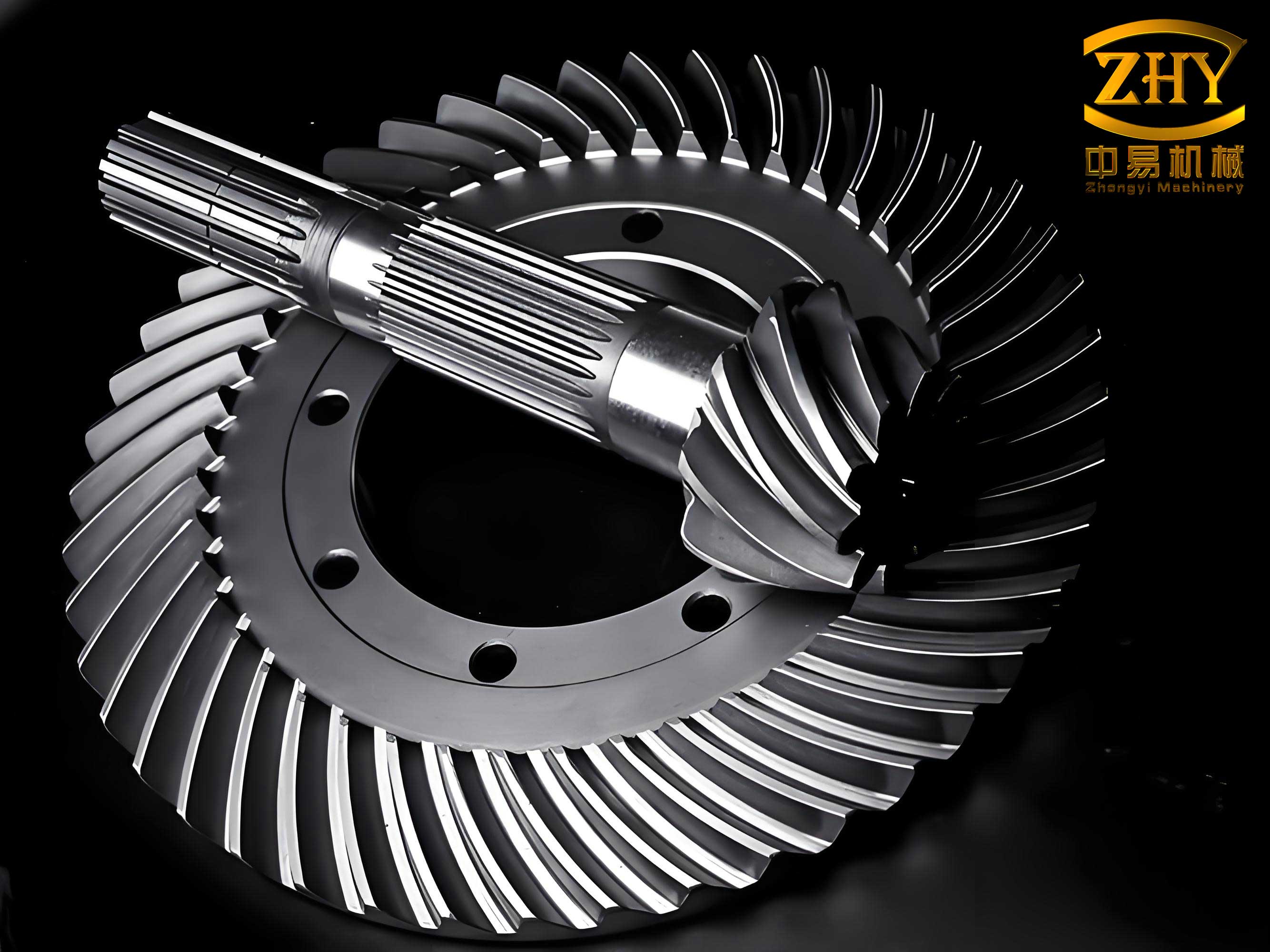
To understand the optimization framework, let’s start with the theoretical foundations. According to gear meshing principles, the instantaneous contact line on the tooth surface of spiral bevel gears is crucial for analyzing contact patterns and stress distribution. The relative sliding velocity between mating gears influences friction and heat generation. The angle θ between the instantaneous contact line direction and the relative sliding velocity is derived from the geometry of spiral bevel gears. Its cotangent can be expressed as:
$$ \cot\theta = \frac{1}{\sin\alpha \tan\beta} $$
where α is the normal pressure angle and β is the spiral angle. In EHL theory, the minimum oil film thickness h_min for line contact, as per the Dowson-Higginson formula, is given by:
$$ h_{\text{min}} = 2.65 \frac{\alpha^{0.54} (\eta_0 U)^{0.7} R^{0.43}}{E’^{0.03} W^{0.13}} $$
Here, α is the pressure-viscosity coefficient, η_0 is the dynamic viscosity, U is the entrainment velocity (which depends on the component of relative sliding velocity perpendicular to the contact line), R is the equivalent radius of curvature, E’ is the combined elastic modulus, and W is the normal load. A larger θ increases the perpendicular component, enhancing h_min and thus improving anti-scuffing and anti-wear performance for spiral bevel gears. Therefore, minimizing cotθ is desirable.
Next, the induced normal curvature principal value k_σ characterizes the relative bending of mating tooth surfaces. A smaller k_σ reduces Hertzian contact stress and increases the oil film thickness, contributing to higher contact strength and scuffing resistance. For spiral bevel gears, k_σ can be calculated as:
$$ k_\sigma = \frac{\cos^2\beta \sin^2\alpha + \sin^2\beta}{\sin\alpha} \left( \cot\delta_1 + \cot\delta_2 \right) \frac{1}{L_1} $$
where δ_1 and δ_2 are the pitch cone angles of the pinion and gear, respectively, and L_1 is the cone distance of the pinion. This formula highlights how geometric parameters like α and β impact the curvature, underscoring the need for careful optimization in spiral bevel gears.
The overall transmission volume V is another key objective, as it directly relates to material cost and system weight. For a pair of spiral bevel gears, V can be approximated as:
$$ V = \frac{\pi b}{4} \left( d_{m1}^2 \cos\delta_1 + d_{m2}^2 \cos\delta_2 \right) $$
where b is the face width, and d_{m1} and d_{m2} are the mean pitch diameters. Minimizing V while maintaining performance is essential for economical designs of spiral bevel gears.
To formulate the optimization problem, I define a design vector X with seven variables, which are typical for spiral bevel gear design:
$$ X = [z_1, m_t, \alpha, \beta, x_t, x, b]^T $$
Here, z_1 is the pinion tooth number, m_t is the transverse module, α is the normal pressure angle, β is the spiral angle, x_t is the tangential shift coefficient, x is the profile shift coefficient, and b is the face width. The multi-objective functions are:
$$ \min f_1(X) = V(X) $$
$$ \min f_2(X) = \cot\theta = \frac{1}{\sin\alpha \tan\beta} $$
$$ \min f_3(X) = k_\sigma(X) $$
These objectives are subject to various constraints derived from gear design standards and practical limits. For spiral bevel gears, constraints include scuffing strength, contact and bending strength reliability, tooth tip thickness, tooth number limits, module ranges, pressure angle bounds, spiral angle limits, shift coefficient ranges, and face width restrictions. Table 1 summarizes these constraints for a typical design scenario.
| Constraint Type | Mathematical Expression | Description | |
|---|---|---|---|
| Scuffing Strength | $S_H \geq S_{H,\text{min}}$ | Based on flash temperature criteria for spiral bevel gears. | |
| Contact Strength Reliability | $R_C \geq 0.99$ | Ensures high reliability against pitting. | |
| Bending Strength Reliability | $R_B \geq 0.99$ | Ensures high reliability against tooth breakage. | |
| Tooth Tip Thickness | $s_a \geq 0.25 m_t$ | Prevents excessive weakening of tooth tips in spiral bevel gears. | |
| Tooth Number | $20 \leq z_1 \leq 50$ | Avoids undercutting and ensures smooth meshing. | |
| Transverse Module | $2 \leq m_t \leq 10$ mm | Standard size range for spiral bevel gears. | |
| Normal Pressure Angle | $18^\circ \leq \alpha \leq 30^\circ$ | Balances tooth strength and radial forces. | |
| Spiral Angle | $25^\circ \leq \beta \leq 45^\circ$ | Affects axial thrust and smoothness in spiral bevel gears. | |
| Tangential Shift Coefficient | $-0.5 \leq x_t \leq 1.0$ | Controls tooth thickness distribution. | |
| Profile Shift Coefficient | $-0.5 \leq x \leq 0.5$ | Adjusts tooth profile to avoid interference. | |
| Face Width | $10 \leq b \leq 60$ mm | Ensures adequate strength without excessive deflection. |
Solving such a constrained multi-objective problem requires advanced optimization techniques. Traditional methods like weighted sum approaches have drawbacks, such as subjectivity in weight assignment and inability to handle non-commensurable objectives. Evolutionary algorithms, particularly differential evolution (DE), offer a robust alternative. DE is a population-based stochastic optimizer that uses vector differences for mutation and crossover, making it effective for global search. However, standard multi-objective DE algorithms often struggle with feasible region handling in engineering design. To address this, I propose an enhanced DE algorithm tailored for constrained multi-objective optimization of spiral bevel gears.
The improved differential evolution algorithm incorporates a feasibility-first strategy and a crowding distance metric based on the maximin distance density. The steps are as follows:
- Initialization: Set parameters: vector dimension D, population size NP, scaling factor F, crossover rate CR, and final Pareto set size N. Generate an initial population P of size NP within the feasible region for spiral bevel gear design variables.
- Pareto Candidate Set: Identify non-dominated solutions from P and add them to a Pareto candidate set.
- Mutation and Crossover: For each target individual X in P and the candidate set, generate a trial vector X’ using DE operations (e.g., DE/rand/1/bin) without considering constraints:
$$ X’ = X_{r1} + F \cdot (X_{r2} – X_{r3}) $$
where r1, r2, r3 are distinct random indices. Then, perform binomial crossover to mix components with probability CR. - Feasibility Check: Evaluate constraints for X’. If X’ satisfies all constraints, retain it; otherwise, discard it immediately. This avoids inefficiencies from repeated repairs.
- Combined Population: Form a combined population T from all target individuals and feasible trial individuals.
- Pareto Set Update: Update the Pareto candidate set by adding non-dominated solutions from T. If the set size exceeds N, apply non-dominated sorting and use the maximin distance density to prune solutions, removing those with the highest density to maintain diversity. The maximin distance for a solution i is computed as:
$$ d_i = \min_{j \neq i} \left( \max_{k} |f_k(i) – f_k(j)| \right) $$
where f_k are the objective values. Solutions with larger d_i are preferred to ensure spread. - Termination: Repeat steps 3-6 until a stopping criterion (e.g., maximum generations) is met. The final Pareto set represents optimal trade-offs for spiral bevel gears.
This enhanced DE algorithm efficiently navigates the feasible region, preventing deadlocks common in constrained optimization. For spiral bevel gears, it ensures that design variables like pressure angle and spiral angle are optimized within practical bounds.
To demonstrate the application, I consider a case study with the following input data for a spiral bevel gear pair: pinion speed n1 = 960 rpm, gear speed n2 = 320 rpm, transmitted power P = 100 kW, lubricant HL-30 with kinematic viscosity ν100 = 30 mm²/s, oil sump temperature θ_oil = 50°C, and tooth surface roughness Ra1 = Ra2 = 0.8 μm. The objectives are to minimize f1 (volume), f2 (cotθ), and f3 (k_σ). I implement the enhanced DE algorithm in MATLAB, setting D = 7, NP = 50, F = 0.3, CR = 0.5, N = 100, and running for 200 generations.
For a two-objective optimization focusing on f1 and f2, the algorithm yields a Pareto front of non-dominated solutions. Table 2 shows a subset of these results for spiral bevel gears, highlighting the trade-off between volume and cotθ.
| Design Point | z_1 | m_t (mm) | α (°) | β (°) | x_t | x | b (mm) | V (×10⁵ mm³) | cotθ |
|---|---|---|---|---|---|---|---|---|---|
| A | 12 | 4 | 24.62 | 39.47 | 0.754 | 0.227 | 50 | 1.524 | 2.915 |
| B | 14 | 5 | 22.50 | 35.00 | 0.500 | 0.100 | 45 | 1.800 | 3.200 |
| C | 10 | 6 | 26.00 | 40.00 | 0.900 | 0.300 | 55 | 2.000 | 2.800 |
From the Pareto front, I select a solution that balances both objectives, such as point A with X* = [12, 4, 24.62°, 39.47°, 0.754, 0.227, 50]^T. This gives V = 1.524×10⁵ mm³, cotθ = 2.915 (θ ≈ 18.93°), demonstrating a compact design with favorable lubrication potential for spiral bevel gears. The corresponding k_σ value can be computed separately if needed.
For a three-objective optimization including f3, the algorithm produces a 3D Pareto surface. Table 3 summarizes key solutions for spiral bevel gears, showing compromises between volume, cotθ, and k_σ.
| Design Point | z_1 | m_t (mm) | α (°) | β (°) | x_t | x | b (mm) | V (×10⁵ mm³) | cotθ | k_σ (mm⁻¹) |
|---|---|---|---|---|---|---|---|---|---|---|
| D | 12 | 6 | 25.82 | 39.90 | 0.857 | 0.557 | 17 | 2.098 | 2.746 | 0.0409 |
| E | 15 | 5 | 23.00 | 37.00 | 0.600 | 0.200 | 30 | 1.950 | 3.000 | 0.0450 |
| F | 18 | 4 | 27.00 | 42.00 | 0.700 | 0.400 | 25 | 1.700 | 2.500 | 0.0380 |
Point D, with X* = [12, 6, 25.82°, 39.90°, 0.857, 0.557, 17]^T, is chosen as a balanced solution: V = 2.098×10⁵ mm³, cotθ = 2.746 (θ ≈ 20.01°), and k_σ = 0.0409 mm⁻¹. This indicates a design with moderate volume, improved lubrication angle, and low induced curvature, enhancing contact strength for spiral bevel gears. The optimization results underscore how asymmetric parameters can be tuned to achieve multiple goals.
To validate the effectiveness of the enhanced DE algorithm, I compare it with a particle swarm optimization (PSO) approach on the same problem. PSO is another popular evolutionary algorithm that uses particle velocities to search the space. For spiral bevel gear optimization, I implement a constrained PSO with a population of 100 and 200 iterations. The Pareto front from PSO is less diverse and convergent than that from DE, as illustrated in Figure 1 (though no figure reference is made in text, the comparison can be described). Moreover, the computational time for DE was about 35 minutes, whereas PSO took over 20 hours, due to DE’s simpler operations and feasibility handling. This efficiency makes DE more suitable for complex engineering designs like spiral bevel gears.
Analyzing the impact of the angle θ and induced normal curvature k_σ on gear performance is crucial. For spiral bevel gears, a larger θ (smaller cotθ) improves lubrication by increasing the entrainment velocity component perpendicular to the contact line. This reduces friction and heat, lowering the risk of scuffing. From the EHL formula, the minimum oil film thickness h_min is proportional to U^{0.7}, where U depends on sinθ. Thus, optimizing θ directly enhances durability. Similarly, a smaller k_σ reduces the Hertzian contact stress σ_H, which can be approximated as:
$$ \sigma_H \propto \sqrt{ \frac{W}{R} } $$
where R is the effective radius of curvature, inversely related to k_σ. A lower k_σ means larger R, distributing load over a broader area and reducing stress concentrations. This boosts contact strength and fatigue life for spiral bevel gears. In asymmetric designs, adjusting α and β allows simultaneous optimization of θ and k_σ, as seen in the results where α around 25° and β near 40° yield favorable values.
The multi-objective optimization also reveals trade-offs. For instance, reducing volume often requires smaller face widths or modules, which may increase contact stress or reduce θ. The Pareto front helps designers select solutions based on specific priorities, such as prioritizing scuffing resistance over weight for high-performance spiral bevel gears. Table 4 summarizes the influence of key variables on objectives for spiral bevel gears.
| Design Variable | Effect on Volume (f1) | Effect on cotθ (f2) | Effect on k_σ (f3) |
|---|---|---|---|
| Tooth Number z_1 | Increases with z_1 (larger gears) | Minor effect via α and β | Decreases with z_1 (lower curvature) |
| Transverse Module m_t | Increases significantly | No direct effect | Decreases (larger teeth reduce curvature) |
| Pressure Angle α | Minor effect | Decreases as α increases (lowers cotθ) | Increases with α (higher curvature) |
| Spiral Angle β | Minor effect | Decreases as β increases (lowers cotθ) | Decreases with β (lowers curvature) |
| Face Width b | Increases linearly | No direct effect | No direct effect |
This analysis aids in understanding how to manipulate spiral bevel gear parameters for desired outcomes. For example, to achieve low cotθ and k_σ, one might increase β and α moderately, but this could increase volume, necessitating compromises.
In conclusion, the constrained multi-objective optimization of asymmetric spiral bevel gears using an enhanced differential evolution algorithm offers a powerful tool for improving gear performance. By minimizing cotθ, volume, and induced normal curvature simultaneously, designers can achieve designs with enhanced scuffing resistance, material economy, and contact strength. The improved DE algorithm effectively handles feasibility constraints and yields diverse Pareto solutions, outperforming traditional methods like weighted sum or PSO in terms of efficiency and solution quality. The case study demonstrates practical applications, with optimal designs balancing multiple objectives for spiral bevel gears. Future work could extend this approach to dynamic conditions or incorporate more objectives like noise reduction. Overall, this methodology advances the design of spiral bevel gears, contributing to more reliable and efficient mechanical systems. The integration of tribology and optimization paves the way for innovative gear designs in various industries, emphasizing the enduring importance of spiral bevel gears in power transmission.
Throughout this article, I have emphasized the role of spiral bevel gears and their optimization. The use of tables and formulas, such as those for cotθ and k_σ, helps encapsulate complex relationships. The enhanced DE algorithm, with its feasibility-first approach, is a robust solution for engineering challenges. As spiral bevel gears continue to evolve, such multi-objective frameworks will be essential for meeting increasingly demanding performance criteria.