
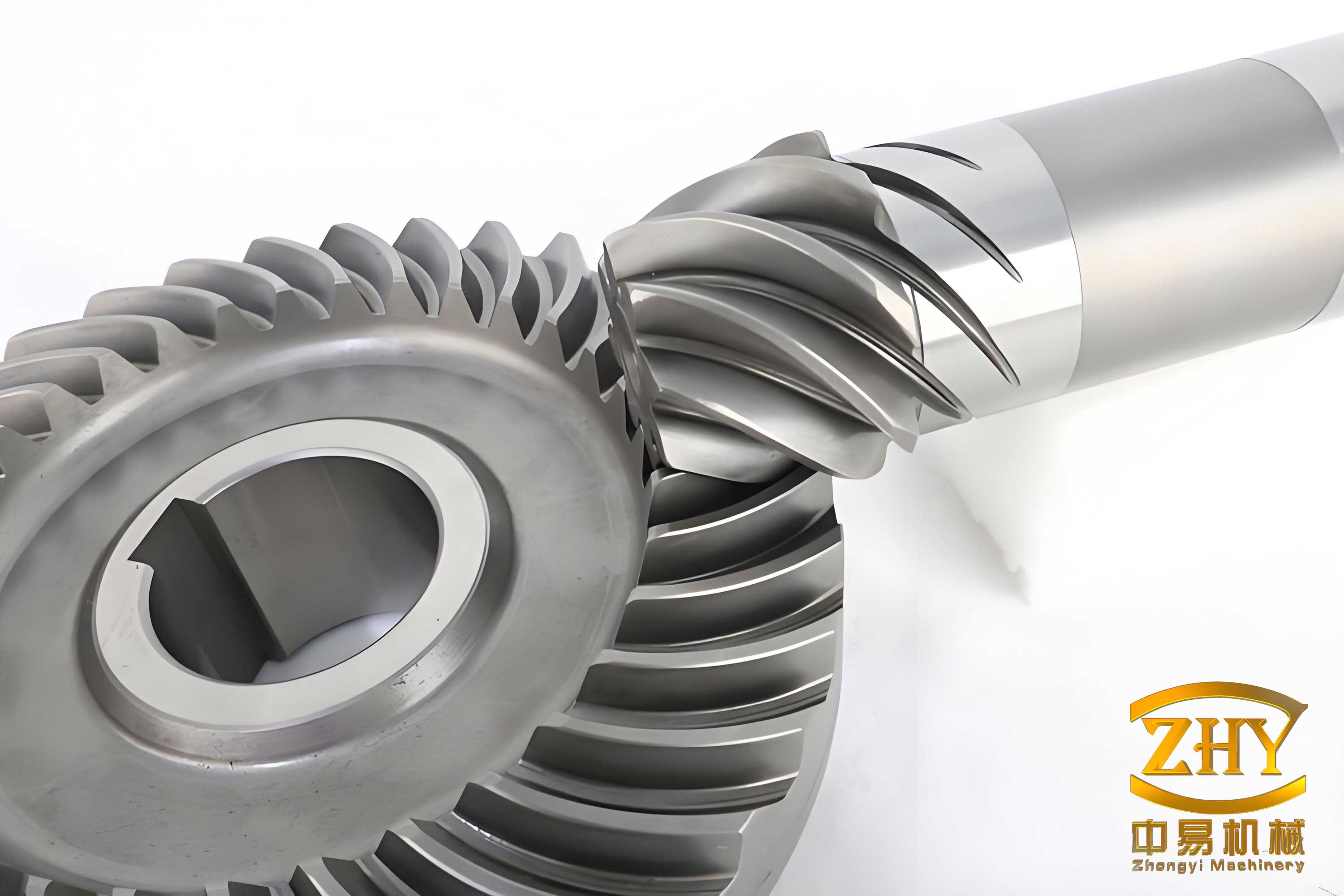
Spiral bevel gears are fundamental components in the power transmission systems of automotive drive axles, prized for their high overlap ratio and operational efficiency. A critical post-machining requirement for these gears is the chamfering of the sharp tooth profile edges. These sharp edges, if left untreated, are prone to causing nicks and dents during handling and assembly, and can significantly contribute to gear noise and vibration during operation. The conventional and widely adopted method in many manufacturing settings involves the use of dedicated chamfering machines. While functional, this approach relies heavily on manual skill for the complex setup and continuous adjustment of grinding wheels due to wear. This process is not only time-consuming but also introduces variability, making it challenging to maintain consistent chamfer quality across production batches and over time.
The evolution of multi-axis CNC gear milling machines presents a sophisticated alternative: performing the chamfering operation directly on the milling machine using a dedicated chamfering tool. In this integrated process, the tool follows a pre-calculated, continuous path along the tooth profile edge. This method ensures remarkable consistency in the chamfer geometry, eliminates the need for secondary material handling between machines (thereby saving time and labor), and leverages the precision of the CNC system. However, the successful implementation of this strategy hinges on the precise design of the chamfering tool itself and the generation of its corresponding tool path. Specialized software, such as KIMoS (Klingelnberg Integrated Manufacturing and Optimization Software), is essential for this purpose, enabling the virtual design, simulation, and optimization of both the tool and the machining process before physical implementation.
Classification and Characteristics of Chamfering Tools
The selection of a chamfering tool is intrinsically linked to the type of gear milling machine (horizontal or vertical spindle) and the desired chamfering strategy. The three primary categories are detailed below and compared in Table 1.
- Solid Chamfering Cutter: This is a monolithic tool designed primarily for horizontal-spindle machines. The chamfering process is continuous, with the tool tracing the profile from the toe to the heel. A significant limitation is potential collision between the tool body and the workpiece, often restricting its use to chamfering only the concave side of the gear’s heel.
- Blade-Type Chamfering Cutter: This design features a cutter head that holds individual, indexable blade segments. It offers greater flexibility and is suitable for both horizontal and vertical-spindle machines. Through careful design of the cutter head geometry (including eccentric mounting), it can perform continuous chamfering on both concave and convex sides, as well as at both the heel and toe ends of the spiral bevel gear tooth. This versatility makes it the most widely applicable solution.
- Chiseling-Type Tool: This simpler tool, used on horizontal machines, employs a single-point blade for a non-continuous, pecking motion. While cost-effective, this intermittent cutting action typically results in a poorer surface finish on the chamfered edge compared to continuous methods.
| Tool Type | Typical Machine Suitability | Process Nature | Chamfering Capability | Surface Finish |
|---|---|---|---|---|
| Solid Cutter | Horizontal Spindle (e.g., C27, C42) | Continuous | Primarily heel, concave side | Good |
| Blade-Type Cutter | Horizontal & Vertical Spindle (e.g., C29, C50) | Continuous | Heel & Toe, Concave & Convex | Very Good |
| Chiseling Tool | Horizontal Spindle (e.g., C27, C42) | Intermittent | Limited | Fair to Poor |
Table 1: Comparison of Chamfering Tool Types for Spiral Bevel Gears.
Design Methodology for Blade-Type Chamfering Tools
The design of a blade-type chamfering cutter is a multi-parameter optimization problem. It involves defining the cutter body geometry, the cutting insert (blade) geometry, and the kinematic parameters that govern the tool’s path relative to the spiral bevel gear. The following sections break down these critical parameters.
Cutter Body and Kinematic Design Parameters
The cutter body acts as the holder for the blades and defines the working envelope of the tool. Key parameters include:
- Cutter Diameter (Dc): Selected based on the machine model and gear size. Standard diameters exist for common machine interfaces (e.g., D55 for C50 machines). Eccentric cutter designs are often preferred as they allow for longer blade life and better clearance. The nominal diameter refers to the distance between opposing blade tips.
- Z-axis Offset (EZ): This is the horizontal distance between the axis of the chamfering cutter and the axis of the theoretical gear cutting tool (e.g., the face-mill cutter). It is crucial for avoiding collisions between the chamfering cutter body and the gear blank or its fixture. For pinions, EZ is typically minimized. For gears, a larger value can often be used. Its relationship with the gear blank’s outer diameter (Ra) and a required safety margin (δ) can be expressed as:
$$ E_{Z_{min}} \geq R_{a} + \frac{D_c}{2} + \delta $$
The tool path is defined by angular parameters that control the tool’s entry into and motion through the tooth space:
- Engagement Angle (φ): The angle between the direction of the cutter’s cutting velocity and the tooth flank at the initial contact point. It determines how gradually the tool enters the cut. A typical range is 30° to 45°. A smaller angle (e.g., 30°) is used when the starting point of the path is nearly tangent to the face cone of the spiral bevel gear.
- Lead Direction Entry Angle (ψ): The projection of the engagement angle onto the plane perpendicular to the root line. It defines the initial contact angle along the tooth’s lengthwise direction. Optimizing cutting conditions favors a larger ψ, but it is limited to about 45° to avoid collision with the opposite flank of the tooth slot. A common default is 30°.
- Profile Direction Entry Angle (Δα): The angle in the tooth profile direction between the contact point and the local pressure line. For gears cut by a continuous generating method or with crowned profiles, a value of 20°-25° is typical. For formate-cut gears with straight profiles, 10° may suffice. Excessive Δα risks cutter-gear interference.
- Fixture Safety Distance (SK): A minimum allowable distance enforced in the software between the chamfering cutter’s center and any part of the workpiece fixture during the entire tool path, preventing costly collisions.
| Parameter | Symbol | Typical Range / Value | Primary Influence |
|---|---|---|---|
| Cutter Diameter | Dc | Φ75-Φ160 mm (model dependent) | Machine compatibility, rigidity |
| Z-axis Offset | EZ | Gear-dependent (minimized for pinions) | Avoids body/blank collision |
| Engagement Angle | φ | 30° – 45° | Smoothness of tool entry |
| Lead Direction Entry Angle | ψ | 20° – 45° | Initial contact along tooth length |
| Profile Direction Entry Angle | Δα | 10° – 25° | Initial contact along tooth profile |
Table 2: Key Kinematic and Cutter Body Design Parameters.
Chamfering Blade Geometry Design
The blade geometry is simpler than that of a gear-cutting blade but must be precisely defined for manufacture and grinding. The main elements (Figure 1) are the rake face (C), the primary clearance face (A), and the secondary clearance face (B), which intersect to form the cutting edges.
- Blade Pressure Angles (αH, αN): The angles between the cutting edges and a reference plane. Since the blade does not generate the active gear flank, these angles are typically set to a small value (e.g., 10°) to maximize strength and simplify grinding, while ensuring non-interference with the finished spiral bevel gear tooth surface.
- Profile Height (HGH, HGN): The total flank height of the blade (cutting and non-cutting sides). Standardized based on cutter model for grinding convenience (see Table 3).
- Width Offset (aH): For a symmetrically ground blade, this is the distance from the blade’s mounting reference to the tip. It is calculated as half the total blade width: $$ a_H = \frac{b_0 + b_N}{2} $$
- Depth Setting (e): The perpendicular distance from the blade tip to its top mounting surface. This is a fixed value for a given cutter model to ensure proper positioning in the cutter head (see Table 3).
- Tip Radius/Cutting Edge Radius (RH): The radius of the blade’s cutting tip. It directly defines the size of the chamfer. A full-radius tip is often designed to distribute wear. The relationship between the desired chamfer width (Cw) and the tip radius for a 45° chamfer is approximately: $$ R_H \approx \frac{C_w}{\sqrt{2}} $$
- Rake and Clearance Angles (γ, αc): Due to the very small depth of cut in chamfering, these angles are frequently set to 0° to simplify the blade grinding process and increase edge strength.
| Cutter Model | Blade Size (W x H) mm | Profile Height (HGH) mm | Depth Setting (e) mm |
|---|---|---|---|
| D40S / D40X | 7.5 x 9 | 14 – 15 | 2.5 |
| D55S | 10.16 x 15.24 | ~25 | 5.08 |
| D55X / D85X | 7.5 x 9 | 20 | 2.5 |
Table 3: Standardized Blade Parameters for Common Cutter Models.
Design and Application Example
To illustrate the process, consider the design for chamfering a large spiral bevel gear (ring gear) from a heavy-duty truck axle drive. A D55X model cutter head is selected.
Step 1: Define Cutter Body & Kinematic Parameters. The software (e.g., KIMoS) is configured with the basic cutter data and the geometric model of the target spiral bevel gear. The kinematic parameters are set to achieve a balanced, interference-free tool path. An example set is shown in Table 4. The effective clearance (ζ) and rake (γ) angles at different points on the tooth are results calculated by the software based on the 3D kinematics, ensuring the cutting geometry is correct throughout the path.
| Parameter | Value |
|---|---|
| Cutter Diameter (Dc) | 110 mm |
| Number of Blades (Z) | 4 |
| Engagement Angle (φ) | 30.0° |
| Lead Entry Angle – Concave (ψconc) | 20.0° |
| Lead Entry Angle – Convex (ψconv) | 10.0° |
| Profile Entry Angle (Δα) | 10.0° |
Table 4: Example Cutter and Path Parameters for a Spiral Bevel Gear.
Step 2: Define Blade Geometry Parameters. The blade is designed according to the principles in Section 2.3. Key parameters for this example are listed in Table 5.
| Parameter | Symbol | Value |
|---|---|---|
| Blade Pressure Angle | αH | 10.0° |
| Profile Height | HGH | 20.0 mm |
| Width Offset | aH | 6.0 mm |
| Depth Setting | e | 1.863 mm |
| Tip Radius | RH | 1.700 mm |
Table 5: Example Blade Geometry Parameters.
Step 3: Tool Path Generation & Simulation. The software uses the combined data to calculate the continuous 5-axis tool path. This generates a series of machine-specific coordinate points (X, Y, Z, A, B for a 5-axis machine) that guide the cutter precisely along the tooth edge from heel to toe, and from the concave to the convex flank. A crucial advantage is the ability to simulate the entire process virtually to verify the absence of collisions and the quality of the resulting chamfer before any physical machining takes place.
Step 4: Blade Manufacturing, Assembly, and Inspection. The blade design data is exported to a CNC tool grinder (e.g., using a system like KIMoS in conjunction with a METeOR grinding machine). The blades are ground to the specified geometry. Since the positioning tolerance for chamfering blades is less critical than for gear-cutting blades, assembly into the cutter head can often be accomplished using standard gauge blocks for setting the protrusion, simplifying setup. The closed-loop manufacturing system allows for the grinding of replacement blades that are functionally identical to the original set, ensuring long-term process stability for the spiral bevel gear production line.
Step 5: Machining and Result. The final tool path is post-processed for the specific CNC gear mill (e.g., a C50 machine). The chamfering cutter, assembled with the ground blades, is mounted. The machine executes the programmed path, producing a uniform, high-quality chamfer on every tooth of the spiral bevel gear in a single, automated setup immediately after the teeth are cut, eliminating handling and secondary operations.
Process Advantages and Future Outlook
The methodology described offers significant advantages over traditional dedicated chamfering machines:
- Quality and Consistency: The CNC-guided continuous path guarantees that every chamfer on every spiral bevel gear is geometrically identical, eliminating human error and wheel-wear variation.
- Productivity and Flexibility: Integrating chamfering into the gear milling operation saves time associated with machine changeover, part handling, and the extensive setup of conventional machines. Tool path programs can be saved and recalled instantly for different gears.
- Reduced Skill Dependency: The process relies on software-based design and simulation, reducing the dependence on highly skilled technicians for manual setup and adjustment.
The future development of this technology points towards further integration and optimization:
- Unified Tool Design Databases: Research is ongoing to develop libraries of standardized, “universal” chamfering cutter and blade designs that can be efficiently adapted to a wider range of spiral bevel gear sizes and geometries, reducing the need for custom tooling for every new part number.
- Advanced Process Simulation: Incorporating physics-based simulation (e.g., cutting forces, thermal effects) into the tool path generation could further optimize parameters like feed rate to maximize tool life and surface finish.
- In-Process Monitoring: Integration of sensor systems to monitor tool wear or chamfer quality during the machining cycle could enable predictive maintenance and 100% quality assurance.
In conclusion, the design and application of dedicated chamfering tools for CNC gear milling machines, facilitated by advanced software like KIMoS, represents a superior manufacturing solution for spiral bevel gear finishing. It enhances quality consistency, operational efficiency, and process robustness, aligning with the demands of modern, high-volume precision gear manufacturing.