
Spiral bevel gears are fundamental transmission components, widely employed in critical applications such as aerospace, heavy-duty vehicles, and energy and marine equipment. The calculation of gear strength lies at the core of both gear standardization and product design. Internationally, the most widely applied standards are ISO 10300:2014 and ANSI/AGMA 2003-B97. The low implementation rate of standardized gear design methods across the industry leads to a lack of generality in the design outcomes for the same product when different standards are employed. This paper presents a comprehensive comparative study of the contact and bending strength calculation methods for spiral bevel gears as defined by these two prominent standards. We investigate the differences in the definition, evaluation methods, and impact of design parameters and correction factors. The effects of key geometric and operational parameters on the calculated strength are systematically analyzed through multiple design cases. Finally, the results from the analytical standards are verified against three-dimensional finite element contact analysis, providing insights into the conservatism and applicability of each method for assessing the load capacity of spiral bevel gears.
1. Introduction and Background
The performance and reliability of spiral bevel gear drives are paramount in demanding mechanical systems. Accurate prediction of their contact (pitting) and bending (root) fatigue strength is essential for safe, compact, and durable design. Historically, the industry has relied on standardized calculation procedures derived from fundamental theories—Hertzian contact theory for surface durability and the Lewis cantilever beam model for tooth bending strength. Two of the most influential sets of standards are those published by the International Organization for Standardization (ISO) and the American Gear Manufacturers Association (AGMA).
While both aim to predict gear performance under load, they differ significantly in their philosophical approach, choice of reference geometry, formulation of governing equations, and the definition and valuation of numerous influencing factors (correction factors). These differences can lead to substantially divergent results—different calculated stress levels, safety factors, and ultimately, gear dimensions—for the same set of design inputs. This lack of uniformity poses challenges for global supply chains and design collaboration.
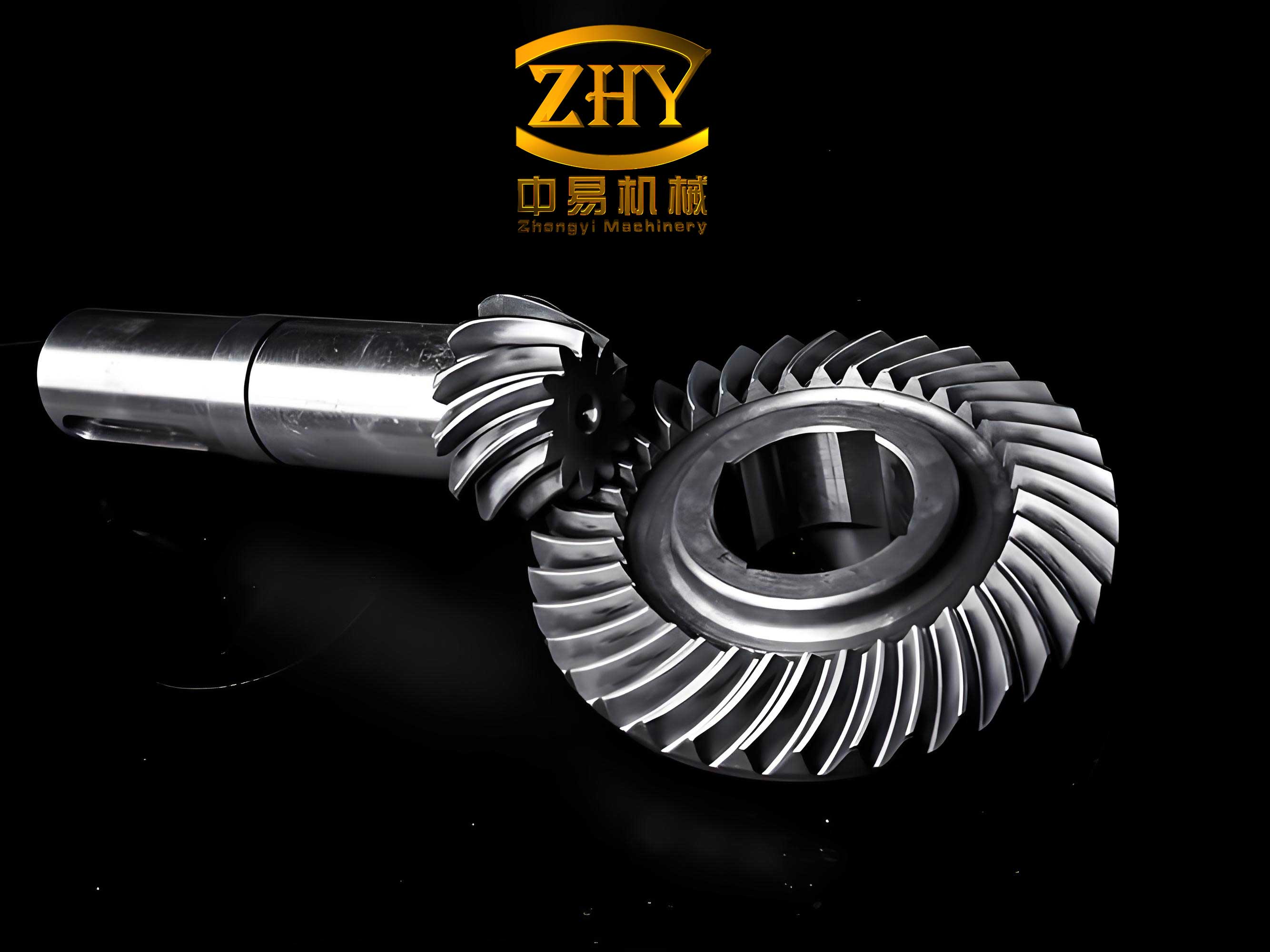
Previous comparative studies have largely focused on cylindrical gears. This work specifically addresses spiral bevel gears, considering the latest revisions of the standards (ISO 10300:2014 and AGMA 2003-B97) and accounting for the fundamental differences in material fatigue strength limits prescribed by each standard. Furthermore, modern finite element analysis (FEA) provides a powerful, physics-based tool to benchmark the results from these analytical standards, offering a deeper understanding of their predictive accuracy and inherent safety margins.
2. Comparative Analysis of Calculation Fundamentals
The foundational principles and reference systems used in the ISO and AGMA standards for spiral bevel gear strength calculation are fundamentally different. This section outlines these core differences, which cascade into all subsequent calculations.
ISO 10300:2014 Standard: The ISO standard performs strength calculations based on the geometry of an equivalent virtual cylindrical gear at the mean point of the tooth face width. For contact strength, the criterion is the maximum contact stress at the potential point of pitting initiation. For bending strength, the nominal tooth root stress is defined as the maximum tensile stress at the critical root fillet section, which is then adjusted by various correction factors to obtain the calculated stress. The standard provides separate factors for load distribution along the face width ($K_{H\beta}$, $K_{F\beta}$) and for load sharing between simultaneous pairs of teeth ($K_{H\alpha}$, $K_{F\alpha}$).
ANSI/AGMA 2003-B97 Standard: The AGMA standard uses the gear geometry at the outer (large end) as its primary reference. The contact stress calculation is based on the Hertzian stress between two contacting tooth surfaces, modified by factors accounting for load sharing and concentration. The bending stress calculation is derived from the Lewis formula applied to the tooth considered as a cantilever beam, with the critical section determined by a 30-degree tangent method. A single load distribution factor ($K_{H\beta}$) is used to account for both face load distribution and transverse load sharing effects in both contact and bending calculations.
This fundamental divergence in reference geometry—mean point versus outer point—is a primary source of discrepancy in the calculated stresses and the subsequent influence of geometric parameters.
3. Detailed Comparison of Strength Calculation Formulas
The governing equations for contact and bending strength in both standards are presented and dissected in this section. The formulas reveal significant differences in structure, parameters, and the integration of correction factors.
3.1 Contact Strength Formulas
The basic criterion for both standards is that the calculated contact stress $\sigma_H$ must not exceed the allowable contact stress $\sigma_{HP}$.
ISO 10300 Contact Stress:
$$\sigma_H = \sqrt{ \frac{F_{mt}}{l_{bm} \rho_{rel} } \cdot \frac{1}{\cos\alpha_n \cos\beta_{m1}} } \cdot Z_{M-B} \cdot Z_{LS} \cdot Z_E \cdot Z_K \cdot \sqrt{K_A K_V K_{H\beta} K_{H\alpha}}$$
where the nominal tangential load at the mean point is $F_{mt} = 2000 T_1 / d_{m1}$.
The allowable contact stress is:
$$\sigma_{HP} = \sigma_{Hlim} \cdot Z_{NT} \cdot Z_X \cdot Z_L \cdot Z_R \cdot Z_V \cdot Z_W \cdot Z_{Hyp}$$
The contact safety factor is calculated as $S_H = \sigma_{HP} / \sigma_H \ge S_{H,min}$.
AGMA 2003 Contact Stress:
$$\sigma_H = Z_E \sqrt{ \frac{2000 T_1}{b d_{e1}^2} \cdot \frac{Z_I}{Z_R} } \cdot \sqrt{K_A K_V K_{H\beta} Z_{XC}}$$
The allowable contact stress is:
$$\sigma_{HP} = \sigma_{Hlim} \cdot \frac{Z_{NT} \cdot Z_W}{S_H \cdot K_{\theta} \cdot Z_Z}$$
AGMA also defines an allowable power rating $P_{az}$ based on this stress.
Comparative Summary (Contact):
| Aspect | ISO 10300 | AGMA 2003-B97 |
|---|---|---|
| Reference Geometry | Mean point parameters ($d_{m1}$, $F_{mt}$, $\rho_{rel}$) | Outer point parameters ($d_{e1}$, $T_1$) |
| Load Distribution | Separate factors $K_{H\beta}$ (face), $K_{H\alpha}$ (transverse) | Single combined factor $K_{H\beta}$ |
| Core Formula Structure | Many factors outside the radical | Most factors inside the radical |
| Allowable Stress Factors | Includes lubrication ($Z_L$), roughness ($Z_R$), speed ($Z_V$), size ($Z_X$) | Includes temperature ($K_{\theta}$), reliability ($Z_Z$), hardness ratio ($Z_W$) |
| Safety Evaluation | Calculated safety factor $S_H$ vs. minimum $S_{H,min}$ | Direct comparison $\sigma_H \le \sigma_{HP}$ or via power $P_{az}$ |
3.2 Bending Strength Formulas
The basic criterion is that the calculated bending stress $\sigma_F$ must not exceed the allowable bending stress $\sigma_{FP}$.
ISO 10300 Bending Stress:
$$\sigma_F = \frac{F_{vmt}}{b_v m_{mn}} \cdot Y_{Fa} Y_{Sa} Y_{\epsilon} Y_{BS} Y_{LS} \cdot K_A K_V K_{F\beta} K_{F\alpha}$$
where $F_{vmt} = F_{mt} \frac{\cos\beta_v}{\cos\beta_{m1}}$ is the tangential force on the virtual cylindrical gear.
The allowable bending stress is:
$$\sigma_{FP} = \sigma_{Flim} \cdot Y_{ST} \cdot Y_{NT} \cdot Y_{\delta relT} \cdot Y_{RrelT} \cdot Y_X$$
The bending safety factor is $S_F = \sigma_{FP} / \sigma_F \ge S_{F,min}$.
AGMA 2003 Bending Stress:
$$\sigma_F = \frac{2000 T_1}{b d_{e1} m_{et}} \cdot K_A K_V \cdot \frac{K_{H\beta}}{Y_{\beta} Y_J} \cdot Y_X$$
The allowable bending stress is:
$$\sigma_{FP} = \sigma_{Flim} \cdot \frac{Y_{NT}}{S_F \cdot K_{\theta} \cdot Y_Z}$$
AGMA also defines an allowable power rating $P_{ay}$ for bending.
Comparative Summary (Bending):
| Aspect | ISO 10300 | AGMA 2003-B97 |
|---|---|---|
| Reference Geometry | Mean point virtual gear ($m_{mn}$, $d_{m1}$, $b_v$) | Outer point parameters ($m_{et}$, $d_{e1}$) |
| Tooth Form Factor | Combination $Y_{Fa} Y_{Sa}$ (form & stress correction) | Single geometry factor $Y_J$ |
| Load Distribution | Separate factors $K_{F\beta}$, $K_{F\alpha}$ | Uses contact load factor $K_{H\beta}$ |
| Size Factor | $Y_X$ in allowable stress (material dependent) | $Y_X$ in calculated stress (geometry dependent) |
| Allowable Stress Factors | Includes relative notch sensitivity ($Y_{\delta relT}$), surface condition ($Y_{RrelT}$), test gear factor ($Y_{ST}$) | Includes temperature ($K_{\theta}$) and reliability ($Y_Z$) |
4. Comparative Analysis of Key Correction Factors
The valuation of correction factors is a major source of difference between the two standards for spiral bevel gear strength rating. Their definitions and empirical bases often diverge.
4.1 Contact Strength Factors
Dynamic Factor ($K_V$): Both standards account for internal dynamic loads due to manufacturing inaccuracies and resonances, but with different formulas tied to their respective quality grading systems (ISO accuracy grade $C$ vs. AGMA quality number $Q_v$).
$$K_{V,ISO} = \left( \frac{A}{A + \sqrt{200 v_{et}}} \right)^{-X} \quad \text{with } A=50+56(1.0-X), X=0.25(C-4.0)^{0.667}$$
$$K_{V,AGMA} = \left( \frac{A}{A + \sqrt{200 v_{et}}} \right)^{-B} \quad \text{with } A=50+56(1.0-B), B=0.25(12-Q_v)^{0.667}$$
For the same operational conditions, these can yield different values.
Face Load Distribution Factor ($K_{H\beta}$): ISO uses an application factor $K_{H\beta-be}$ based on mounting conditions, typically leading to $K_{H\beta}=1.5 K_{H\beta-be}$. AGMA uses an empirical formula based on face width $b$ and a mounting factor $K_{mb}$: $K_{H\beta} = 1.5 K_{mb} + 5.6 \times 10^{-6} b^2$ for crowned teeth (doubled for uncrowned teeth). The AGMA formula inherently includes a crowning ($Z_{XC}$) effect.
Size Factor ($Z_X$, $Y_X$): In ISO, the contact size factor $Z_X$ is typically 1 for spiral bevel gears. In AGMA, the size factor for contact is often implicitly included in other factors or taken as 1, but a separate size factor for geometry $Z_X$ (not in the formula above) can exist in power rating formulas.
Life Factor ($Z_{NT}$, $Y_{NT}$): The formulas or tables relating cycles to life factor differ between standards due to different underlying test data and statistical interpretations for spiral bevel gears.
Material Fatigue Limits ($\sigma_{Hlim}$, $\sigma_{Flim}$): This is a critical difference. For the same material and heat treatment (e.g., Grade 2 carburized steel), the listed fatigue strength limits in the two standards are not aligned. AGMA values tend to be higher for contact and lower for bending compared to ISO values for nominally equivalent materials. This directly impacts the allowable stress $\sigma_{HP}$ and $\sigma_{FP}$.
4.2 Bending Strength Factors
Size Factor ($Y_X$): The treatment is reversed. ISO includes $Y_X$ in the allowable stress $\sigma_{FP}$, and it is a function of material and mean normal module $m_{mn}$ (see Table below). AGMA includes $Y_X$ in the calculated stress $\sigma_F$, and it is a function of outer transverse module $m_{et}$ only: $Y_X = 0.5$ for $m_{et} < 1.6$ mm, otherwise $Y_X=0.4867 + 0.008399 m_{et}$.
| Material | $m_{mn} \le 5$ mm | $5 < m_{mn} \le 25$ mm | $m_{mn} > 25$ mm |
|---|---|---|---|
| Through-hardened steels, QT steels | 1.0 | $Y_X = 1.03 – 0.006 m_{mn}$ | 0.85 |
| Case-hardened steels | 1.0 | $Y_X = 1.05 – 0.01 m_{mn}$ | 0.8 |
Tooth Form Factors: ISO uses a two-coefficient system: the form factor $Y_{Fa}$ (geometry) and the stress correction factor $Y_{Sa}$ (notch effect). AGMA combines these into a single geometry factor $Y_J$, derived from layout charts or software, which also incorporates the effects of load position and stress concentration for spiral bevel gears.
5. Parametric Study and Results from Standards
To illustrate the practical impact of these differences, five cases of spiral bevel gear pairs are analyzed using both standards. The baseline geometry is defined, and key parameters are varied one at a time. The gears are assumed to be of Grade 2 steel, with a face width of 30 mm, input power of 20 kW, and a required life of $10^7$ cycles. For a consistent comparison, safety factors are computed for both standards using the ratio of allowable stress to calculated stress ($S_H = \sigma_{HP}/\sigma_H$, $S_F = \sigma_{FP}/\sigma_F$), even though AGMA does not formally define a “calculated” safety factor in this manner.
| Case | Pinion Teeth $z_1$ | Gear Teeth $z_2$ | Outer Module $m_{et}$ (mm) | Spiral Angle $\beta$ (°) | Speed $n_1$ (rpm) |
|---|---|---|---|---|---|
| 1 (Baseline) | 40 | 80 | 3 | 35 | 1000 |
| 2 (Higher Ratio) | 40 | 100 | 3 | 35 | 1000 |
| 3 (Larger Module) | 40 | 80 | 4 | 35 | 1000 |
| 4 (Lower Spiral Angle) | 40 | 80 | 3 | 25 | 1000 |
| 5 (Higher Speed) | 40 | 80 | 3 | 35 | 1500 |
The calculated safety factors for contact ($S_H$) and bending ($S_F$) are presented below:
| Case | ISO Contact $S_H$ | AGMA Contact $S_H$ | ISO Bending $S_F$ | AGMA Bending $S_F$ |
|---|---|---|---|---|
| 1 | 1.049 | 1.351 | 2.226 | 1.046 |
| 2 | 1.098 | 1.420 | 2.302 | 1.093 |
| 3 | 1.399 | 1.791 | 3.560 | 1.811 |
| 4 | 0.975 | 1.216 | 2.035 | 0.994 |
| 5 | 1.262 | 1.642 | 3.221 | 1.546 |
Observations:
- Consistent Discrepancy Trend: For all cases, AGMA predicts a higher contact safety factor than ISO, while ISO predicts a significantly higher bending safety factor than AGMA. This is a direct consequence of the differences in both calculated stress formulas and, more importantly, the material fatigue limits.
- Parameter Sensitivity: Increasing the gear ratio (Case 2), outer module (Case 3), or speed (Case 5) generally increases both contact and bending safety factors in both standards. The effect of increasing the module is particularly pronounced.
- Spiral Angle Effect: Reducing the spiral angle from 35° to 25° (Case 4) decreases the safety factors, bringing the ISO contact safety factor below 1. This highlights the sensitivity of spiral bevel gear strength to this parameter and the different ways the standards account for it (via $Z_K$, $Y_{BS}$ in ISO and $Z_I$, $Y_{\beta}$ in AGMA).
The fundamental reason for the opposing trends in safety factors is the divergent material data. For example, for a typical case-hardened steel, ISO might specify $\sigma_{Hlim} \approx 1500$ MPa and $\sigma_{Flim} \approx 450$ MPa, while AGMA for a similar material might specify $\sigma_{Hlim} \approx 1650$ MPa and $\sigma_{Flim} \approx 380$ MPa. These differences in the baseline material strength, combined with the different calculation paths, lead to the observed discrepancies.
6. Finite Element Contact Analysis Verification
To provide an independent assessment, a detailed 3D nonlinear finite element contact analysis (FECA) was performed for the baseline spiral bevel gear pair (Case 1). A precise geometric model of the gear pair was generated based on cradle-style manufacturing settings. The model was meshed with predominantly hexahedral elements (C3D8R), with local refinement in the contact and root fillet regions. A multi-tooth segment model (4 tooth pairs) was used to capture load sharing. Frictionless surface-to-surface contact was defined between the pinion concave and gear convex flanks. Torque was applied gradually to the driven gear’s hub via a reference point using kinematic coupling, while the pinion was fully constrained except for rotation about its axis, simulating a quasi-static loading condition.
The FECA yielded a maximum contact stress of $\sigma_{H,FEA} = 522.4$ MPa and a maximum tensile bending stress at the root of $\sigma_{F,FEA} = 213.2$ MPa. These values are compared against the calculated stresses from the ISO and AGMA standards in the table below. Note that the AGMA calculated stresses are also shown adjusted by removing the crowning factor $Z_{XC}$ (set to 1) for a more direct comparison, as the FEA model had no intentional crowning.
| Method | Max Contact Stress $\sigma_H$ (MPa) | Max Bending Stress $\sigma_F$ (MPa) |
|---|---|---|
| Finite Element Analysis (FEA) | 522.4 | 213.2 |
| ISO 10300 Calculation | 554.7 | 204.2 |
| AGMA 2003 Calculation (Original) | 787.5 | 116.3 |
| AGMA 2003 Calculation (Adjusted*, $Z_{XC}=1$) | 556.9 | 162.8 |
*Adjusted AGMA stress: $\sigma_{H,adj} = \sigma_H / \sqrt{Z_{XC}}$ and $\sigma_{F,adj} = \sigma_F / \sqrt{Z_{XC}}$.
Analysis of Results:
- Contact Stress: The ISO calculated contact stress (554.7 MPa) is about 6% higher than the FEA result. The unadjusted AGMA stress is 51% higher than FEA, primarily due to the crowning factor $Z_{XC}>1$ used in the standard calculation. When this factor is normalized, the adjusted AGMA stress (556.9 MPa) aligns very closely with both the ISO and FEA results.
- Bending Stress: The FEA bending stress (213.2 MPa) is about 4% higher than the ISO calculation. The unadjusted AGMA calculation is 45% lower than FEA. Even after adjusting for the crowning factor, the AGMA value (162.8 MPa) remains about 24% lower than FEA. This indicates that the AGMA bending stress formulation, with its geometry factor $Y_J$ and size factor $Y_X$, predicts significantly lower root stresses for this spiral bevel gear geometry compared to the detailed FEA model and the ISO approach.
This verification underscores that while calculated stress values may differ, the ultimate assessment of a spiral bevel gear’s safety depends on the ratio of the material’s capability (allowable stress) to the structural demand (calculated stress), i.e., the safety factor. The FEA provides a valuable benchmark suggesting that for contact strength, both standards’ core stress calculations can be reasonably accurate when factors like crowning are accounted for equally. For bending, the predictions vary more significantly.
7. Conclusion
This comprehensive comparative analysis between ISO 10300:2014 and ANSI/AGMA 2003-B97 standards for spiral bevel gear strength calculation reveals significant methodological differences that lead to divergent design outcomes. The ISO standard employs a mean point virtual gear methodology with a extensive set of individually applied correction factors, while the AGMA standard uses an outer point reference with factors that are frequently combined and often rooted in extensive empirical data. The most critical differences lie in: 1) The definition and valuation of dynamic and load distribution factors, 2) The treatment of size effects, 3) The formulation of tooth geometry factors, and 4) The fundamental fatigue strength limits assigned to materials.
The parametric study clearly demonstrates that for the same spiral bevel gear design, AGMA typically yields higher contact safety factors and lower bending safety factors compared to ISO. This opposite trend is primarily driven by the different material fatigue limits embedded in each standard. Finite element contact analysis verifies that the core stress calculations can be of similar magnitude for contact when comparable assumptions are made, but may show greater variance for bending stress prediction.
Therefore, directly comparing calculated stress values $\sigma_H$ or $\sigma_F$ between the two standards is not meaningful for assessing the relative conservatism of a spiral bevel gear design. The safety factor ($S_H$, $S_F$), which incorporates both the calculated structural stress and the material’s allowable stress, provides a more coherent basis for comparison and for final design adjudication. Designers must be aware of these profound differences when selecting a standard, interpreting results from different sources, or transitioning designs between regulatory environments that favor one standard over the other. For critical applications of spiral bevel gears, using high-fidelity tools like finite element analysis as a supplement to standardized calculations is highly recommended to validate performance and optimize design margins.