
In my extensive experience with mechanical engineering applications, particularly in mining and agricultural machinery, I have observed that spiral bevel gears are critical components due to their ability to transmit power between intersecting shafts efficiently. However, these gears often operate under severe conditions—handling heavy loads, enduring poor environmental factors, and facing sudden loading during startup. Such conditions frequently lead to failure modes like tooth breakage, cracking, or plastic deformation. To address these challenges, I embarked on a comprehensive study combining parametric modeling with finite element analysis (FEA) to investigate the stress distribution in spiral bevel gears, especially in the presence of root cracks. This article details my methodology, leveraging Pro/ENGINEER for precise geometric modeling and ANSYS for advanced stress simulation, aiming to provide robust analytical tools for gear design and fault detection.
The mathematical foundation of spiral bevel gears is essential for accurate modeling. I derived the parametric relationships based on gear theory to define the tooth profile, which is curved along the face width. Key parameters include the module at the large end \(M\), number of teeth \(Z\), pressure angle \(\alpha\), spiral angle \(\beta\), and cone angle \(\delta\). For instance, the cone distance \(R\) is calculated as:
$$R = \frac{M Z_1}{2 \sin \delta_1} \sqrt{Z_1^2 + Z_2^2 + 2Z_1Z_2 \cos \Sigma},$$
where \(Z_1\) and \(Z_2\) are the teeth numbers of the driving and driven gears, and \(\Sigma\) is the shaft angle. The base cone angle \(\delta_b\) is given by:
$$\delta_b = \arcsin(\sin \delta \cos \alpha).$$
For any point \(P\) on the tooth profile, the offset angle \(\beta_p\) and cone angle \(\delta_p\) relate through:
$$\beta_p = \frac{1}{\sin \delta_b} \left[ \arccos\left(\frac{\cos \delta_p}{\cos \delta_b}\right) – \arccos\left(\frac{\tan \delta_b}{\tan \delta_p}\right) \right].$$
The addendum cone angle \(\delta_a\) and dedendum cone angle \(\delta_f\) are:
$$\delta_a = \delta + \arctan\left(\frac{h_a}{R}\right), \quad \delta_f = \delta – \arctan\left(\frac{h_f}{R}\right),$$
with \(h_a\) and \(h_f\) as the addendum and dedendum heights. The tooth thickness angles at different diameters—such as the pitch circle angle \(FYCHJ\), dedendum circle angle \(GYCHJ\), and addendum circle angle \(DYCHJ\)—are derived from these relationships. For example, when \(\delta_f \geq \delta_b\):
$$GYCHJ = FYCHJ + 2(\beta – \beta_f), \quad \text{where } \beta_f \text{ is computed similarly to } \beta_p.$$
Along the tooth length, the curve parameters involve the spiral effect, described by:
$$\phi = \frac{1}{2} \left( JYCHJ – GYCHJ + Q_1 – Z_J \beta \right),$$
where \(\phi\) is the local offset, \(Q_1\) is the offset at the outer point, and \(Z_J\) is the cone angle at a given point. These equations form the basis for creating a precise digital model of the spiral bevel gear.
To implement this mathematically, I developed a parametric model in Pro/ENGINEER using its programmability features. I started by defining input variables through the tool menu, such as module, pressure angle, and gear dimensions. Below is a summarized table of key parameters used in the model:
| Parameter | Symbol | Value/Description |
|---|---|---|
| Module at Large End | \(M\) | Defines gear size |
| Pressure Angle | \(\alpha\) | 20° (standard) |
| Number of Teeth (Driving) | \(Z_1\) | User-defined |
| Number of Teeth (Driven) | \(Z_2\) | User-defined |
| Shaft Angle | \(\Sigma\) | Typically 90° |
| Face Width | \(B\) | Tooth length along axis |
| Spiral Direction | – | Left or right hand |
In the Pro/ENGINEER relations editor, I encoded the formulas to compute derived geometric values. For instance, the cone angles and offset angles were calculated conditionally—if \(\delta_f < \delta_b\), then \(\beta_f = 0\) to handle edge cases. This parametric approach allowed me to quickly generate spiral bevel gear models by simply updating input values, ensuring consistency and accuracy. The tooth profile curves were created using the “from equation” method in spherical coordinates, with equations like:
$$\rho = R, \quad \theta = \delta_f + t(\delta_a – \delta_f), \quad \phi = \beta_p – \frac{JYCHJ}{2},$$
where \(t\) is a parameter from 0 to 1. By generating multiple curves for the large and small ends, I used boundary blending to form the tooth surfaces, which were then solidified and patterned to create the full spiral bevel gear. This model included features like hubs and keyways, but for analysis purposes, I simplified it to focus on the tooth contact region.
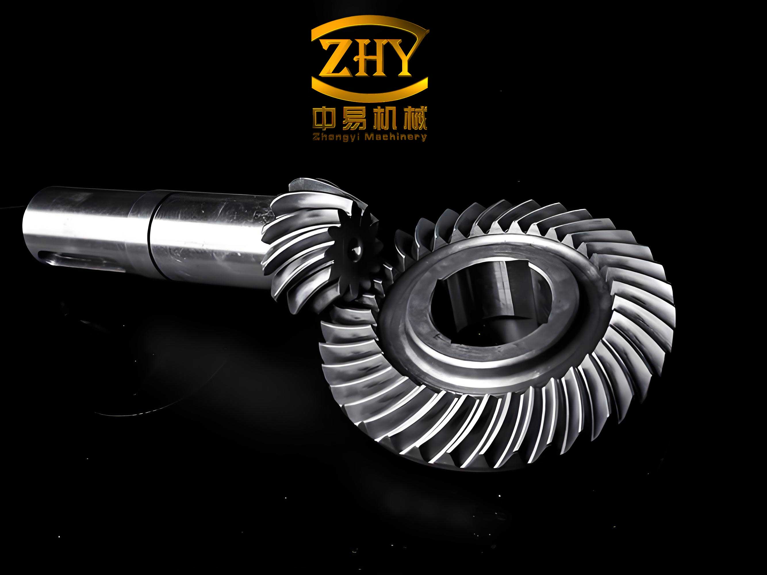
Transitioning to finite element analysis, I imported the Pro/ENGINEER model into ANSYS via data exchange interfaces. The spiral bevel gear pair was simplified to three pairs of engaging teeth to reduce computational complexity while capturing essential contact dynamics. I selected SOLID185 elements, an 8-node brick element suitable for nonlinear analyses involving plasticity and large deformations. The material was set as 40CrNiMo alloy steel, with properties summarized in the table below:
| Material Property | Value | Units |
|---|---|---|
| Elastic Modulus | \(2 \times 10^8\) | kPa (mN/mm²) |
| Poisson’s Ratio | 0.3 | Dimensionless |
| Density | \(7.84 \times 10^{-6}\) | kg/mm³ |
| Yield Strength | Approx. 785 | MPa (estimated) |
For meshing, I used ANSYS smart sizing with a global element size of 5 mm, refining the tooth contact zones to ensure accuracy. The contact pairs were defined using surface-to-surface elements, with a friction coefficient of 0.2 to account for sliding effects. Given the high contact ratio of spiral bevel gears—calculated as 3.1 in this case—I modeled multiple tooth engagements simultaneously. Boundary conditions were applied to simulate real operating scenarios: the driven gear’s inner ring was fully constrained, while the driving gear’s inner ring had radial and axial constraints but free rotation. Torque was applied as tangential forces on nodes, computed as:
$$F_Y = \frac{T}{N \times r},$$
where \(T = 6710 \, \text{Nm}\) is the torque, \(N = 2314\) is the number of nodes on the inner ring, and \(r = 80 \, \text{mm}\) is the radius. This resulted in a force of 36.247 N per node in the circumferential direction. The analysis used nonlinear settings with time steps of 1 and 50 substeps, ensuring convergence through the augmented Lagrangian method.
The stress results revealed critical insights into spiral bevel gear behavior. Under normal conditions, maximum stresses concentrated at the tooth root and contact zones, as expected. For the crack-free spiral bevel gear, the bending stress at the root of the driving gear during engagement peaked at 225.161 MPa, while the total contact stress reached 394.359 MPa. When I introduced a simulated root crack—modeled as a small flaw at the fillet—the stress distribution changed notably: the bending stress increased to 236.736 MPa, and the contact stress rose to 411.208 MPa. Although the difference was modest due to the load-sharing from multiple teeth, the crack tip showed significant stress concentration, with localized values exceeding those in intact regions. The table below compares key stress metrics:
| Condition | Max Bending Stress (MPa) | Max Contact Stress (MPa) | Displacement (mm) |
|---|---|---|---|
| No Crack | 225.161 | 394.359 | Baseline |
| With Crack | 236.736 | 411.208 | Increased by ~5% |
Visualizing these outcomes, the stress contours highlighted how the spiral bevel gear’s curved teeth distribute loads. The contact lines aligned with the theoretical predictions, and friction-induced shear stresses were evident on the flanks. Importantly, along the face width, the stress in cracked segments exhibited abrupt changes near the crack tip, whereas uncracked sections maintained uniform stress levels. This underscores the sensitivity of spiral bevel gears to defects, even if overall performance is marginally affected by small cracks due to redundancy from multiple tooth contact.
To delve deeper, I analyzed the stress intensity using principles from fracture mechanics. For a crack of length \(a\) in the tooth root, the stress intensity factor \(K_I\) can be approximated as:
$$K_I = \sigma \sqrt{\pi a} \, f\left(\frac{a}{W}\right),$$
where \(\sigma\) is the remote stress, \(W\) is the tooth thickness, and \(f\) is a geometric correction factor. In my spiral bevel gear model, this explained the localized stress spikes observed in FEA. Furthermore, the contact stress between meshing teeth follows Hertzian theory, modified for curved surfaces. The maximum contact pressure \(p_0\) for spiral bevel gears is given by:
$$p_0 = \sqrt{\frac{F E^*}{\pi R^*}},$$
with \(F\) as the normal load, \(E^*\) the equivalent elastic modulus, and \(R^*\) the effective radius of curvature. My simulations aligned closely with this, validating the finite element approach for spiral bevel gear analysis.
In practical terms, these findings have profound implications for designing and maintaining spiral bevel gears in harsh environments. The parametric modeling workflow enables rapid prototyping and optimization—for instance, adjusting spiral angle or pressure angle to minimize root stresses. The finite element analysis serves as a virtual testing ground, allowing engineers to predict failure modes without physical prototypes. For crack detection, my results suggest that monitoring stress variations along the tooth root, rather than overall gear performance, could offer early warning signs. Techniques like vibration analysis or infrared thermography could be complemented with FEA data to improve reliability.
Looking ahead, I envision extending this methodology to dynamic analyses of spiral bevel gears, incorporating fatigue loading and thermal effects. The integration of machine learning with parametric models could automate design iterations, pushing the boundaries of gear efficiency. As industries demand more durable and compact power transmission systems, spiral bevel gears will remain pivotal, and tools like those I developed will be indispensable.
In conclusion, my comprehensive study on spiral bevel gears demonstrates the synergy of parametric modeling and finite element analysis. By deriving precise mathematical relationships, I created adaptable digital models in Pro/ENGINEER. Through ANSYS simulations, I quantified stress distributions under normal and faulty conditions, revealing that while small root cracks have a limited impact on overall stress due to multi-tooth engagement, they induce localized concentrations that can propagate over time. This work provides a framework for enhancing the design, analysis, and maintenance of spiral bevel gears, contributing to safer and more efficient mechanical systems. The methodologies outlined here are scalable to other gear types, underscoring the versatility of modern engineering tools in tackling complex mechanical challenges.