
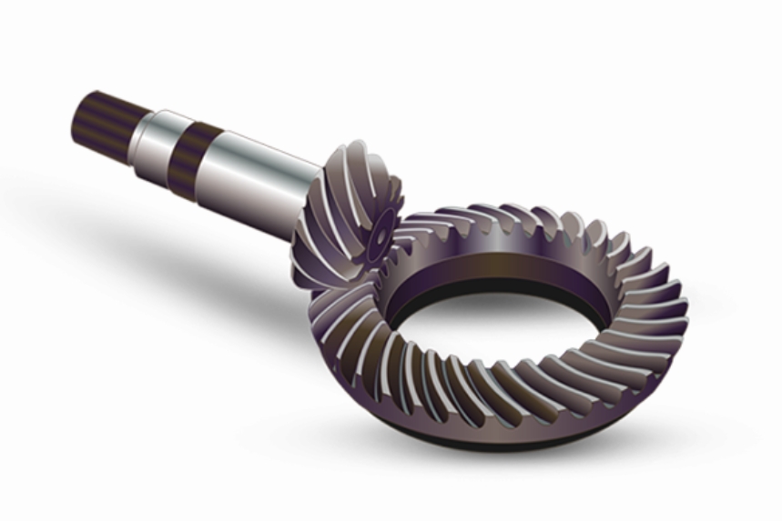
In the era of “Internet+” manufacturing, the demand for high-precision and high-efficiency production of spiral bevel gears has become increasingly critical. As a key component in automotive, agricultural machinery, and engineering equipment, the spiral bevel gear’s complex tooth surface geometry directly influences transmission efficiency, noise levels, motion accuracy, and service life. Traditional manufacturing methods often suffer from low information inheritance and integration during the digital closed-loop process, leading to isolated or semi-isolated design, machining, and inspection stages. To address these limitations, we propose a networked closed-loop manufacturing model for spiral bevel gears, aiming to achieve integrated operation and management of the entire tooth surface manufacturing process. This model leverages advanced technologies such as parametric design, computer numerical control (CNC) machining, digital measurement, and vibration-noise detection, all interconnected through a robust network infrastructure. By implementing this approach, we seek to enhance the precision and performance of spiral bevel gears, ultimately reducing production cycles and improving product competitiveness.
The core of our work revolves around the integration of various digital manufacturing resources into a cohesive system. The spiral bevel gear manufacturing process typically involves iterative steps of design, machining, measurement, and correction until the desired tooth surface accuracy is achieved. However, without effective networking and integration, these steps operate in silos, causing inefficiencies and inconsistencies. Our model establishes a networked environment where design systems, CNC machines, gear measuring centers, and vibration detection systems communicate seamlessly. This enables real-time data exchange, feedback correction, and centralized management, transforming the traditional closed-loop manufacturing into a dynamic, integrated workflow. The benefits include improved gear quality, reduced trial-and-error iterations, and better control over manufacturing parameters.
Our proposed networked closed-loop manufacturing model for spiral bevel gears consists of several key components: a communication network based on TCP/IP protocols, an information integration mechanism using Web services, and a centralized integration system for management. The communication network connects all participating devices, including CNC gear milling machines and gear measuring centers, through distributed integration control. For devices with serial interfaces, we employ serial port servers for protocol conversion, while those with native network interfaces are directly linked. This setup ensures reliable transmission of CNC programs and measurement data. The information integration mechanism utilizes Web services to encapsulate functionalities of various application systems, such as gear design software and measurement systems, allowing for cross-platform, loose-coupled integration. Through service description, publication, and discovery via UDDI registries, systems can invoke each other’s services using SOAP/XML messaging, facilitating seamless data flow. Finally, the integration system, developed with a service-oriented architecture, provides a unified platform for managing design, machining, measurement, and vibration-noise information. It features modules for system management, gear design management, tooth surface measurement management, CNC equipment management, and vibration-noise detection management, enabling holistic control over the spiral bevel gear manufacturing process.
The operation mode of our networked closed-loop manufacturing model follows a structured workflow. Initially, the gear design calculation system performs parametric design based on application conditions, including geometric parameter computation, strength verification, and toolpath generation for spiral bevel gears. Using methods like local synthesis, it calculates machine tool settings for both the gear and pinion, followed by tooth contact analysis (TCA) to optimize meshing performance. The design data, including machine adjustment parameters, are transmitted via the network to the integration system for management. Next, the CNC integration system retrieves this data to generate CNC machining programs, which are then sent to the CNC gear milling machine for trial cutting of the spiral bevel gear. After initial machining, the gear measuring center measures the tooth surface deviations in a grid pattern, compares them with theoretical values, and computes correction terms for the machine settings. These corrections are fed back to the CNC machine through the network for re-machining. This iterative process continues until the spiral bevel gear tooth surface meets accuracy standards. Subsequently, the vibration-noise detection system evaluates the gear pair’s dynamic performance on a rolling tester, with results used to further refine manufacturing parameters. All data from each stage are integrated into the central system, ensuring traceability and consistency for future production runs.
To elaborate on the technical details, we present key formulas and tables that summarize the manufacturing parameters and correction processes. For instance, the tooth contact analysis (TCA) for spiral bevel gears involves solving equations of meshing to predict contact patterns and transmission errors. A simplified representation of the TCA equation can be expressed as:
$$ \mathbf{r}_f(u, \theta) = \mathbf{r}_s(v, \phi) $$
where $\mathbf{r}_f$ and $\mathbf{r}_s$ are position vectors of the gear and pinion tooth surfaces, respectively, with parameters $u, \theta$ and $v, \phi$. This ensures proper meshing conditions. Additionally, the correction model for machine settings based on measured deviations can be formulated as a linear system:
$$ \Delta \mathbf{P} = \mathbf{J}^{-1} \cdot \Delta \mathbf{D} $$
Here, $\Delta \mathbf{P}$ represents the correction vector for machine settings (e.g., radial setting, cradle angle), $\mathbf{J}$ is the Jacobian matrix mapping setting changes to tooth surface deviations, and $\Delta \mathbf{D}$ is the measured deviation vector. This allows for precise adjustments in the spiral bevel gear manufacturing process.
In terms of practical implementation, we developed a networked system in our laboratory, connecting a YK2260T CNC spiral bevel gear milling machine, a JD45+ gear measuring center, and various software systems via a TCP/IP network. The integration system was built using Microsoft Visual Basic.NET and SQL Server 2005, featuring Web service interfaces for data exchange. We conducted trials on a hypoid gear pair to validate the model. The basic geometric parameters of the spiral bevel gear pair are summarized in Table 1.
| Parameter | Gear | Pinion |
|---|---|---|
| Number of Teeth | 37 | 6 |
| Module (mm) | 11.732 | 11.732 |
| Hand of Spiral | Right | Left |
| Offset (mm) | 30 | 30 |
| Mean Pressure Angle (°) | 22.5 | 22.5 |
| Mean Spiral Angle (°) | 34.4197 | 45.0331 |
| Face Width (mm) | 62 | 67.633 |
| Outer Diameter (mm) | 434.82 | 113.39 |
The machine tool settings for the spiral bevel gear pair, optimized through TCA, are listed in Table 2. These parameters were used for the initial CNC machining of the pinion spiral bevel gear.
| Parameter | Gear | Pinion Concave | Pinion Convex |
|---|---|---|---|
| Cutter Point Radius (mm) | 152.4 | 147.5 | 157 |
| Blade Angle (°) | 22.5 | 14 | -31 |
| Radial Setting (mm) | 151.4686 | 167.5145 | – |
| Cradle Angle (°) | 65.5431 | 58.8008 | – |
| Machine Center to Back (mm) | -2.2183 | -6.1839 | 8.2054 |
| Blank Offset (mm) | 29.8915 | 40.3261 | – |
| Sliding Base (mm) | 34.4803 | 44.5803 | – |
| Ratio of Roll | 5.8006 | 6.3550 | – |
After the first trial cut of the spiral bevel gear pinion, we measured tooth surface deviations using the gear measuring center. The maximum deviations were found to be -0.1591 mm on the concave side and 0.1352 mm on the convex side, indicating diagonal contact patterns. Based on these measurements, correction terms were computed using the deviation mapping model. The correction values for the pinion spiral bevel gear are shown in Table 3.
| Parameter | Pinion Concave | Pinion Convex |
|---|---|---|
| Radial Setting (mm) | 1.5220 | 4.0816 |
| Cradle Angle (°) | -0.3174 | -0.6147 |
| Machine Center to Back (mm) | -0.4996 | -0.2688 |
| Blank Offset (mm) | -0.6848 | -1.1863 |
| Sliding Base (mm) | -0.0479 | -0.0147 |
| Ratio of Roll | -0.0971 | -0.0795 |
After applying these corrections via networked feedback to the CNC machine, a second trial cut was performed. The resulting spiral bevel gear tooth surface deviations were significantly reduced, with maximum values of -0.0736 mm on the concave side and 0.0582 mm on the convex side, meeting the accuracy requirements. This demonstrates the effectiveness of the networked closed-loop correction process for spiral bevel gears.
To assess the meshing performance, we conducted vibration and noise tests on the spiral bevel gear pair using a rolling tester. The results showed that after correction, the overall radiation noise decreased from approximately (88 ± 2) dB to (82 ± 1.5) dB, a reduction of about 7%. Vibration analysis revealed that the acceleration amplitude at the primary meshing frequency (75 Hz) decreased by around 15%, indicating improved dynamic behavior. The contact pattern on the gear tooth surface also aligned well with theoretical predictions, confirming the enhanced quality of the spiral bevel gear manufactured through our networked system.
The implementation of our networked closed-loop manufacturing model for spiral bevel gears relies heavily on robust communication and integration mechanisms. The communication network is designed using a TCP/IP-based DNC (Distributed Numerical Control) mode. For CNC machines with serial interfaces, we use serial port servers that assign virtual COM ports and unique IP addresses, enabling them to communicate over the network. The CNC integration system manages these connections, supporting protocols like RTS/CTS and XON/XOFF for data flow control. This setup allows for seamless transmission of CNC programs and real-time monitoring. Additionally, the information integration mechanism employs Web services to bridge different application systems. Each system, such as the gear design software or measurement system, exposes its functionalities as Web services described in WSDL and registered in a UDDI registry. Other systems can discover and invoke these services using SOAP/XML messages. For example, the measurement system can retrieve machine settings from the design system via a Web service call, ensuring data consistency. The integration system acts as a central hub, providing a user interface for managing all spiral bevel gear manufacturing data. It is developed with a service-oriented architecture, allowing modules to interact through standardized interfaces without tight coupling. This design ensures scalability and flexibility, accommodating future upgrades or additional systems in the spiral bevel gear production line.
From a theoretical perspective, the correction process for spiral bevel gear tooth surface deviations can be modeled using sensitivity analysis. The relationship between machine setting changes and tooth surface deviations can be expressed as a linear approximation:
$$ \delta \mathbf{z} = \mathbf{S} \cdot \delta \mathbf{x} $$
where $\delta \mathbf{z}$ is the vector of tooth surface deviations at measured points, $\delta \mathbf{x}$ is the vector of machine setting adjustments, and $\mathbf{S}$ is the sensitivity matrix derived from the tooth surface generation model. For spiral bevel gears, this matrix is typically computed numerically through simulation or experimental data. By inverting this relationship, we can solve for the required adjustments to minimize deviations:
$$ \delta \mathbf{x} = \mathbf{S}^+ \cdot \delta \mathbf{z} $$
where $\mathbf{S}^+$ is the pseudo-inverse of $\mathbf{S}$, accounting for possible redundancies. This formulation underpins the automated correction in our networked system, enabling precise control over spiral bevel gear quality.
In terms of system architecture, the integration system comprises several modules: a database for storing spiral bevel gear design and manufacturing data, a Web service layer for interoperability, and a user interface for operational control. The database schema includes tables for gear parameters, machine settings, measurement results, and correction histories. The Web service layer implements functions such as “GetMachineSettings” or “SubmitMeasurementData,” which are called by various clients. The user interface provides dashboards for monitoring the status of CNC machines, viewing measurement reports, and managing production orders for spiral bevel gears. This integrated approach reduces manual intervention and errors, streamlining the entire manufacturing workflow.
Our experiments with the hypoid spiral bevel gear pair also highlighted the importance of iterative refinement. The initial trial cut produced deviations due to approximations in the design phase and machine tool inaccuracies. However, by leveraging networked feedback, we achieved convergence within two iterations. This efficiency gain is crucial for reducing time and cost in spiral bevel gear production, especially for small batches or custom designs. Furthermore, the vibration and noise test results validated that the corrected spiral bevel gear pair exhibited superior dynamic performance, which is essential for applications in automotive and aerospace industries where noise reduction is critical.
Looking ahead, the networked closed-loop manufacturing model for spiral bevel gears can be extended with advanced technologies such as artificial intelligence for predictive correction or cloud computing for remote monitoring. For instance, machine learning algorithms could analyze historical deviation data to predict optimal machine settings for new spiral bevel gear designs, further reducing trial cuts. Cloud-based platforms could enable collaborative manufacturing across multiple sites, sharing best practices and real-time data. These enhancements would continue to push the boundaries of precision and efficiency in spiral bevel gear manufacturing.
In conclusion, we have presented a comprehensive networked closed-loop manufacturing model for spiral bevel gears, integrating design, machining, measurement, and performance evaluation into a unified system. Through the implementation of a TCP/IP-based communication network, Web service-driven information integration, and a centralized management system, we achieved significant improvements in tooth surface accuracy and meshing performance for spiral bevel gears. Our application example demonstrated a reduction in noise and vibration, along with faster convergence to desired tolerances. This model not only addresses the limitations of traditional isolated manufacturing processes but also paves the way for smarter, more connected production environments. Future work will focus on enhancing the model with adaptive algorithms and expanding its applicability to other complex gear types. Ultimately, this research contributes to the advancement of digital manufacturing technologies for spiral bevel gears, offering a practical reference for industry adoption.