
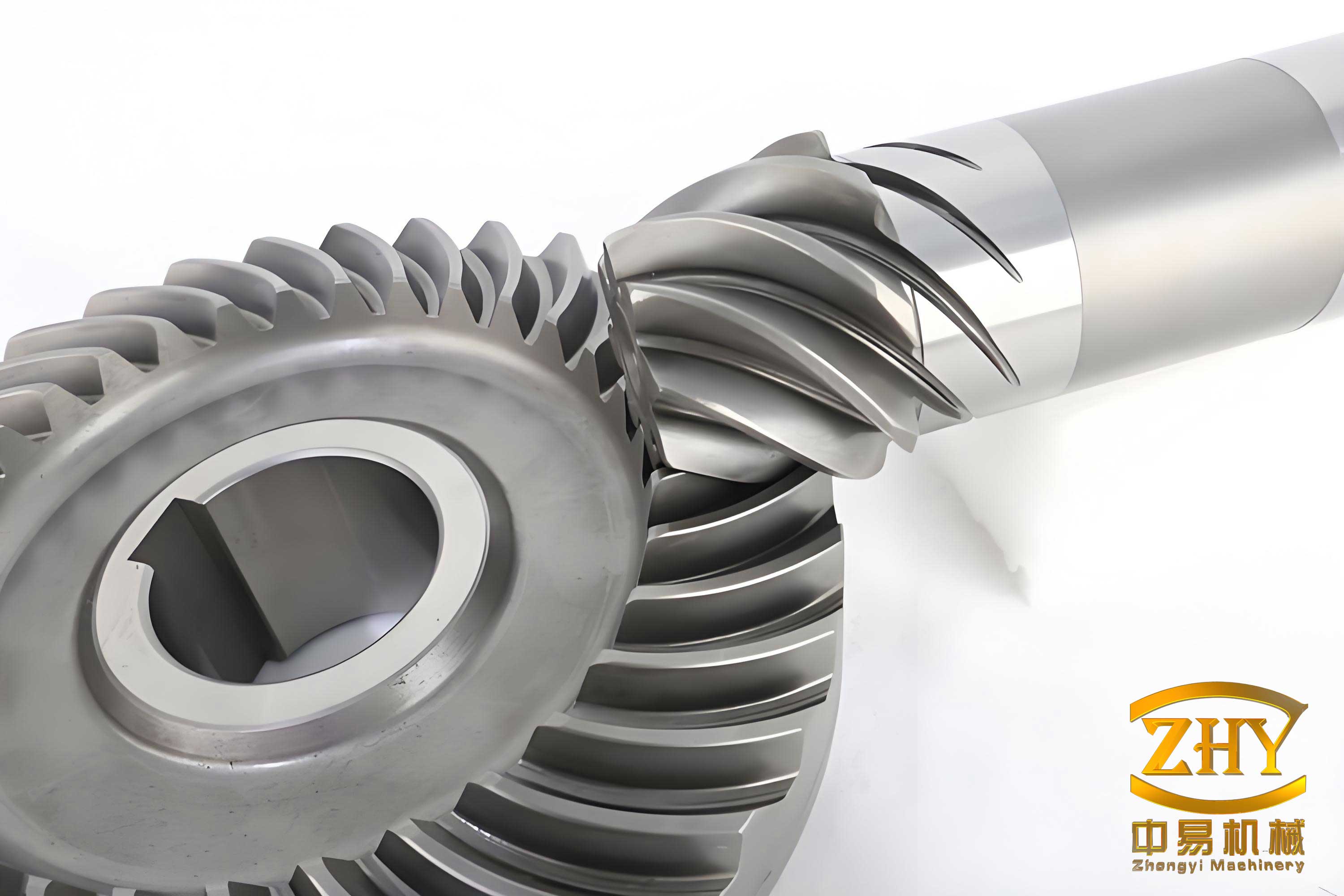
In modern aerospace propulsion systems, the demand for higher performance and efficiency has led to the widespread adoption of elastic support structures within rotor systems. These supports are designed to improve vibration characteristics and dynamic response. However, this design paradigm introduces significant challenges for power transmission components, particularly for central spiral bevel gear pairs. These gears are critical for transmitting power between intersecting shafts, such as from a gas turbine core to accessory gearboxes. Their performance is highly sensitive to the relative positioning of the pinion and gear axes. Under elastic support conditions, dynamic loads from rotor unbalance and static loads from gear meshing forces induce deflections at the supports. These defections alter the theoretical alignment of the gear axes, leading to deviations in tooth contact patterns and transmission errors, which can severely compromise reliability, increase noise, and accelerate failure. Therefore, ensuring the contact stability of spiral bevel gear transmissions—meaning the maintenance of a controlled, non-edge, and continuous contact pattern under all operational conditions—becomes a paramount concern for system reliability. This analysis focuses on establishing the methodology and stability criteria for analyzing these effects and proposes measures to enhance operational robustness.
Theoretical Foundation: Linking Support Deflection to Gear Meshing
1. Analysis of Support Deflection
Consider a typical aero-engine rotor model where the drive pinion of the central spiral bevel gear set is mounted on a rotor supported by an elastic front bearing and a rigid rear bearing. The driven gear is assumed to have relatively stiff supports, and its deflections are considered negligible for this analysis. The pinion support experiences composite deflections: static deformation due to the gear mesh load and dynamic response due to rotor unbalance.
The coordinate system $S_o(x_o, y_o, z_o)$ is established with its origin at the intersection point of the pinion and gear axes. The $z_o$-axis aligns with the pinion axis, pointing towards its large end. The $x_o$-axis aligns with the gear axis, and the $y_o$-axis is perpendicular to the plane formed by the two axes. The total deflection at the pinion apex (theoretical cone vertex) can be expressed in $S_o$ as a combination of linear and angular components:
$$ \delta_x = \Delta L_x + f_x(\theta) $$
$$ \delta_y = \Delta L_y + f_y(\theta) $$
$$ \delta_z = \Delta L_z $$
$$ \varepsilon_x = \Delta \alpha_x + \gamma_x(\theta) $$
$$ \varepsilon_y = \Delta \alpha_y + \gamma_y(\theta) $$
Here, $\Delta L_i$ and $\Delta \alpha_i$ (for $i = x, y, z$) represent the linear and angular deflections caused by the static gear meshing force. The terms $f_i(\theta)$ and $\gamma_i(\theta)$ represent the dynamic responses due to rotor unbalance, which are functions of the rotor’s angular position $\theta$ and rotational speed $\Omega$. These dynamic responses often trace an elliptical orbit and can be calculated using methods like the transfer matrix method for rotordynamics. For a simplified harmonic representation:
$$ f_x(\theta) = A_{x} \cos(\Omega t + \phi_{x}), \quad f_y(\theta) = A_{y} \sin(\Omega t + \phi_{y}) $$
$$ \gamma_x(\theta) = B_{x} \cos(\Omega t + \psi_{x}), \quad \gamma_y(\theta) = B_{y} \sin(\Omega t + \psi_{y}) $$
The amplitudes ($A_i, B_i$) and phases ($\phi_i, \psi_i$) are determined by the unbalance distribution, support stiffness, damping, and rotational speed, peaking significantly at critical speeds (resonances).
2. Tooth Surface Generation and Meshing Theory
The tooth surfaces of a spiral bevel gear pair are typically generated using face-milling or face-hobbing processes. The pinion (left-hand) and gear (right-hand) surfaces can be mathematically described in their respective tool coordinate systems, $S_1$ and $S_2$, using two parameters: the cutter rotation angle $\phi_c$ and the radial blade angle $\theta_c$.
Pinion Surface ($\Sigma_1$): $$ \vec{r}_1 = \vec{r}_1(\phi_{c1}, \theta_{c1}) $$
Gear Surface ($\Sigma_2$): $$ \vec{r}_2 = \vec{r}_2(\phi_{c2}, \theta_{c2}) $$
When the gear is positioned in the assembly coordinate system $S_o$ according to its theoretical design, its surface equation becomes $\vec{r}_2^{(o)} = M_{2o} \cdot \vec{r}_2$, where $M_{2o}$ is the coordinate transformation matrix.
For perfect conjugate action under ideal conditions, a point on $\Sigma_1$ and its corresponding point on $\Sigma_2$ must satisfy the condition of continuous tangency. This is governed by the equation of meshing:
$$ \vec{n} \cdot \vec{v}^{(12)} = 0 $$
where $\vec{n}$ is the common unit normal vector at the contact point, and $\vec{v}^{(12)}$ is the relative velocity between the two surfaces.
3. Effect of Support Deflection as Assembly Misalignment
In reality, elastic deflections cause the pinion to shift from its nominal position. This misalignment is kinematically equivalent to introducing deliberate assembly adjustments. The separation vector $\vec{\lambda}$ between a conjugate point on the pinion and gear in the pinion coordinate system $S_1$ due to misalignments $\Delta E$, $\Delta X$, and $\Delta \gamma$ is:
$$ \vec{\lambda} = \begin{bmatrix} -\Delta E \\ \Delta X \sin \Gamma – \Delta \gamma (R – r) \\ \Delta X \cos \Gamma \end{bmatrix} $$
Where:
$\Delta E$ = Offset along the pinion axis (positive towards large end).
$\Delta X$ = Offset along the gear axis (positive bringing gears closer).
$\Delta \gamma$ = Shaft angle error (angular misalignment in the plane of axes).
$\Gamma$ = Shaft angle.
$R$ = Distance from pinion apex to the pivot center for angular misalignment.
$r$ = Radial distance of the contact point.
The support deflections calculated earlier are directly mapped to these misalignment parameters:
$$ \Delta E = \delta_z $$
$$ \Delta X = \delta_x $$
$$ \Delta \gamma = \varepsilon_y $$
This critical transformation allows the dynamic rotor deflection problem to be incorporated into the static spiral bevel gear contact analysis framework. The condition for contact under load (also known as loaded tooth contact analysis) requires minimizing the separation $\vec{\lambda}$ subject to the equation of meshing, effectively finding the set of parameters $(\phi_{c1}, \theta_{c1}, \phi_{c2}, \theta_{c2})$ that satisfy:
$$ \vec{r}_1(\phi_{c1}, \theta_{c1}) + \vec{\lambda}(\Delta E, \Delta X, \Delta \gamma) \approx M_{12} \cdot \vec{r}_2(\phi_{c2}, \theta_{c2}) $$
and
$$ \vec{n}_1 \cdot \vec{v}^{(12)} = 0 $$
Solving this system yields the true path of contact across the tooth flank and the associated transmission error, defined as:
$$ TE(\phi_1) = \phi_2 – (\frac{N_1}{N_2}) \phi_1 $$
where $\phi_1$ and $\phi_2$ are the rotational angles of the pinion and gear, and $N_1$, $N_2$ are their tooth numbers.
Contact Stability Criteria and Analysis Methodology
The stability of contact for a spiral bevel gear under elastic support is evaluated against two primary failure modes: edge contact and discontinuous contact.
Stability Criterion 1: Avoidance of Edge Contact
The contact path must remain within the boundaries of the active tooth flank. This imposes constraints in both the profile (toe-heel) and lengthwise (face) directions.
Profile Boundary (Toe/Heel):
For a point on the pinion surface with coordinates $(y_1, z_1)$ in its face coordinate system, the condition to avoid contact at the ends is:
$$ -\frac{F}{2} \le y_1 \le \frac{F}{2} $$
where $F$ is the face width. A similar condition applies to the gear.
Lengthwise Boundary (Topland/Root):
To avoid contact at the tip or root, the radial distance of the contact point must be less than the outer radius and greater than the inner radius. For the pinion:
$$ r_{c1} \le R_{a1} $$
$$ L_{c1} \ge L_{c1\_min} $$
where $r_{c1}$ is the contact point radius, $R_{a1}$ is the pinion tip radius, and $L_{c1}$ is the distance from the apex.
Stability Criterion 2: Continuity of Contact (Convex Transmission Error)
A stable, smooth meshing action is characterized by a transmission error curve that is continuous and predominantly convex (parabolic-like). Discontinuous or highly concave segments indicate loss of contact or severe load sharing fluctuations. Mathematically, for stability, the second derivative of the transmission error function should not exhibit drastic sign changes or singularities over the mesh cycle:
$$ \frac{d^2(TE(\phi_1))}{d\phi_1^2} \text{ should be relatively smooth and bounded.} $$
A sudden “V” shape or step in the TE curve is a clear indicator of contact instability and potential tooth separation or impact.
Integrated Analysis Methodology
The complete analysis workflow integrates rotordynamics and gear contact mechanics:
- Rotor Dynamics Analysis: Calculate the dynamic unbalance response $f_i(\theta), \gamma_i(\theta)$ and static force deflection $\Delta L_i, \Delta \alpha_i$ of the pinion support for the operating speed range and specific power (torque) level. The transfer matrix method or finite element analysis is suitable.
- Deflection-to-Misalignment Transformation: Convert the calculated deflections into equivalent gear misalignment parameters $(\Delta E, \Delta X, \Delta \gamma)$ using the geometric relationships.
- Tooth Contact Analysis (TCA): Input the misalignment parameters into a spiral bevel gear TCA model. Solve the contact equations to determine the contact path (bearing pattern location and shape) and the transmission error curve for the given pinion rotation angle.
- Stability Evaluation: Check the contact path against the tooth boundaries (Criterion 1) and inspect the convexity and continuity of the TE curve (Criterion 2).
- Parametric Study: Repeat steps 1-4 across different operating speeds (especially near critical speeds), power levels (torques), and variations in elastic support stiffness to map the stability envelope.
Case Study: Numerical Analysis of a Representative Spiral Bevel Gear
To demonstrate the application of this methodology, we analyze a representative central spiral bevel gear pair from an aero-engine accessory drive. The key parameters are listed below.
| Parameter | Pinion (Driver) | Gear (Driven) |
|---|---|---|
| Number of Teeth | 25 | 41 |
| Hand of Spiral | Left Hand | Right Hand |
| Module (mm) | 4.5 | |
| Pressure Angle | 20° | |
| Mean Spiral Angle | 35° | |
| Shaft Angle | 90° | |
| Face Width (mm) | 38 | |
The rotor-bearing system is modeled with a front elastic support stiffness $K_{front}$ and a rigid rear support. The pinion is mounted at a specific distance from the front support.
Deflection Calculations
Using the transfer matrix method, the first critical speed of the rotor is identified. The deflections at the pinion support are computed for three key operational states: (1) At the first critical speed (resonance, with minimal damping), (2) At a low sub-critical operating speed, and (3) At the normal high-speed operating point. The results, combining both unbalance response and static load deflection, are summarized as equivalent misalignments.
| Operating Condition | $\Delta E$ (mm) Axial Offset | $\Delta X$ (mm) Offset | $\Delta \gamma$ (arc-min) Shaft Error | Primary Cause of Deflection |
|---|---|---|---|---|
| At First Critical Speed | 0.005 | 0.152 | 2.8 | Dominant dynamic unbalance response (elliptical orbit). |
| Low Operating Speed | 0.008 | 0.023 | 0.4 | Primarily static load deflection; small dynamic component. |
| Normal High Speed | 0.010 | 0.045 | 1.2 | Combination of static load and sub-critical dynamic response. |
Contact Pattern and Transmission Error Results
The misalignment values from Table 2 are input into the TCA model. The resulting contact patterns on the pinion tooth flank and the corresponding transmission error curves are analyzed qualitatively.
At First Critical Speed: The large $\Delta X$ and $\Delta \gamma$ values, resulting from resonant vibration, cause a severe shift of the contact pattern. The pattern moves significantly towards the toe and breaks over the edge in some positions during the mesh cycle. The transmission error curve shows large amplitude fluctuations and discontinuities, indicating periodic loss of contact and severe instability. This state is hazardous and should be traversed quickly during startup/shutdown.
At Low Operating Speed: The misalignments are small. The contact pattern is centered slightly towards the heel but remains well within the tooth boundaries. The transmission error is of low amplitude and exhibits a smooth, convex shape, indicating stable and continuous contact.
At Normal High Speed: The contact pattern shows a moderate shift towards the toe compared to the low-speed case. While it remains mostly on the active flank, it may lightly graze the edge under peak load conditions. The transmission error curve is still largely convex but shows increased amplitude and some higher harmonic content, suggesting reduced but acceptable stability.
| Condition | Contact Pattern Location | Edge Contact Risk | TE Curve Character | Stability Verdict |
|---|---|---|---|---|
| Critical Speed | Severe toe-ward shift, highly unstable. | High – Pattern breaks edge. | Discontinuous, high amplitude, non-convex. | Unstable |
| Low Speed | Centered, slight heel bias. | Very Low | Smooth, low amplitude, convex. | Very Stable |
| Normal High Speed | Moderate toe-ward shift. | Low-Moderate (potential edge touch). | Smooth, moderate amplitude, mostly convex. | Marginally Stable |
Discussion and Design Measures for Enhanced Stability
The analysis clearly demonstrates that the contact stability of a spiral bevel gear is highly dependent on the operational state of the elastically supported rotor. Resonance is the most critical condition. Based on this understanding, the following measures can be taken to improve the contact stability:
- Support Stiffness Optimization: The stiffness of the elastic support ($K_{front}$) is a key design variable. While a softer support improves overall rotor vibration isolation, it increases gear misalignment under mesh load. An optimal stiffness must be found that balances vibration attenuation with acceptable gear mesh misalignment. A sensitivity analysis, as part of the integrated methodology, can identify this optimum.
- Strategic Pinion Placement: Positioning the spiral bevel gear pinion closer to the rigid support (if possible) reduces the lever arm for both static and dynamic deflections. This directly minimizes the equivalent misalignments $\Delta \gamma$ and $\Delta X$, enhancing stability across all speeds.
- Gear Macro-Geometry Bias for Robustness: During the gear design phase, the inherent sensitivity to misalignment can be managed. The initial contact pattern under zero misalignment can be intentionally biased (e.g., slightly towards the heel) so that under the expected operational misalignments (especially at the normal high-speed condition), the pattern shifts into a centered, optimal position. This “pre-compensation” in the tooth surface geometry is a powerful tool for ensuring stable contact under load.
- Critical Speed Management: Ensuring a sufficient margin between the engine’s operating speed range and the rotor’s critical speeds is fundamental. If operation near a critical speed is unavoidable, increasing damping at the elastic support can dramatically reduce the amplitude of the dynamic response ($f_i, \gamma_i$), thereby mitigating the associated contact instability.
- Power/Speed Mapping: The analysis should be conducted over the entire engine operating envelope (different power settings at various speeds). Stability can be mapped, and operational limits or procedural guidance (e.g., limiting torque during acceleration through a critical speed) can be established to protect the spiral bevel gear transmission.
Conclusion
This integrated analysis establishes a clear methodological framework for assessing the contact stability of central spiral bevel gear transmissions operating within elastically supported rotor systems. The core of the method lies in the transformation of support deflections—comprising both static gear loads and dynamic unbalance responses—into equivalent gear misalignment parameters ($\Delta E, \Delta X, \Delta \gamma$). These parameters are then fed into a comprehensive tooth contact analysis model to predict the contact pattern and transmission error.
The stability of the gear mesh is rigorously defined by criteria avoiding edge contact and ensuring a continuous, convex transmission error curve. A case study demonstrates that while operation at a rotor’s critical speed induces severe contact instability due to large dynamic misalignments, proper design can ensure acceptable stability at normal operating speeds. The stability is not an inherent property of the gear pair alone but a system-level property resulting from the interaction between the rotor dynamics and the gear geometry.
Therefore, achieving reliable performance requires a concurrent design approach: the elastic support characteristics (stiffness, damping, location) and the spiral bevel gear tooth geometry must be co-optimized. By employing the proposed methodology during the design phase, engineers can proactively identify potential instability issues, evaluate design trade-offs, and implement measures such as support stiffness optimization, gear contact pattern bias, and critical speed margin management. This ensures that the high-performance benefits of elastic supports are realized without compromising the durability and smooth operation of the critical spiral bevel gear transmission.