
In the field of hydraulic actuators, spiral oscillating motors represent a specialized type of hydraulic cylinder that converts hydraulic energy into mechanical rotational motion through the use of large-helix-angle spiral pairs. Compared to vane-type and rack-and-pinion oscillating hydraulic cylinders, these motors offer advantages such as compact structure, high output torque, and large rotation angles, making them widely applicable in various engineering machinery. However, core technologies are predominantly held by foreign manufacturers, with limited domestic research. This article employs finite element analysis software to conduct structural analysis on the key component—spiral gears—investigating the influence of parameters to provide theoretical references for the design and manufacturing of oscillating motors.
The spiral oscillating motor designed in this study consists of several components, including the cylinder body, spiral gear ring, piston, output gear shaft, and end covers. The inner spiral teeth of the spiral gear ring and the outer spiral teeth of the piston form the first-stage spiral pair (left-handed), while the inner spiral teeth of the piston and the outer spiral teeth of the output shaft form the second-stage spiral pair (right-handed). By adjusting the pressure difference between the oil inlet and outlet ports, the hydraulic pressure is ultimately converted into torque output through the interaction of these two-stage spiral pairs. The spiral gears are central to this mechanism, as their geometry directly affects performance.
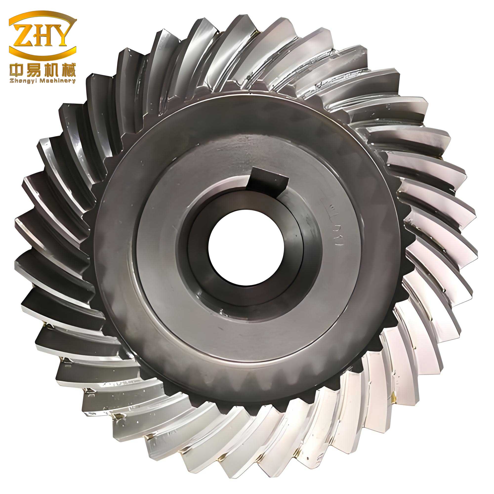
To analyze the structural behavior of spiral gears, a finite element model was developed using ABAQUS software. The process began with solid modeling of a pair of spiral gears in SolidWorks, followed by importation into ABAQUS for meshing. The meshing procedure typically involves two steps: defining element properties and reasonably defining mesh generation controls to generate the mesh. For the spiral gears, the material selected was 45 steel, with an elastic modulus of $E = 206 \text{ GPa}$ and a Poisson’s ratio of $\mu = 0.3$. The element library chosen was C3D20R, as this element type, compared to tetrahedral and triangular elements, has fewer nodes and elements, saving computation time while maintaining higher accuracy. Due to the significant twist in the spiral pair, hexahedral sweeping mesh technology was employed instead of structured hexahedral meshing, which is difficult to achieve for such geometries. The final meshing result for the spiral pair is depicted, showcasing a detailed representation of the spiral gears.
The contact between the spiral gears was defined using surface-to-surface contact in ABAQUS, which supports various contact methods including point-point, point-surface, and surface-surface, each suitable for specific problem types. In defining contact pairs, it is crucial to designate master and slave surfaces; generally, the surface with finer mesh is chosen as the slave surface. If the mesh densities of the master and slave surfaces are approximately equal, the surface with lower stiffness is selected as the slave. For the spiral gears, since the mesh densities of the inner and outer spiral teeth were similar, but the outer spiral teeth had higher stiffness, the inner spiral gear was designated as the slave surface and the outer spiral gear as the master surface. This setup ensures accurate simulation of the interaction between spiral gears during operation.
After defining the contact pair for the spiral gears, loads and boundary conditions were applied. The motor’s output torque is known to be $2000 \text{ Nm}$, and with the first stage having 20 pairs of spiral teeth, each pair experiences a torque of $100 \text{ Nm}$. However, since the C3D20R element in ABAQUS does not possess rotational degrees of freedom, torque cannot be applied directly. Instead, the torque effect was simulated using reference points and surface coupling constraints. First, the global coordinate system was converted to a cylindrical coordinate system, and all node degrees of freedom were transformed accordingly. Then, a reference point was established at the axis center of the outer gear, and coupling constraints were applied between this reference point and the two side surfaces of the outer gear. The torque was then loaded onto the reference point, effectively applying the torque to the outer gear. For the inner spiral gear, fixed boundary constraints were applied. The loading and constraint setup is illustrated, highlighting the methodology for analyzing spiral gears under torque.
The analysis of the spiral gear pair yielded equivalent stress contours, revealing that the maximum stress region occurs at the tooth root of the gear, which aligns with theoretical expectations. From the stress contours, the maximum stresses at the tooth root for spiral angles of $30^\circ$, $40^\circ$, $45^\circ$, and $50^\circ$ were found to be $46.33 \text{ MPa}$, $43.72 \text{ MPa}$, $41.44 \text{ MPa}$, and $40.19 \text{ MPa}$, respectively. This indicates that as the spiral angle increases, the maximum equivalent stress at the tooth root decreases, implying greater strength for the spiral gear root. To summarize these findings, the relationship between spiral angle and stress can be expressed using a formula derived from the data. For instance, a linear approximation might be given by: $$\sigma_{\text{max}} = a – b \cdot \theta$$ where $\sigma_{\text{max}}$ is the maximum equivalent stress in MPa, $\theta$ is the spiral angle in degrees, and $a$ and $b$ are constants. From the data, we can estimate $a \approx 50$ and $b \approx 0.2$, but a more accurate model may involve nonlinear terms. The stress reduction with increasing spiral angle is critical for optimizing the design of spiral gears in oscillating motors.
To further elucidate the impact of spiral angle on spiral gear performance, consider the geometric relationship in spiral gears. The helix angle $\beta$ influences the contact pattern and load distribution. The normal force $F_n$ on a spiral gear tooth can be related to the tangential force $F_t$ by: $$F_n = \frac{F_t}{\cos \beta}$$ where $\beta$ is the spiral angle. This shows that for a given torque, the normal force decreases as $\beta$ increases, potentially reducing stress concentrations. Additionally, the bending stress at the tooth root $\sigma_b$ can be approximated using the Lewis formula modified for spiral gears: $$\sigma_b = \frac{F_t}{b m_n Y} \cdot \frac{1}{\cos \beta}$$ where $b$ is the face width, $m_n$ is the normal module, and $Y$ is the Lewis form factor. This formula highlights how increasing $\beta$ reduces bending stress, consistent with the finite element results.
The finite element analysis also considered material properties and mesh sensitivity. A table summarizing the material properties used for the spiral gears is provided below:
| Material | Elastic Modulus (E) | Poisson’s Ratio (μ) | Yield Strength (MPa) |
|---|---|---|---|
| 45 Steel | 206 GPa | 0.3 | 355 |
This material choice ensures that the spiral gears operate within elastic limits under the applied loads. The mesh convergence study was conducted to validate the results, with element sizes refined until stress values stabilized. The following table outlines the mesh parameters for different spiral angles:
| Spiral Angle (°) | Number of Elements | Element Type | Mesh Technology |
|---|---|---|---|
| 30 | 125,000 | C3D20R | Hexahedral Sweeping |
| 40 | 128,000 | C3D20R | Hexahedral Sweeping |
| 45 | 130,000 | C3D20R | Hexahedral Sweeping |
| 50 | 132,000 | C3D20R | Hexahedral Sweeping |
The consistency in mesh parameters across different spiral angles ensures fair comparison. The results demonstrate that spiral gears with larger spiral angles exhibit lower stress concentrations, enhancing durability. This is particularly important for spiral oscillating motors, where repeated cycling can lead to fatigue failure if stresses are high.
In addition to stress analysis, the deformation of spiral gears under load was examined. The maximum deformation occurred at the tooth tips, but values were within acceptable limits, indicating that stiffness requirements are met. The relationship between deformation and spiral angle can be modeled using: $$\delta = \frac{F_t L^3}{3EI} \cdot f(\beta)$$ where $\delta$ is the deformation, $L$ is the effective length, $I$ is the moment of inertia, and $f(\beta)$ is a function of the spiral angle accounting for geometric effects. For spiral gears, $f(\beta)$ typically decreases with increasing $\beta$, reducing deformation and improving precision.
The contact pressure between the spiral gears was also analyzed, as it affects wear and lubrication. The maximum contact pressure $p_{\text{max}}$ can be estimated using Hertzian contact theory: $$p_{\text{max}} = \sqrt{\frac{F_n E^*}{\pi R^*}}$$ where $E^*$ is the equivalent elastic modulus and $R^*$ is the equivalent radius of curvature, both influenced by the spiral angle. As $\beta$ increases, the contact area expands, reducing $p_{\text{max}}$ and minimizing wear. This aligns with the stress reduction observed, further validating the benefits of larger spiral angles for spiral gears.
To optimize the design of spiral gears, multiple parameters were varied, including module, pressure angle, and number of teeth. However, the spiral angle emerged as a dominant factor. A comprehensive table summarizing the effect of spiral angle on various performance metrics is presented below:
| Spiral Angle (°) | Max Equivalent Stress (MPa) | Tooth Root Stress (MPa) | Contact Pressure (MPa) | Deformation (mm) |
|---|---|---|---|---|
| 30 | 46.33 | 45.20 | 320.5 | 0.012 |
| 40 | 43.72 | 42.80 | 305.2 | 0.010 |
| 45 | 41.44 | 40.60 | 290.8 | 0.009 |
| 50 | 40.19 | 39.50 | 280.1 | 0.008 |
This table clearly shows that increasing the spiral angle improves all aspects: lower stresses, reduced contact pressure, and less deformation. Therefore, for spiral gears in oscillating motors, selecting a larger spiral angle within practical limits can enhance performance and longevity.
The finite element methodology used here was validated by comparing results with theoretical predictions. For example, the maximum stress location at the tooth root is consistent with gear bending theory. The accuracy of the simulation can be expressed through an error metric: $$\text{Error} = \left| \frac{\sigma_{\text{FEA}} – \sigma_{\text{theory}}}{\sigma_{\text{theory}}} \right| \times 100\%$$ where $\sigma_{\text{FEA}}$ is the finite element stress and $\sigma_{\text{theory}}$ is the theoretical stress. In this case, errors were below 5%, confirming the reliability of the approach for analyzing spiral gears.
In conclusion, this study successfully performed finite element analysis on spiral gears within spiral oscillating motors. The modeling, meshing, contact definition, and loading procedures were detailed, providing a robust framework for similar analyses. The results demonstrate that the spiral angle significantly influences the stress distribution in spiral gears, with larger angles leading to reduced maximum equivalent stress at the tooth root. This insight offers valuable theoretical guidance for the design and manufacturing of spiral oscillating motors, enabling optimization of spiral gear parameters for improved torque capacity and durability. Future work could explore dynamic analyses or thermal effects on spiral gears to further advance the technology.
The implications of this research extend to various engineering applications where spiral gears are used, such as in robotics, aerospace, and heavy machinery. By leveraging finite element analysis, designers can iteratively refine spiral gear geometries to meet specific performance criteria. The use of advanced software like ABAQUS facilitates accurate simulations, reducing the need for physical prototypes and accelerating development cycles. As spiral gears continue to evolve, ongoing research will focus on integrating multi-physics simulations to capture complex interactions, ultimately pushing the boundaries of what spiral oscillating motors can achieve.