
The transmission system is a core component in mechanical equipment, and its performance directly affects the operational efficiency and service life of the entire machine. Among various transmission systems, the variable-speed transmission, as a key device for converting different speeds and torques, has always been a research hotspot in the field of mechanical engineering. The novel bevel gear-roller flat disk transmission provides an innovative solution for modern industrial drive systems with its unique structural design and transmission mechanism, characterized by high efficiency and stability. However, in practical applications, due to the complex and variable working environment, traditional control methods often struggle to ensure the stability and precision of constant speed output. Therefore, researching a control method capable of adaptive adjustment to achieve constant speed output is particularly important.
In recent years, scholars have achieved fruitful research results in the field of transmission control. For instance, one method predicts the speed output of a transmission under different clutch engagements via a system model and then optimizes the clutch engagement strategy based on the deviation between the predicted and desired speeds. However, due to system model uncertainties and external disturbances, this Model Predictive Control (MPC) method often exhibits significant control errors in practice. Furthermore, MPC demands high model accuracy; control performance degrades notably if model parameters change. Another study proposed a dual fuzzy PID control strategy for a Hybrid Mechanical Continuously Variable Transmission (HMCVT). This strategy combines the advantages of fuzzy and PID control by dynamically adjusting PID parameters via fuzzy logic for constant speed output. Nevertheless, the high design complexity of the dual fuzzy PID algorithm, requiring precise tuning of multiple fuzzy controller parameters, makes it difficult to achieve ideal control effects in real applications. Research on Continuously Variable Transmission (CVT) control based on driver intention adjusts the transmission’s speed output by monitoring driving behavior in real-time. Yet, the diversity and uncertainty of driver intent make it challenging to capture accurately, leading to considerable control errors. Optimization of fuzzy PID controller parameters using an Improved Particle Swarm Optimization (IPSO) algorithm has also been explored to enhance adaptability and robustness. However, issues like slow convergence and susceptibility to local optima in the IPSO algorithm itself hinder rapid and accurate parameter adjustment, affecting speed tracking precision and stability.
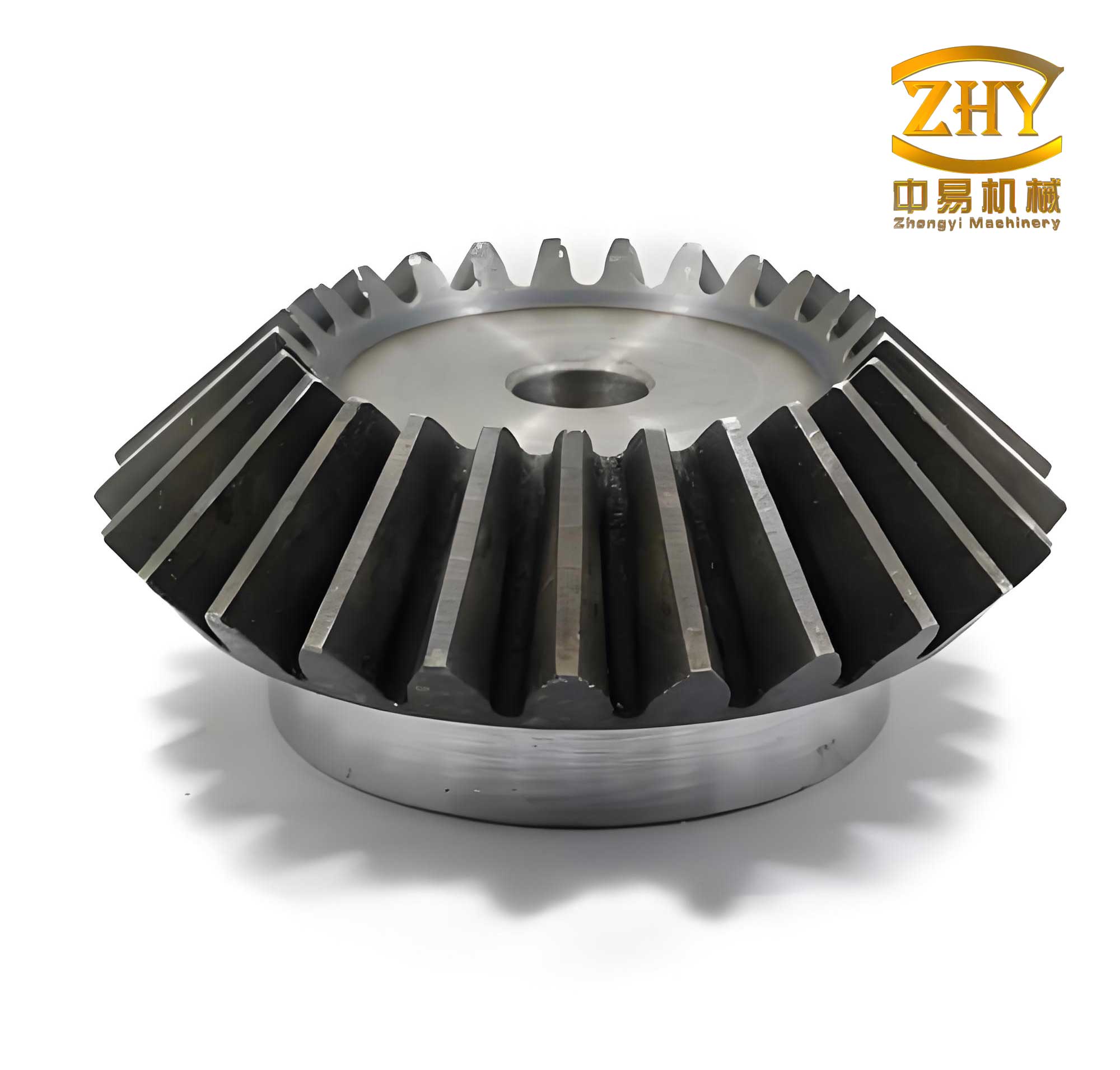
To address the nonlinear characteristics and uncertainties of the bevel gear-roller flat disk transmission system, a new constant speed output fuzzy PID control strategy is proposed. This strategy is designed to improve the control system’s adaptability and robustness.
Fuzzy PID Control for Constant Speed Output of the Novel Bevel Gear-Roller Flat Disk Transmission
1. Dynamic Modeling of the Novel Bevel Gear-Roller Flat Disk Transmission
The novel bevel gear-roller flat disk transmission combines bevel gear and roller-disk transmission mechanisms. Power transmission and speed variation are primarily achieved through the meshing of bevel gears and the rolling of rollers on a flat disk. The bevel gear section is responsible for changing the transmission ratio, while the roller-disk section ensures smooth torque transfer. Therefore, to achieve speed output control, dynamic modeling is first performed based on this transmission mechanism.
Assuming the input shaft speed of the bevel gear section is $$ \omega_{in} $$ and the output shaft speed is $$ \omega_{out} $$, the influence of load variation on the transmission ratio is considered by introducing a load coefficient $$ k_L $$. The transmission ratio $$ i $$ for the bevel gears can be expressed as:
$$ \begin{cases} i = \dfrac{\omega_{in}}{\omega_{out}} \\ i = \dfrac{N_1}{N_2} \cdot k_L(T_{out}) \end{cases} $$
where $$ k_L(T_{out}) $$ is a nonlinear function concerning the output torque, representing the load’s effect on the transmission ratio. $$ N_1 $$ and $$ N_2 $$ are the tooth numbers of the two bevel gears, respectively.
Next, modeling the roller-disk section. When a roller rolls on the flat disk, it is primarily subjected to friction force $$ F_f $$. Assuming the friction coefficient between the roller and the disk is $$ \mu $$ and the normal force exerted by the roller on the disk is $$ F_n $$. Considering that the rolling resistance torque relates not only to friction but also to the roller’s speed, acceleration, and material properties, a rolling resistance coefficient $$ f_r $$ is introduced. The rolling resistance torque $$ M_r $$ can be expressed as a function of these parameters:
$$ M_r = f_r(v, \alpha, F_n, \mu, \rho, R, …) $$
where $$ v $$ represents the roller’s linear velocity, $$ \alpha $$ represents the roller’s angular acceleration, $$ \rho $$ represents the material density, and $$ R $$ represents the roller’s radius.
Integrating the dynamic equations of both the bevel gear and roller-disk sections yields the overall dynamic equation for the entire transmission:
$$ T_{in} \cdot i – T_{out} = J_{out} \cdot \dfrac{d\omega_{out}}{dt} + M_r $$
where $$ J_{out} $$ represents the output shaft’s moment of inertia, and $$ T_{in} $$ and $$ T_{out} $$ represent the input shaft torque and output shaft torque, respectively.
Through these steps, the dynamic modeling of the novel bevel gear-roller flat disk transmission is completed. By introducing a load coefficient to account for load effects on the transmission ratio, the relationship between the bevel gear ratio and output speed is established. Combined with the friction coefficient between the roller and disk to represent rolling torque, and finally integrating the dynamic equations of both sections, a precise transmission model is formulated.
2. Setting Fuzzy Conditions
(1) Selection of Input Variables
Error $$ e $$: The difference between the actual speed and the set speed, reflecting the current control deviation of the system. The formula is:
$$ e = e_1 – e_2 $$
where $$ e_1 $$ represents the measured value, and $$ e_2 $$ represents the set value.
Error Change Rate $$ ec $$: The rate of change of error $$ e $$ over time, reflecting the trend of system deviation change. The formula is:
$$ ec = \dfrac{e_k – e_{k-1}}{\Delta t} $$
where $$ e_k $$ represents the error at the current time point, $$ e_{k-1} $$ represents the error at the previous time point, and $$ \Delta t $$ represents the time interval.
(2) Fuzzy Sets and Membership Functions
Fuzzy sets are defined for error $$ e $$ and error change rate $$ ec $$, such as {Negative Big, Negative Medium, Negative Small, Zero, Positive Small, Positive Medium, Positive Big}, denoted as {NB, NM, NS, Z, PS, PM, PB}.
(3) Fuzzy Rule Base
Based on expert experience or the system’s dynamic characteristics, a fuzzy rule base is established. Rules are typically in the form: “If $$ e $$ is X and $$ ec $$ is Y, then $$ K_p $$ is Z1, $$ K_i $$ is Z2, $$ K_d $$ is Z3”, where X, Y, Z1, Z2, Z3 are elements from the fuzzy sets.
(4) Fuzzy Inference and Defuzzification
A fuzzy inference engine is used for fuzzy reasoning to determine the adjustment values for PID parameters based on the inputs $$ e $$ and $$ ec $$.
3. Design of the Fuzzy PID Controller for Transmission Constant Speed Output
Following the dynamic modeling of the novel bevel gear-roller flat disk transmission, a fuzzy PID controller is designed to adjust the input shaft speed or torque in real-time to compensate for output shaft speed fluctuations caused by factors like load changes and friction.
First, the output shaft speed deviation and its rate of change are selected as inputs to the fuzzy controller. The outputs are set as the controller’s parameter adjustment amounts $$ \Delta K_p $$, $$ \Delta K_i $$, and $$ \Delta K_d $$. The structure of the designed fuzzy controller is illustrated in Figure 1 (conceptual).
Since the system deviation and its rate of change are precise values, they need to be fuzzified, mapping them onto a fuzzy domain. Assuming the basic domain of the system deviation is $$ [-E, E] $$, and the discretized fuzzy domain after fuzzification is $$ [-n, n] $$, the quantization factor $$ k_e $$ can be determined by:
$$ k_e = \dfrac{n}{E} $$
Similarly, assuming the basic domain of the deviation change rate is $$ [-EC, EC] $$, and the discretized fuzzy domain after fuzzification is $$ [-m, m] $$, the quantization factor is $$ k_{ec} = m / EC $$.
For constant speed output control of the roller flat disk transmission, employing a fuzzy PID control strategy can effectively enhance system adaptability and stability. In this control method, fuzzy control is used to dynamically adjust the parameters of the PID controller (proportional coefficient $$ K_p $$, integral coefficient $$ K_i $$, derivative coefficient $$ K_d $$) to cope with various uncertainties and nonlinear factors that may arise during system operation. Based on the input fuzzification process described above, the control parameters for the constructed fuzzy controller during actual control are expressed as:
$$ \begin{cases} K_p = K_{p1} + \Delta K_p \\ K_i = K_{i1} + \Delta K_i \\ K_d = K_{d1} + \Delta K_d \end{cases} $$
where $$ K_{p1} $$, $$ K_{i1} $$, and $$ K_{d1} $$ represent the system’s initial parameters.
The influences of other PID controller parameters are as follows:
(1) Increasing the proportional coefficient $$ K_p $$ can accelerate the system response speed, but an excessively large value may cause overshoot and oscillation. In fuzzy control, the adjustment of $$ K_p $$ should be based on the current values of error and error change rate to achieve fast response and stable control.
(2) Increasing the integral coefficient $$ K_i $$ can enhance the system’s ability to eliminate steady-state error, but an excessively large value may slow down the system response or even cause instability. In fuzzy control, the adjustment of $$ K_i $$ should consider the system’s static error condition to avoid integral windup.
(3) Increasing the derivative coefficient $$ K_d $$ can improve the system’s dynamic characteristics, reducing overshoot and oscillation, but an excessively large value increases the system’s sensitivity to noise. In fuzzy control, the adjustment of $$ K_d $$ should be based on the current value of the error change rate to predict and suppress deviation changes in advance.
In the constant speed output control of the roller flat disk transmission, fuzzy PID control achieves adaptive control of system characteristics by dynamically adjusting PID parameters. When setting fuzzy conditions, it is essential to fully consider the system’s dynamic characteristics and control requirements, ensuring the completeness, consistency, and continuity of the fuzzy rule base. Simultaneously, attention must be paid to the interactions among the various parameters of the PID controller to achieve optimal control performance.
Through these steps, the design of the constant speed output controller for the transmission is completed. By using the output shaft speed deviation and its change rate as controller inputs, and combining them with quantization factors for fuzzification, the foundation for adaptive control is laid.
4. Output of Fuzzy PID Control Action
Following the fuzzy PID design, fuzzy rules are formulated. Combined with a defuzzification method, the fuzzy outputs are converted into precise PID parameter adjustment amounts, enabling PID controller parameter updates. Finally, the updated parameters are used for PID control calculation to obtain the control action.
Fuzzy subsets are used to evaluate the degree of constant speed deviation for the transmission, dividing it into {Negative Big, Negative Medium, Negative Small, Zero, Positive Small, Positive Medium, Positive Big}, denoted as {NB, NM, NS, Z, PS, PM, PB}. The constructed fuzzy control rules are shown in Table 1.
| ec / e | NB | NM | NS | Z | PS | PM | PB |
|---|---|---|---|---|---|---|---|
| NB | NB | NB | NM | NS | NS | NS | Z |
| NM | NM | NS | NS | NS | NS | Z | PS |
| NS | NB | NB | NS | NS | Z | PS | PS |
| Z | NM | NM | NS | NS | NS | PS | PS |
| PS | NM | NM | NS | NS | NS | PS | PM |
| PM | NS | Z | PS | NS | PM | PM | PM |
| PB | PS | PS | PS | NS | PM | PB | PB |
Using the fuzzy rules constructed above, fuzzy variables can describe system uncertainties. Then, employing the weighted average method, the output of fuzzy inference is converted into precise PID parameter adjustment amounts. Assuming the membership function of fuzzy set A is $$ \mu_A(x) $$, and the corresponding domain is $$ X = {x_1, x_2, …, x_n} $$, the defuzzified output for the PID parameter adjustment amounts is given by:
$$ \Delta K_p = \dfrac{\sum_{i=1}^{n} x_i \cdot \mu_{A_p}(x_i)}{\sum_{i=1}^{n} \mu_{A_p}(x_i)}, \quad \Delta K_i = \dfrac{\sum_{i=1}^{n} x_i \cdot \mu_{A_i}(x_i)}{\sum_{i=1}^{n} \mu_{A_i}(x_i)}, \quad \Delta K_d = \dfrac{\sum_{i=1}^{n} x_i \cdot \mu_{A_d}(x_i)}{\sum_{i=1}^{n} \mu_{A_d}(x_i)} $$
where $$ \mu_{A_p}(x_i) $$, $$ \mu_{A_i}(x_i) $$, and $$ \mu_{A_d}(x_i) $$ represent the membership functions of the fuzzy sets for the different PID parameter adjustment amounts, respectively.
Combining the results of the above defuzzification process, the PID controller parameters can be updated. Using the newly adapted PID parameters, the control action can be calculated as follows:
$$ u(t) = K_p(t) \cdot e(t) + K_i(t) \cdot \int_{0}^{t} e(\tau) d\tau + K_d(t) \cdot \dfrac{de(t)}{dt} $$
where $$ K_p(t) $$, $$ K_i(t) $$, and $$ K_d(t) $$ represent the updated PID parameters, $$ e(t) $$ represents the output shaft speed deviation, and $$ u(t) $$ represents the control action. The control action $$ u(t) $$ is then converted into adjustment commands for the input shaft speed or torque and sent to the transmission actuator to achieve constant control of the output shaft speed.
Through these steps, the constant speed output control processing for the transmission is completed. By designing fuzzy rules, using fuzzy variables to describe system uncertainty, and employing the weighted average method to convert fuzzy inference outputs into parameter adjustments, adaptive control is realized. Finally, using the updated parameters for PID control calculation yields the control action. Integrating this section with the previously mentioned transmission modeling and controller design, the novel fuzzy PID control method for constant speed output of the bevel gear-roller flat disk transmission is fully designed.
Simulation Experiment
To demonstrate that the proposed fuzzy PID control method for constant speed output of the novel bevel gear-roller flat disk transmission outperforms conventional transmission constant speed control methods in actual control effectiveness, a simulation experiment comparison is conducted after the algorithm design to test the practical control performance of the proposed method.
1. Experiment Description
To verify the superiority of the proposed fuzzy PID control method in practical control effectiveness, two conventional transmission constant speed control methods are selected for comparison: a conventional method based on MPC and a conventional method based on an Ant Colony Algorithm. A simulation platform is constructed, and the three control methods are applied to the same transmission model for simulated speed output control. The actual control effects under different methods are compared.
2. Experimental Object
The selected novel bevel gear-roller flat disk transmission mainly consists of a bevel gear transmission section and a roller-disk type continuously variable transmission section. The bevel gear section can meet high-speed transmission demands, while the roller-disk section enables continuous speed variation from low to high speeds. The overall speed range is set from 500 r/min to 3000 r/min, meeting the requirements of most automotive driving conditions. Under ideal conditions, transmission efficiency can exceed 95%.
To achieve simulation and control analysis, simulation software (e.g., MATLAB) is used to model the selected transmission. Therefore, modeling parameters need to be set. The specific configuration is shown in Table 2.
| Parameter | Configuration |
|---|---|
| Input Bevel Gear 1 Teeth $$ z_1 $$ | 50 |
| Bevel Gear 3/4 Teeth $$ z_3 / z_4 $$ | 55 |
| Bevel Gear 5/6 Teeth $$ z_5 / z_6 $$ | 65 |
| Input Bevel Gear 2 Teeth $$ z_2 $$ | 60 |
| Roller Radius (mm) | 50 |
| Flat Disk Radius (mm) | 70 |
| Rolling Resistance Coefficient $$ f_r $$ | 0.15 |
| Load Coefficient $$ k_L $$ | 0.01 |
| Number of Neurons Added | 5 |
| Maximum Number of Neurons | 100 |
| PID Proportional Coefficient | 0.1 |
| Integral Time Constant | 0.0004 |
| Derivative Time Constant | 5.95 |
Using the above parameters, the constructed transmission simulation model is configured. The three methods are then applied for constant speed output control. To enhance the comparability of experimental results, load torques of 150 N·m and 350 N·m are applied to the system to simulate speed control conditions under different pressures. The simulated speed variations under different control methods are recorded, and the overshoot for different control results is calculated to facilitate subsequent comparison of control accuracy.
3. Control Accuracy Comparison Results
Under different load torque conditions, the proposed control method achieves speed output control within a relatively short settling time—within 4 seconds under both 150 N·m and 350 N·m load torque conditions. To improve the reliability of the experimental results, the overshoot under different control methods is used as a comparison index to evaluate the actual control accuracy of each method. The specific experimental comparison results are shown in Table 3.
| Experiment No. | Proposed Method (%) | Conventional Method A (%) | Conventional Method B (%) |
|---|---|---|---|
| 01 | 3.15 | 4.24 | 5.57 |
| 02 | 3.36 | 4.52 | 5.54 |
| 03 | 3.25 | 4.36 | 5.61 |
| 04 | 3.19 | 4.21 | 5.50 |
| 05 | 3.11 | 4.26 | 4.65 |
| 06 | 3.26 | 4.34 | 4.60 |
| 07 | 3.16 | 4.22 | 5.61 |
| 08 | 3.05 | 4.45 | 4.56 |
| 09 | 3.31 | 4.57 | 5.10 |
| 10 | 3.10 | 4.53 | 5.54 |
| 11 | 3.36 | 4.48 | 5.50 |
| 12 | 3.22 | 4.31 | 5.12 |
From the above experimental results, it is evident that when applying constant speed output control to the same transmission, the control accuracy varies among the different methods. By comparing the overshoot under different methods, it is clear that the proposed fuzzy PID control method for the novel bevel gear-roller flat disk transmission significantly outperforms the two conventional control methods in actual control accuracy, exhibiting a lower instantaneous maximum deviation of the controlled variable.
Conclusion
This paper thoroughly explores the fuzzy PID control method for constant speed output of a novel bevel gear-roller flat disk transmission. The study not only provides a new solution for optimizing transmission performance but also further enriches research in the field of transmission system control. The results indicate that the fuzzy PID control strategy can effectively handle the complexities and variabilities of the working environment, achieving constant speed output for the transmission and thereby enhancing the overall performance and stability of the drive system. The integration of the bevel gear mechanism’s ratio-changing capability with the adaptive tuning of fuzzy PID control demonstrates significant potential for precise speed regulation in demanding applications.