
In the field of mechanical design and engineering, steering mechanisms serve as fundamental and critical components, playing a vital role in enabling rotational motions and facilitating key industrial applications such as material handling, assembly line operations, and machining processes. The design of these mechanisms directly impacts the overall efficiency, stability, and safety of mechanical systems. In this article, I will detail the development of a specialized steering mechanism that integrates a 90° tilt with a simultaneous 180° rotation, tailored for automated assembly equipment in electronic component manufacturing. This design leverages bevel gears for precise motion transmission, pneumatic actuation for reliability, and vacuum suction for product positioning, all while emphasizing cost-effectiveness and performance optimization.
The core design requirements for this steering mechanism stem from its application in an electronic component assembly device. Specifically, the mechanism must: (1) tilt a product by 90° while simultaneously rotating it by 180°; (2) prevent any displacement of the product during the steering process; (3) incorporate buffering and adjustable hard stops to ensure precision; and (4) operate smoothly and stably. These requirements are essential for maintaining product integrity and alignment in high-speed automation environments. The product, as illustrated in the provided figures, undergoes a transformation from an initial orientation to a final state where its opening faces upward, necessitating a dual-motion approach that combines flipping and spinning.
The overall structure of the steering mechanism is built around these demands, with a focus on integrating compact, robust components. It consists of a flipping block that executes the 90° tilt, a rotating block that handles the 180° spin, and a transmission system centered on bevel gears to synchronize these motions. The use of bevel gears is pivotal, as they allow for efficient torque transfer between perpendicular axes, enabling the dual-steering action within a single mechanism. Additionally, pneumatic cylinders drive the motion, vacuum suction secures the product, and buffer systems enhance positional accuracy. This integrated design not only meets functional needs but also simplifies the assembly process, reducing the footprint compared to using separate mechanisms for tilting and rotating.
In designing the steering mechanism, I began by selecting the appropriate driving force. Two common options were considered: electric motors and pneumatic cylinders. A comparative analysis is presented in Table 1, highlighting key factors such as cost, complexity, and suitability for this application.
| Drive Type | Advantages | Disadvantages | Suitability for This Mechanism |
|---|---|---|---|
| Electric Motor | Smooth operation, adjustable stopping positions via touchscreen, precise control | Higher cost, potential for step loss, structurally complex | Less ideal due to complexity and cost |
| Pneumatic Cylinder | Simple structure, reliable action, lower cost, easy integration | Limited to two positions, non-quantifiable adjustments, requires swing motion | Preferred for simplicity and reliability |
Based on this analysis, I opted for a pneumatic cylinder drive. The mechanism only requires two fixed positions (start and end), making cylinders a cost-effective and dependable choice. To accommodate the flipping motion, the cylinder is mounted with a single-ear ring connection at its base and a single-elbow joint at its rod end, allowing the cylinder to pivot as the flipping block moves. This design avoids dead points that could hinder complete tilting. A compact pen-type cylinder with a 50 mm stroke was selected, as simulation indicated an actual travel of 45.7 mm for the 90° flip. Furthermore, bearings were incorporated between the flipping block and its fixed shaft to reduce friction, ensure smooth operation, and extend component lifespan. The force exerted by the cylinder can be approximated using the formula for torque in a pivoting system: $$ \tau = F \cdot r \cdot \sin(\theta) $$ where $\tau$ is the torque, $F$ is the cylinder force, $r$ is the lever arm length, and $\theta$ is the angle between the force and lever. This ensures adequate power for the flipping action.
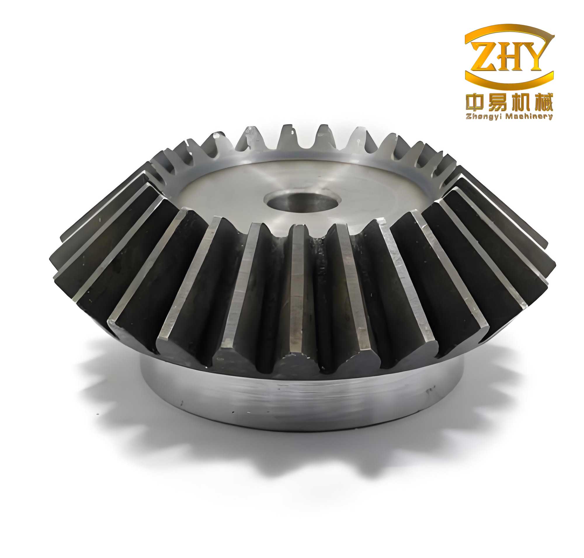
The heart of the dual-steering functionality lies in the bevel gear transmission system. Bevel gears are employed to convert the flipping motion into a simultaneous rotation of the product. Specifically, one bevel gear is attached to the flipping block’s fixed shaft, and another is connected to the rotating block. As the cylinder drives the flip, the bevel gears mesh, causing the rotating block to spin. To achieve a precise 180° rotation, the gear ratio must be 2:1; that is, the gear on the fixed shaft (bevel gear A) has twice the number of teeth as the gear on the rotating block (bevel gear B). This relationship is expressed as: $$ \frac{Z_A}{Z_B} = 2 $$ where $Z_A$ and $Z_B$ are the tooth counts of bevel gear A and bevel gear B, respectively. The use of bevel gears ensures efficient power transmission and compact design, which is crucial for space-constrained automation equipment. To enhance stability, two sets of bearings support the rotating block, minimizing wobble and friction. Additionally, an auxiliary leveling block links the two rotating blocks during assembly, facilitating quick alignment and calibration. This focus on bevel gears underscores their versatility in complex motion control scenarios.
To prevent product displacement during steering, a vacuum suction system is integrated. The rotating block features a central through-hole connected to a vacuum electromagnetic valve via a pipe fitting. When activated, the valve generates negative pressure to hold the product securely. The suction force must exceed the product’s weight to ensure stability. The vacuum force can be calculated using the formula: $$ W = C \times P \times 0.1 \times f $$ where $W$ is the vacuum force in Newtons, $C$ is the effective area of the suction port in cm², $P$ is the vacuum pressure in kPa, and $f$ is a safety factor. For this application, with $C = 0.1256 \, \text{cm}^2$ (based on a small port diameter), $P = -70 \, \text{kPa}$, and $f = 1/8$, the calculation yields: $$ W = 0.1256 \times (-70) \times 0.1 \times \frac{1}{8} = 0.11 \, \text{N} $$ The product weighs 3 g, corresponding to a gravitational force of $0.03 \, \text{N}$ ($F_g = m \cdot g = 0.003 \, \text{kg} \times 9.8 \, \text{m/s}^2 \approx 0.03 \, \text{N}$). Since $W > F_g$, the suction is sufficient. The vacuum valve is mounted proximately on the support frame to reduce response time, enhancing overall efficiency. This approach leverages pneumatic principles for precise product handling.
Precision in the start and end positions is critical for seamless product transfer. To achieve this, I incorporated a buffer and limit system comprising hydraulic dampers and adjustable limit screws. These components absorb impact during flipping and ensure repeatable positioning. Hardened stop pins (50–55 HRC) are installed on the flipping block to interface with the buffers and screws, preventing wear on the main block. This modular design allows easy replacement of pins without disassembling the entire mechanism, saving maintenance time and cost. The buffer force can be modeled using damping equations, such as: $$ F_d = -c \cdot v $$ where $F_d$ is the damping force, $c$ is the damping coefficient, and $v$ is the velocity. This ensures controlled deceleration. Table 2 summarizes key design parameters for the buffer and limit components.
| Component | Function | Specifications | Benefits |
|---|---|---|---|
| Hydraulic Damper | Absorbs kinetic energy during flipping | Adjustable damping force, compact size | Reduces shock, prolongs life |
| Limit Screw | Sets precise stop positions | Thread-adjustable with lock nuts | Ensures positional accuracy |
| Stop Pin | Interfaces with buffer/screw | Hardened steel, replaceable | Minimizes wear on flipping block |
In practice, the steering mechanism operates as follows: First, the product is placed into the rotating block from a previous station. The vacuum suction activates, securing the product. Then, the pneumatic cylinder extends, driving the flipping block through a 90° arc. Simultaneously, the bevel gears engage, causing the rotating block to spin 180°. Upon reaching the end position, the buffers dampen the motion, and limit screws define the final orientation. The vacuum releases, and the product is removed for the next assembly step. This integrated process highlights the synergy between bevel gears, pneumatics, and vacuum technology.
Throughout the design, I emphasized the role of bevel gears in enabling compact, synchronized motions. Bevel gears offer several advantages, including high torque capacity, efficiency at right angles, and durability. In this mechanism, they are critical for translating linear flipping into rotational output. To further optimize performance, factors like gear material, lubrication, and backlash must be considered. For instance, using hardened steel for the bevel gears enhances wear resistance, while proper lubrication reduces noise and friction. The gear meshing condition can be analyzed using the Lewis bending equation for gear teeth: $$ \sigma = \frac{F_t}{b \cdot m \cdot Y} $$ where $\sigma$ is bending stress, $F_t$ is tangential force, $b$ is face width, $m$ is module, and $Y$ is the Lewis form factor. This ensures the bevel gears withstand operational loads.
In conclusion, this dual-steering 180° mechanism demonstrates an effective solution for automated assembly lines, combining flipping and rotation into a single unit. By leveraging bevel gears for motion transmission, pneumatic cylinders for actuation, and vacuum suction for stability, the design meets stringent requirements for precision, reliability, and cost-efficiency. Future optimizations could involve exploring different bevel gear geometries, such as spiral bevel gears for smoother engagement, or integrating sensors for real-time position feedback. The continuous refinement of such mechanisms, with a focus on bevel gears and integrated design, will drive advancements in manufacturing automation, enabling higher throughput and improved product quality.