
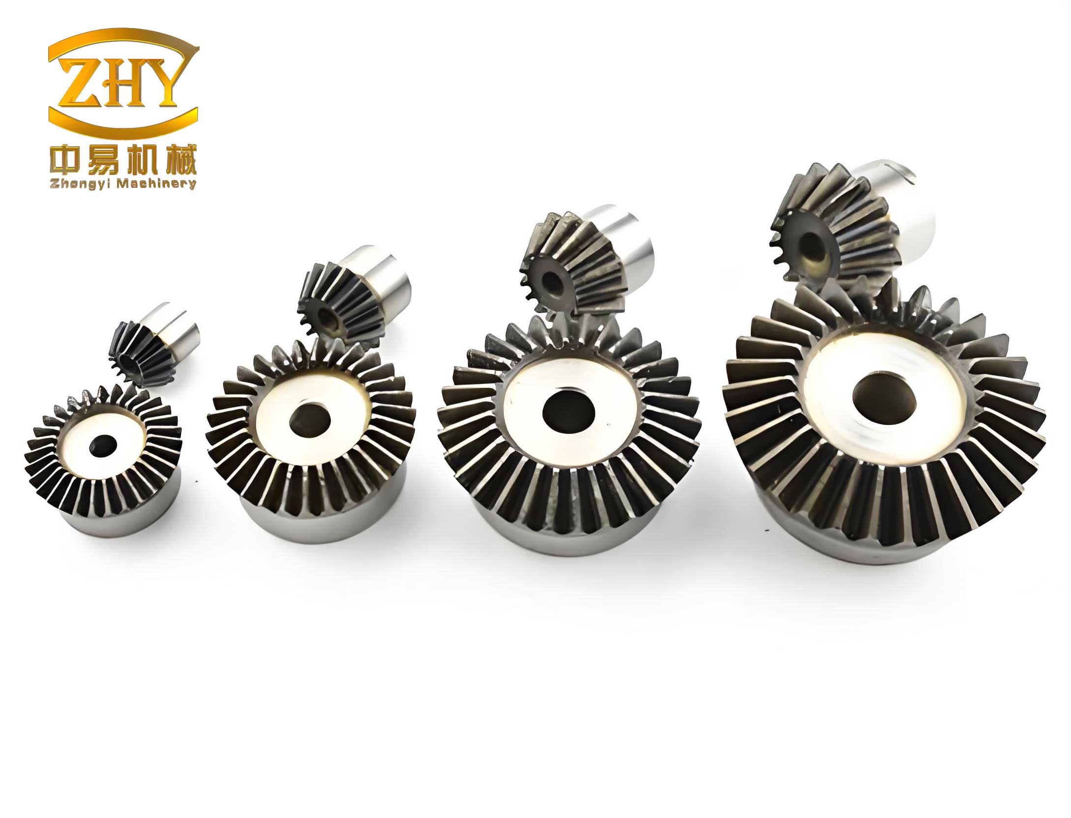
In the field of mechanical power transmission, particularly within demanding applications like aerospace, the reliable design and analysis of bevel gears are paramount. A critical aspect of this process is the accurate assessment of tooth surface contact fatigue strength, which directly predicts resistance to failure modes like pitting and spalling. Engineers worldwide rely on various standards to perform these calculations, and understanding the nuances between them is crucial for correctly interpreting results, especially in an era of global collaboration and software interoperability. This article presents a comprehensive, first-person analysis and comparison of the methodology for calculating the contact fatigue load capacity of bevel gears as defined by two prominent standards: the Chinese Aviation Industry Standard (HB) and the International Organization for Standardization standard (ISO). The goal is to elucidate the foundational differences in formulas, correction factors, and their underlying philosophies, ultimately explaining how these differences manifest in the final calculated safety factors.
The fundamental approach shared by both the HB and ISO standards for rating bevel gears against contact fatigue is the comparison of a calculated contact stress with an allowable contact stress. The core safety condition is expressed identically:
$$ \sigma_{HP} \ge \sigma_H $$
$$ S_H \ge S_{Hmin} $$
Here, $\sigma_{HP}$ is the allowable contact stress, $\sigma_H$ is the calculated contact stress, $S_H$ is the calculated safety factor, and $S_{Hmin}$ is the required minimum safety factor. While the governing inequality is the same, the paths taken by each standard to arrive at $\sigma_H$ and $\sigma_{HP}$ diverge significantly in detail and comprehensiveness. The selection of $S_{Hmin}$ also differs; HB typically links it to a probability of failure (e.g., 1% or 0.1%), whereas ISO provides ranges based on desired reliability levels (general, high, very high). This initial philosophical difference hints at the deeper variations to follow.
Comparative Analysis of Calculated Contact Stress ($\sigma_H$)
Both standards calculate the operational contact stress $\sigma_H$ by starting from a nominal or “basic” contact stress $\sigma_{H0}$ and modifying it with a series of coefficients that account for real-world loading and geometrical conditions. The general form is:
$$ \sigma_H = \sigma_{H0} \cdot K_A \cdot K_V \cdot K_{H\beta} \cdot (\text{other factors}) $$
Where $K_A$ is the application factor, $K_V$ is the dynamic factor, and $K_{H\beta}$ is the face load factor for contact stress. The definition of $\sigma_{H0}$ and the set of “other factors” constitute the primary area of divergence. The table below summarizes the key formulas.
| Parameter | HB Standard | ISO Standard (ISO 10300) |
|---|---|---|
| Calculated Contact Stress | $$ \sigma_H = \sigma_{H0} \sqrt{K_A K_V K_{H\beta}} $$ | $$ \sigma_H = \sigma_{H0} \sqrt{K_A K_V K_{H\alpha} K_{H\beta}} $$ |
| Basic Contact Stress | $$ \sigma_{H0} = Z_H Z_E Z_\epsilon Z_i Z_\rho Z_C \sqrt{\frac{F_{mt}}{d_{v1} b} \frac{u_v + 1}{u_v}} $$ | $$ \sigma_{H0} = Z_{M-B} Z_E Z_H Z_{LS} Z_\beta Z_K \sqrt{\frac{F_{mt}}{d_{v1} b_{m}} \frac{u_v + 1}{u_v}} $$ |
| Nominal Tangential Force | $$ F_{mt} = \frac{2000 \cdot T}{d_m} $$ | $$ F_{mt} = \frac{2000 \cdot T}{d_m} $$ |
Where common symbols are: $F_{mt}$ is the nominal tangential force at the pitch circle midpoint (N), $T$ is torque (Nm), $d_m$ is the mean pitch diameter (mm), $d_{v1}$ is the equivalent virtual cylindrical gear pitch diameter of the pinion (mm), $u_v$ is the equivalent gear ratio, $b$ and $b_m$ are facewidths (mm).
Dissecting the Correction Factors
The juxtaposition of the $\sigma_{H0}$ formulas immediately reveals a different selection of influence factors. A side-by-side comparison categorizing these factors is illuminating.
| Influence Category | HB Standard Factors | ISO Standard Factors |
|---|---|---|
| Load Distribution | $K_{H\beta}$ (Face load factor) | $K_{H\alpha}$ (Transverse load factor), $K_{H\beta}$ (Face load factor) |
| Geometry | $Z_H$ (Zone factor), $Z_\rho$ (Profile curvature factor), $Z_C$ (Crowning factor), $b$ (facewidth) | $Z_H$ (Zone factor), $Z_{M-B}$ (Mid-point zone factor), $Z_\beta$ (Helix angle factor), $b_m$ (length of contact line at mid-point) |
| Material | $Z_E$ (Elasticity factor) | $Z_E$ (Elasticity factor) |
| Contact & Load Sharing | $Z_\epsilon$ (Contact ratio factor), $Z_i$ (Inertia factor) | $Z_{LS}$ (Load sharing factor), $Z_K$ (Bevel gear factor) |
Key Differences in Factor Philosophy:
- Transverse Load Distribution ($K_{H\alpha}$): ISO explicitly includes this factor to account for uneven load sharing between simultaneously engaged tooth pairs due to mesh stiffness variations, pitch deviations, and run-in. HB does not have a direct equivalent, potentially simplifying this complex interaction.
- Geometric Modeling: HB uses factors like $Z_\rho$ and $Z_C$ to adjust stress from the pitch point to the most critical point and for crowning, respectively. ISO uses a mid-point methodology encapsulated in $Z_{M-B}$ and bases the effective contact length $b_m$ on the contact line length at the mid-point of the tooth, modified by the contact ratio and helix angle $Z_\beta$. This represents a different modeling approach for the contact geometry of bevel gears.
- Load Sharing and Inertia: HB’s $Z_i$ factor accounts for load fluctuations when the total contact ratio is low. ISO uses $Z_{LS}$ for load sharing between pairs of teeth and introduces an empirical $Z_K$ factor (often =1) to harmonize stress calculations between cylindrical and bevel gears.
The Critical Difference: Dynamic Factor ($K_V$)
The calculation of the dynamic factor $K_V$ showcases one of the most significant methodological divergences. The HB standard employs a relatively simple, closed-form equation based primarily on pitch line velocity:
$$ K_{V(HB)} = 1 + \frac{14 v_c}{85 – 10u} $$
where $v_c$ is the pitch line velocity (m/s) and $u$ is the gear ratio.
In stark contrast, the ISO standard adopts a much more detailed, physics-based approach that considers the gear system’s dynamic response. It first calculates a dimensionless speed parameter $N$, which is the ratio of the pinion’s rotational frequency to the natural frequency of the gear mesh. Based on this ratio, it selects one of three formulas for three distinct resonance regions:
- Sub-critical Range ($N \leq 0.75$): $$ K_{V(ISO)} = 1 + \frac{b_{eff} f_{pe} c’}{F_{mt} K_A} (C_{v1,2} + C_{v3}) $$
- Main Resonance Range ($0.75 < N \leq 1.25$): $$ K_{V(ISO)} = 1 + \frac{b_{eff} f_{pe} c’}{F_{mt} K_A} (C_{v1,2} + C_{v4} + 1) $$
- Super-critical Range ($N \geq 1.5$): $$ K_{V(ISO)} = 1 + \frac{b_{eff} f_{pe} c’}{F_{mt} K_A} (C_{v5,6} + C_{v7}) $$
Here, $b_{eff}$ is the effective facewidth, $f_{pe}$ is an equivalent misalignment, $c’$ is the tooth stiffness, and the $C_v$ coefficients are functions of the speed parameter $N$, damping, and stiffness. This model explicitly accounts for resonant magnification, making it far more sensitive to the system’s dynamic properties than the HB formula.
Comparative Analysis of Allowable Contact Stress ($\sigma_{HP}$)
The allowable contact stress for bevel gears is derived from the material’s permissible fatigue limit, reduced by a safety factor and modified by coefficients accounting for life, operating conditions, and size effects. The framework is similar, but the set of modifying coefficients again differs markedly.
| Parameter | HB Standard | ISO Standard |
|---|---|---|
| Allowable Contact Stress | $$ \sigma_{HP} = \frac{\sigma_{Hlim}}{S_{Hmin}} Z_N Z_0 $$ | $$ \sigma_{HP} = \frac{\sigma_{Hlim}}{S_{Hmin}} Z_{NT} Z_X Z_L Z_R Z_V Z_W $$ |
Where $\sigma_{Hlim}$ is the contact fatigue limit of the material.
| Influence Category | HB Standard Factors | ISO Standard Factors |
|---|---|---|
| Life | $Z_N$ (Life factor) | $Z_{NT}$ (Life factor for pitting) |
| Operating Conditions | $Z_0$ (Temperature factor) | $Z_V$ (Speed factor), $Z_L$ (Lubricant factor), $Z_W$ (Work hardening factor) |
| Surface Condition | — | $Z_R$ (Roughness factor) |
| Size Effect | — | $Z_X$ (Size factor) |
Key Differences in Allowable Stress Factors:
- Scope of Operational Effects: HB primarily modifies the fatigue limit based on required life ($Z_N$) and bulk operating temperature ($Z_0$). ISO incorporates a much wider array: lubricant film formation ($Z_L$), surface roughness ($Z_R$), sliding speed effects ($Z_V$), and the beneficial work hardening from mating a hardened pinion with a softer gear ($Z_W$).
- Statistical and Size Effects: ISO includes a size factor $Z_X$ to account for the statistically observed decrease in fatigue strength with increasing component size, a factor not present in the HB standard for bevel gears.
This comprehensive suite of factors in the ISO standard generally allows for a more refined and often higher $\sigma_{HP}$ if conditions are favorable (good lubrication, smooth surfaces, appropriate hardness combination), reflecting a more nuanced understanding of the tribological and statistical aspects of gear fatigue.
Case Study Calculation and Result Synthesis
To concretely illustrate the impact of these methodological differences, let’s consider a pair of spiral bevel gears with representative parameters.
| Parameter | Pinion | Gear |
|---|---|---|
| Number of Teeth | 36 | 49 |
| Module (mm) | 4 | |
| Pressure Angle (°) | 20 | |
| Helix Angle (°) | 35 | |
| Facewidth (mm) | 22 | |
| Surface Roughness Ra (μm) | 0.4 | |
| Transmitted Power (kW) | 1250 | |
| Rotational Speed (rpm) | 5172 | 3800 |
Using the same input data, calculations were performed according to both the HB and ISO (10300) methodologies. The summary of key results is presented below.
| Result Parameter | HB Standard | ISO Standard |
|---|---|---|
| Basic Contact Stress, $\sigma_{H0}$ (MPa) | 2948.2 | 1357.3 |
| Dynamic Factor, $K_V$ | 1.00 | 1.94 |
| Calculated Contact Stress, $\sigma_H$ (MPa) | 2613.5 | 2589.0 |
| Allowable Contact Stress, $\sigma_{HP}$ (MPa) | 1331.7 | 1535.3 |
| Calculated Safety Factor, $S_H$ | 0.51 ($\sigma_{HP}/\sigma_H$) | 0.59 ($\sigma_{HP}/\sigma_H$) |
Analysis of the Discrepancies:
- Basic Contact Stress ($\sigma_{H0}$): The ISO value is less than half of the HB value. This massive difference stems primarily from the different geometric modeling approaches ($Z_{M-B}$, $b_m$, $Z_\beta$ vs. $Z_\rho$, $Z_C$) and the inclusion of $Z_{LS}$ and $Z_K$ in ISO.
- Dynamic Factor ($K_V$): The ISO standard predicts a significant dynamic overload ($K_V=1.94$), while HB calculates none ($K_V=1.00$) for this case. This is a direct consequence of ISO’s resonant dynamic model, which likely placed this high-speed gear pair in a resonant or near-resonant condition.
- Final Calculated Stress ($\sigma_H$): Despite the vastly different starting points for $\sigma_{H0}$, the subsequent application of correction factors—especially the large $K_V$ in ISO—brings the two final $\sigma_H$ values remarkably close (2613.5 vs. 2589.0 MPa). This convergence is somewhat coincidental for this specific case but highlights how differences in one part of the calculation (geometry) can be offset by differences in another (dynamics).
- Allowable Stress ($\sigma_{HP}$): The ISO allowable stress is approximately 15% higher. This is due to the positive influence of its additional factors like the lubricant factor $Z_L$, roughness factor $Z_R$, and speed factor $Z_V$, which collectively outweigh the effect of the size factor $Z_X$.
- Safety Factor: Both standards indicate a safety factor below 1.0 for the chosen $S_{Hmin}$, signaling a design insufficient against pitting. However, the ISO calculation yields a slightly less severe prediction (0.59 vs. 0.51).
A closer look at the calculated values of individual factors further clarifies the compositional differences.
| Factor Type | HB Standard (Value) | ISO Standard (Value) |
|---|---|---|
| Zone Factor ($Z_H$, $Z_{M-B}$) | $Z_H = 2.13$ | $Z_H = 2.13$, $Z_{M-B} = 1.001$ |
| Contact Geometry / Sharing | $Z_\rho=0.994$, $Z_C=1.304$, $Z_i=1.029$ | $Z_{LS}=1.00$, $Z_K=0.8$, $Z_\beta=0.905$ |
| Life Factor | $Z_N = 0.833$ | $Z_{NT} = 1.038$ |
| Surface & Lubrication | — | $Z_R=1.00$, $Z_L=1.02$, $Z_V=1.00$ |
Conclusion and Final Remarks
This detailed comparative analysis between the HB and ISO standards for calculating the contact fatigue strength of bevel gears reveals fundamental differences in engineering philosophy and modeling granularity. The ISO 10300 standard demonstrates a more comprehensive and physically detailed approach. It explicitly accounts for a wider range of phenomena: transverse load sharing between teeth ($K_{H\alpha}$), system dynamics including resonance ($K_V$), detailed mid-point contact geometry, and the influence of lubrication, roughness, and size effects on the permissible fatigue limit.
The key practical findings are:
- The ISO standard’s basic contact stress $\sigma_{H0}$ for bevel gears is typically calculated to be significantly lower than that from the HB standard, due to different geometric modeling and stress reference points.
- The ISO dynamic factor $K_V$ can be substantially different (often larger) as it captures resonant behavior neglected by the simpler HB formula.
- These differences can offset each other, sometimes leading to comparable final calculated stresses $\sigma_H$, but this is not a rule and depends heavily on the specific gear geometry and operating conditions.
- The ISO allowable contact stress $\sigma_{HP}$ tends to be higher for well-lubricated, smooth bevel gears due to the beneficial factors $Z_L$, $Z_R$, and $Z_W$.
- Therefore, a direct numerical comparison of safety factors or absolute stress values between software or reports using different standards is meaningless without understanding these underlying methodological divergences. An apparently “higher stress” from an HB-based calculation does not necessarily imply a less safe design compared to an ISO-based one, and vice-versa.
For engineers working with bevel gears in international contexts, especially when using commercial software rooted in different standards, this understanding is critical. It emphasizes the necessity of knowing which standard is being applied as the basis for calculation and of performing comparative assessments within the consistent framework of a single standard. The choice between standards like HB and ISO often depends on regulatory requirements, historical practice, or the desired level of analytical detail, but appreciating their differences is essential for accurate technical communication and reliable gear design validation.