
In industrial applications, screw gears, commonly referred to as worm gear reducers, are extensively utilized due to their high reduction ratios and smooth transmission characteristics. As a researcher in mechanical engineering, I have focused on developing online monitoring techniques for these critical components. Traditional methods for assessing wear in screw gears often require shutdowns, leading to prolonged maintenance cycles. This article presents a vibration-based approach that enables real-time condition monitoring of screw gears, leveraging signal processing techniques to analyze wear states without interrupting operations. Through field testing, I have validated the effectiveness of this method, which offers a practical solution for enhancing the reliability of screw gear systems in manufacturing environments.
Screw gears, consisting of a worm and a worm wheel, are integral to many mechanical drives, especially where large speed reductions are needed. Their ability to provide self-locking and compact design makes them indispensable in industries such as automotive, aerospace, and heavy machinery. However, screw gears are prone to failures like surface pitting, wear, and scuffing due to high sliding velocities and frictional heat generation. Monitoring these conditions is crucial to prevent unexpected downtime. In my work, I explore how vibration signals can be harnessed to detect early signs of wear in screw gears, emphasizing the importance of online measurement for proactive maintenance.
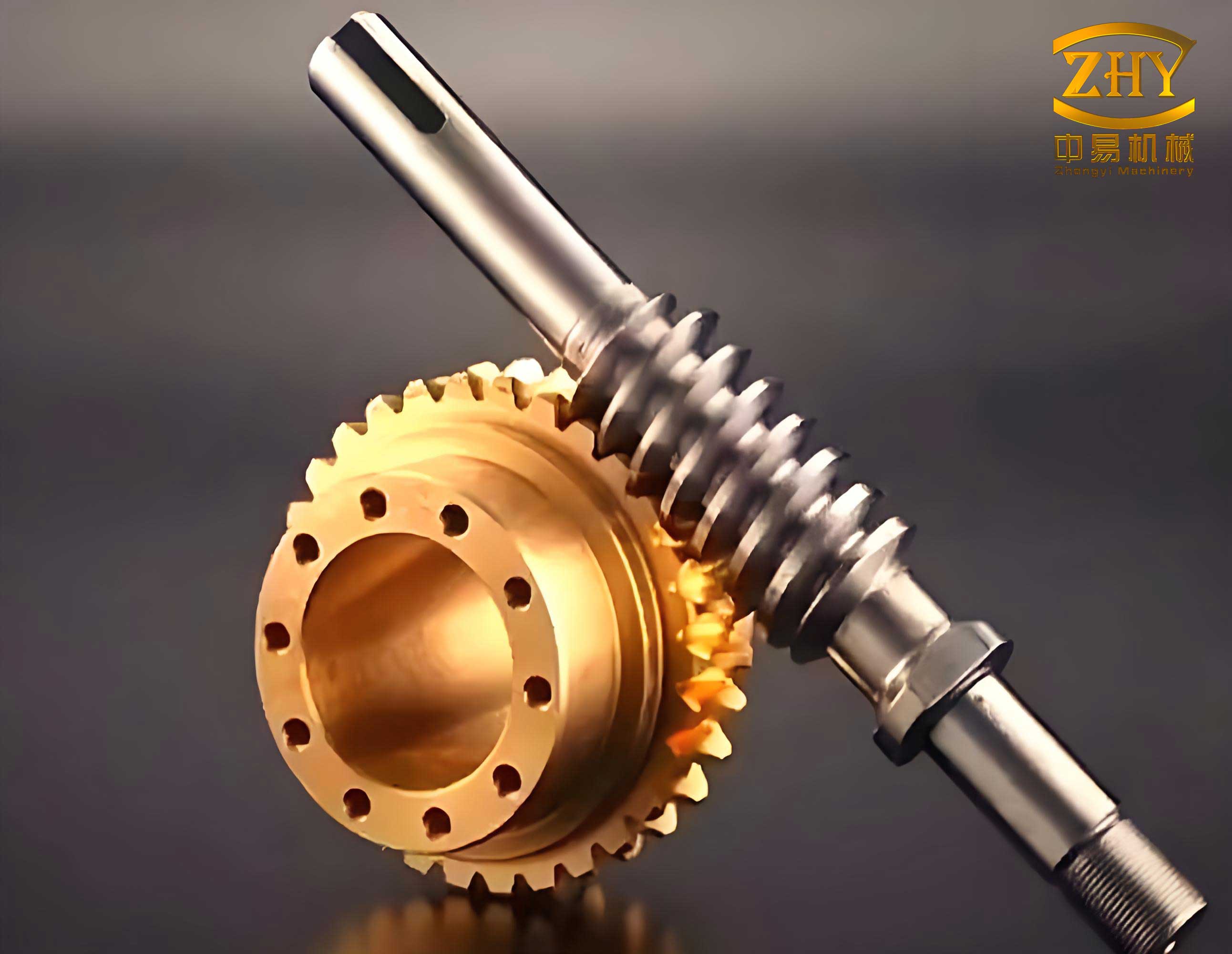
The failure modes of screw gears primarily involve surface degradation. During operation, the interaction between the worm and worm wheel generates significant forces, which can be decomposed into axial, radial, and circumferential components. For instance, the normal force \( F_n \) acting on the screw gears can be broken down as follows:
$$ F_{x1} = F_n \sin(\alpha) \quad \text{(axial force on worm)} $$
$$ F_{t1} = F_n \cos(\alpha) \cos(\beta) \quad \text{(circumferential force on worm)} $$
$$ F_{r1} = F_n \cos(\alpha) \sin(\beta) \quad \text{(radial force on worm)} $$
where \( \alpha \) is the pressure angle and \( \beta \) is the lead angle. Similarly, forces on the worm wheel are derived. When defects arise on the tooth surfaces of screw gears, these force components fluctuate, exciting vibrations in the gearbox housing. By measuring these vibrations, I can infer the health state of the screw gears. This forms the basis of my vibration monitoring methodology, which targets the modulation of resonant frequencies in the transmission path.
To analyze these vibrations, I employ a harmonic frequency measurement approach. Since screw gears operate smoothly with low vibration amplitudes, direct measurement of low-frequency signals is challenging due to attenuation. Instead, I focus on the resonant frequency band of the transmission path, where signal transmission is most efficient. The vibration signals in this band are modulated by the internal low-frequency dynamics of the screw gears. By applying bandpass filtering and envelope demodulation, I extract these modulating signals for further analysis. This process involves several key steps, as summarized in the table below:
| Step | Description | Key Formula |
|---|---|---|
| 1. Signal Acquisition | Measure vibration signals from screw gear housing using accelerometers. | \( x(t) = a(t) \cos(2\pi f_0 t + \phi(t)) \) |
| 2. Bandpass Filtering | Isolate resonant frequency band (e.g., 70-90 Hz) to reduce noise. | \( H(f) = \frac{1}{1 + j(Q(\frac{f}{f_r} – \frac{f_r}{f}))} \) |
| 3. Hilbert Transform | Compute analytic signal for envelope extraction. | \( x'(t) = \frac{1}{\pi} \int_{-\infty}^{\infty} \frac{x(\tau)}{t – \tau} d\tau \) |
| 4. Envelope Demodulation | Obtain amplitude modulation signal. | \( a(t) = \sqrt{x^2(t) + x’^2(t)} \) |
| 5. Signal Reconstruction | Separate worm and wheel components via frequency-domain purification. | \( y(t) = \sum_{i} A_i \sin(2\pi f_i t + \phi_i) \) |
The Hilbert transform is central to this analysis. For a real signal \( x(t) \), the Hilbert transform \( x'(t) \) is defined as:
$$ x'(t) = \frac{1}{\pi} \int_{-\infty}^{\infty} \frac{x(\tau)}{t – \tau} d\tau $$
This operation acts as a 90-degree phase shifter, allowing the construction of an analytic signal \( q(t) = x(t) + i x'(t) \). The magnitude of \( q(t) \) gives the envelope \( a(t) \), which encapsulates the low-frequency modulations related to screw gear wear. For a narrowband signal \( x(t) = a(t) \cos(2\pi f_0 t + \phi(t)) \), the envelope is derived as:
$$ a(t) = |q(t)| = \sqrt{x^2(t) + x’^2(t)} $$
This demodulated signal contains contributions from both the worm and worm wheel components of the screw gears. To separate them, I use a reconstruction technique based on time-domain averaging equivalents. Given the large reduction ratio of screw gears, the worm rotates multiple times per wheel revolution. Thus, worm-related vibrations appear as periodic signals at the worm’s rotational frequency and its harmonics, while wheel-related vibrations are of lower frequency. By reconstructing the signal from its fundamental and harmonic components, I isolate the worm’s contribution. The remaining signal reflects the wheel’s condition.
The reconstruction process involves precise calculation of amplitudes, phases, and frequencies at the worm’s rotational harmonics. Let the demodulated signal be \( x(n) \) for \( n = 0, 1, 2, \ldots \). I segment it into \( N \) periods of length \( M \), corresponding to the worm’s rotation period. The averaged signal \( y(n) \) is:
$$ y(k) = \frac{1}{N} \sum_{i=0}^{N-1} x(k – iM) $$
In the frequency domain, this averaging acts as a comb filter with transfer function:
$$ H(z) = \frac{Y(z)}{X(z)} = \frac{1}{N} \frac{1 – z^{-NM}}{1 – z^{-M}} $$
Its frequency response is:
$$ H(e^{j\omega \Delta t}) = \frac{1}{N} \left| \frac{1 – e^{-j\pi N \omega / \omega_0}}{1 – e^{-j2\pi \omega / \omega_0}} \right| $$
where \( \omega_0 \) is the fundamental frequency. At integer multiples of \( \omega_0 \), the filter gain is unity, preserving the harmonic components. Through this, I reconstruct the worm’s vibration signal as:
$$ x_{\text{worm}}(t) = \sum_{i=1}^{K} A_i \sin(2\pi f_i t + \phi_i) $$
where \( f_i \) are the worm’s rotational harmonics. The residual signal \( x_{\text{residual}}(t) = a(t) – x_{\text{worm}}(t) \) represents the worm wheel’s vibrations. This separation enables independent analysis of each component in screw gears, facilitating targeted wear assessment.
In field tests, I applied this method to both new and old screw gear reducers. The reducers had single-start worms with center distances of 120 mm and module of 5 mm, but different reduction ratios (38 and 29) and structural variations (e.g., reinforcement ribs). Vibration sensors were mounted near the worm and worm wheel bearings. Data acquisition parameters were adjusted based on operational speeds, as shown in the table below:
| Reducer Type | Sampling Frequency (Hz) | Filter Band (Hz) | Worm Speed (Hz) | Data Length |
|---|---|---|---|---|
| Old Screw Gears | 200 | 70.1–80.1 | 0.52 | 6144 |
| New Screw Gears | 400 | 80.3–90.2 | 0.75 | 6144 |
After bandpass filtering and envelope demodulation, I obtained modulation signals. For the old screw gears, the worm component exhibited impulse-like sequences at the worm’s rotational period, indicating wear-induced clearance increases. In contrast, the new screw gears showed near-sinusoidal signals with minor high-frequency oscillations, suggesting proper meshing with minimal wear. The reconstructed signals clearly distinguished these states, validating the method’s capability for online monitoring of screw gears.
To quantify the results, I performed spectral analysis on the demodulated signals. The table below summarizes key frequency components and their amplitudes for both reducers, highlighting differences attributable to wear in screw gears:
| Frequency Component | Old Screw Gears Amplitude (mV) | New Screw Gears Amplitude (mV) | Interpretation |
|---|---|---|---|
| Worm Rotational Frequency (f_w) | 12.5 | 8.2 | Higher amplitude indicates wear |
| 2× f_w | 6.3 | 3.1 | Harmonics reflect nonlinearities |
| 3× f_w | 3.8 | 1.5 | Diminishing with wear |
| Wheel Meshing Frequency | 0.18 | 0.05 | Low-frequency modulations from wheel |
The effectiveness of this vibration-based approach stems from its ability to leverage the unique dynamics of screw gears. By focusing on resonant modulation, I overcome the limitations of low-frequency signal attenuation. The Hilbert transform and reconstruction techniques provide a robust framework for decomposing complex vibrations into interpretable components. This is particularly valuable for screw gears, where traditional oil analysis methods are offline and costly. My method enables continuous monitoring, reducing downtime and maintenance costs for industries reliant on screw gear systems.
Further mathematical elaboration can enhance understanding. Consider the vibration signal \( x(t) \) as a sum of modulated components:
$$ x(t) = \sum_{k} a_k(t) \cos(2\pi f_k t + \phi_k(t)) $$
For screw gears, the dominant modulations occur at frequencies related to the worm’s rotation. The envelope \( a(t) \) can be modeled as:
$$ a(t) = A_0 + \sum_{m} B_m \cos(2\pi f_m t + \theta_m) $$
where \( f_m \) are modulation frequencies from wear processes. By applying Fourier analysis, I extract these frequencies to assess wear severity. For instance, increased amplitude at \( f_w \) correlates with worm wear, while sidebands around harmonics indicate wheel defects. This frequency-domain insight complements the time-domain reconstruction, offering a comprehensive view of screw gear health.
In practice, implementing this method requires careful calibration of sensor positions and filter settings. The resonant frequency band must be identified experimentally for each screw gear setup. I recommend using accelerometers with high sensitivity in the 50–200 Hz range, typical for screw gear vibrations. Data processing can be automated using algorithms implemented in software like MATLAB or Python, enabling real-time monitoring systems. The table below outlines a proposed workflow for online condition monitoring of screw gears:
| Stage | Action | Tools/Parameters |
|---|---|---|
| 1. Installation | Mount sensors on gearbox near worm and wheel. | Accelerometers, data acquisition system |
| 2. Calibration | Determine resonant band via impact testing. | Frequency analyzer, hammer test |
| 3. Data Collection | Acquire vibration signals during operation. | Sampling rate ≥ 500 Hz, duration 10+ seconds |
| 4. Signal Processing | Apply bandpass filter and Hilbert transform. | Digital filters, analytic signal computation |
| 5. Analysis | Reconstruct worm and wheel signals; compare to baselines. | FFT, envelope analysis, threshold detection |
| 6. Alerting | Trigger alarms for abnormal wear indicators. | Automated reporting, maintenance scheduling |
The advantages of this vibration-based method are manifold. It provides a non-intrusive, online solution for monitoring screw gears, reducing the need for disruptive inspections. By early detection of wear, it prevents catastrophic failures and extends the lifespan of screw gear systems. Moreover, the signal separation technique allows pinpointing whether issues originate from the worm or wheel, guiding targeted repairs. This is especially beneficial for screw gears used in critical applications like conveyor systems or robotic arms, where reliability is paramount.
In conclusion, my research demonstrates that vibration analysis is a powerful tool for condition monitoring of screw gears. Through harmonic measurement, envelope demodulation, and signal reconstruction, I have developed a method that effectively separates worm and wheel wear states. Field tests confirm its practicality and accuracy. Future work could integrate machine learning algorithms to predict remaining useful life of screw gears based on vibration trends. Additionally, expanding this approach to other gear types, such as helical or bevel gears, could broaden its industrial impact. For now, this method offers a reliable, cost-effective way to enhance the maintenance of screw gears, ensuring smoother operations and reduced downtime in various sectors.
To further illustrate the mathematical foundations, consider the dynamics of screw gears in terms of force variations. The normal force \( F_n \) changes with wear, affecting vibration amplitudes. A simplified model relates wear depth \( d \) to force modulation:
$$ \Delta F_n = k \cdot d \cdot \sin(2\pi f_m t) $$
where \( k \) is a stiffness constant and \( f_m \) is the modulation frequency. This force variation excites the housing vibration \( v(t) \), which can be expressed as:
$$ v(t) = h(t) * \Delta F_n(t) $$
with \( h(t) \) as the impulse response of the housing. In frequency domain, this becomes:
$$ V(f) = H(f) \cdot \Delta F_n(f) $$
By analyzing \( V(f) \) in the resonant band, I infer \( \Delta F_n(f) \) and thus wear conditions. This convolution model underscores the importance of transfer path analysis in vibration monitoring for screw gears.
Another aspect is the effect of lubrication on screw gear vibrations. Poor lubrication increases friction, altering vibration signatures. I can incorporate this by modeling the damping ratio \( \zeta \) in the system:
$$ \ddot{v}(t) + 2\zeta \omega_n \dot{v}(t) + \omega_n^2 v(t) = F(t) $$
where \( \omega_n \) is the natural frequency. Changes in \( \zeta \) due to lubrication state affect vibration amplitudes and frequencies, providing additional diagnostic information for screw gears. Monitoring these parameters alongside wear indicators offers a holistic view of gear health.
In summary, the vibration-based method I propose leverages advanced signal processing to tackle the challenges of monitoring screw gears. By combining theoretical insights with practical testing, it paves the way for smarter maintenance strategies. As industries increasingly adopt predictive maintenance, techniques like this will become essential for optimizing the performance and longevity of screw gear systems.