
The pursuit of high-precision, quiet-running gears in mass production necessitates efficient finishing processes. Among these, gear shaving stands out as a remarkably productive and effective method. As a finishing technique, gear shaving is widely employed in the automotive, tractor, and machine tool industries due to its high production rate, excellent final gear quality, good tool longevity, and the relative simplicity of the machine tools involved. The process is capable of enhancing gear accuracy by 1 to 2 grades, typically achieving a final quality of AGMA 5 to 7 or ISO 6 to 8, with surface roughness values (Ra) ranging from 1.25 to 0.32 μm. My focus here is to provide a comprehensive, first-person perspective on the intricacies of gear shaving, delving into the sources and transformation of errors, the critical necessity and methodology for cutter profile correction, and the quantifiable capabilities of the process, all supported by analytical models and empirical data.
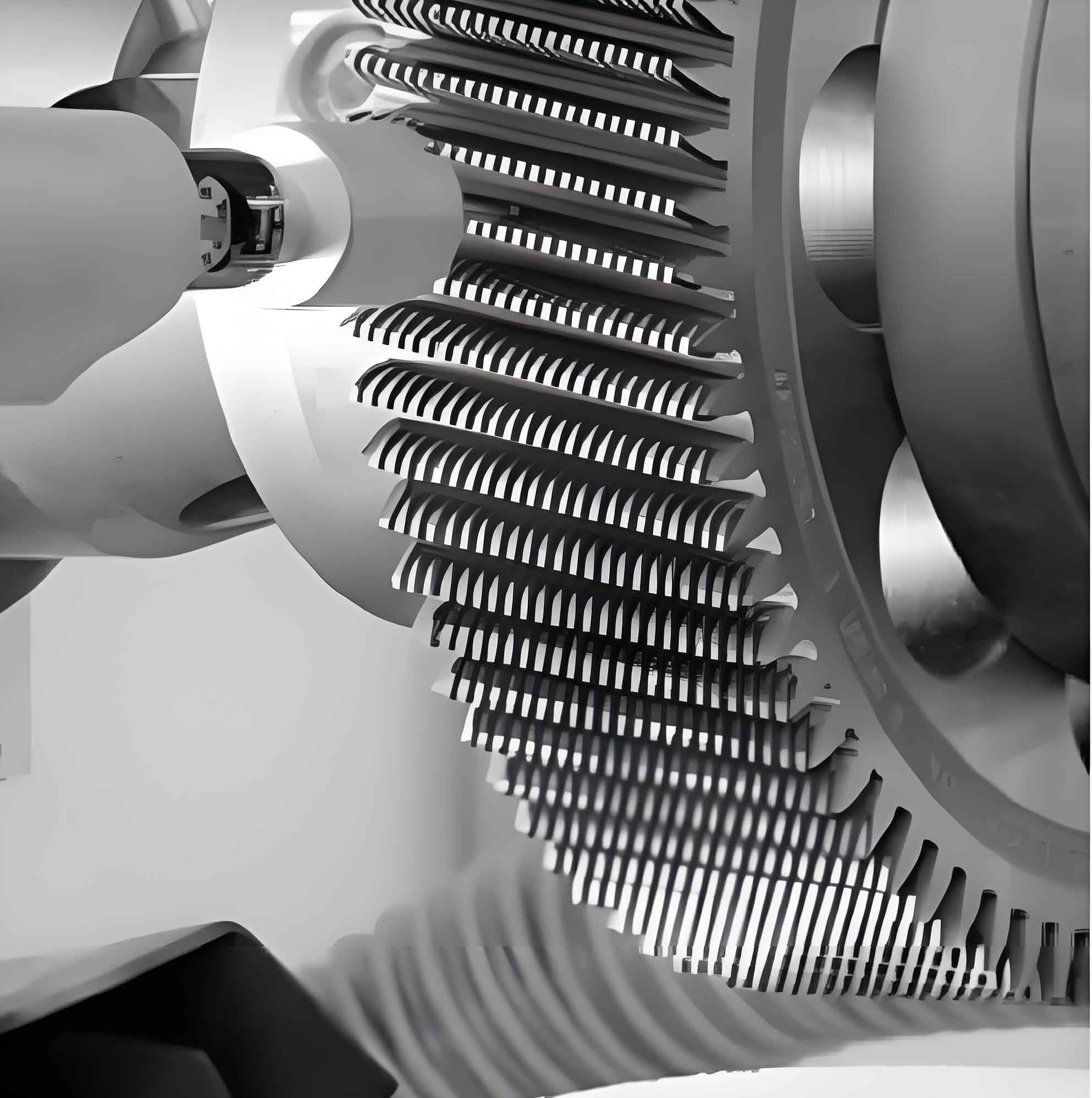
The fundamental principle of gear shaving is based on the crossed-axes meshing of helical gears. The shaving cutter, a high-precision helical gear with gashes cut across its teeth to form cutting edges, is meshed with the workpiece gear at a crossed-axes angle. This setup creates a point contact that moves across the tooth flank as the workpiece is driven in tight mesh with the rotating cutter. The axial reciprocation (or alternate diagonal, underpass, etc.) of the workpiece or cutter provides the relative sliding motion necessary for the cutting action. This sliding motion, combined with a controlled radial feed, removes a thin layer of material, typically 0.01 to 0.06 mm, from the tooth flanks. The kinematics of this process are crucial for understanding its error correction behavior. The continuous point contact and the fact that the cutter teeth do not have a fixed, permanent pairing with specific workpiece teeth allow the process to smooth out minor irregularities. The sliding action effectively erases the tool marks from the pre-shaving operation (usually hobbing or shaping) and can improve tooth profile (form) and lead (alignment) accuracy.
However, it is imperative to understand that gear shaving is not a magical solution for all gear inaccuracies. Its corrective power has well-defined limits. Since the process relies on a free, force-closed meshing action rather than a rigid, kinematic linkage (like in gear grinding with a worm-shaped wheel), it cannot correct systematic geometric mismatches that are equal and opposite on the left and right flanks. The most significant limitation is its inability to reduce pitch cumulative error (or single pitch deviation accumulation over a full rotation), as this error is fundamentally related to the geometric relationship of all tooth positions around the gear’s axis—a relationship the free-meshing shaving process does not forcibly re-establish. The final quality from a gear shaving operation is heavily dependent on the quality of the pre-shaved workpiece. As a general rule, the pre-shave gear quality should be no more than one accuracy grade below the desired final grade, and it must possess minimal pitch cumulative error to begin with. The corrective capability of gear shaving for various error types is summarized in the table below, which provides practical data limits for both spur and helical gears.
| Gear Error Type | Permissible Error Before Shaving (mm) | Typical Achievable Error After Shaving (mm) | Primary Influencing Factors for Residual Error |
|---|---|---|---|
| Tooth Profile Error | 0.02 – 0.07 | 0.008 – 0.02 | Cutter profile error, excessive stock allowance at tip/root, workpiece/cutter radial runout. |
| Radial Composite Deviation (Single Revolution) | 0.06 – 0.08 | 0.02 – 0.04 | Workpiece eccentricity, clamping errors, pre-shave runout. |
| Radial Composite Deviation (Tooth-to-Tooth) | 0.02 – 0.03 | 0.01 – 0.02 | Pre-shave single pitch error, cutter pitch error. |
| Runout (Radial) | 0.05 – 0.07 | 0.02 – 0.03 | Pre-shave runout, workpiece clamping eccentricity. |
| Lead Error (over 25 mm) | 0.02 – 0.03 | 0.007 – 0.015 | Machine alignment (slideway vs. cutter axis), pre-shave lead error, workpiece mounting tilt. |
| Single Pitch Deviation | 0.02 – 0.04 | 0.008 – 0.015 | Pre-shave pitch errors, cutter pitch accuracy. |
Note: The upper limit in the ranges typically applies to spur gears, while the lower limit is more applicable to helical gears. Helical gears generally achieve higher final accuracy under comparable conditions.
A detailed analysis of error sources is critical for process control. The table above hints at the causes, but let’s expand. Profile and base pitch errors primarily stem from inaccuracies in the shaving cutter itself or excessive errors in the pre-shaved workpiece. An uneven stock distribution, with too much material at the root or tip, can also lead to profile distortion as the cutter’s cutting pressure varies across the flank. Pitch errors are largely inherited from the pre-shave state, particularly if significant radial runout is present. As stated, pitch cumulative error is non-correctable; its presence post-shaving is a direct reflection of pre-shave quality or induced by eccentric mounting of either the workpiece or the cutter on the machine. Lead errors are most often a function of machine tool geometry. Misalignment between the axial travel direction and the theoretical plane of action, or an incorrect setup of the crossed-axes angle ($\Sigma$), will directly imprint a lead error. Furthermore, a workpiece mounting that is not square to its axis of rotation, or excessive clearance in its arbor, can introduce wobble that translates into lead variation.
The physics of the crossed-axes meshing contact in gear shaving introduces a unique and critical phenomenon that necessitates proactive correction of the shaving cutter’s profile. If a shaving cutter with a theoretically perfect involute profile is used, the finished workpiece tooth profile will often exhibit a slight concavity in the middle region of the active flank. This “mid-point depression” or “hollow” can range from 0.01 to 0.03 mm and spans approximately the central 50% of the functional profile length. This is not a processing error but a fundamental consequence of the contact mechanics.
During the meshing cycle of a crossed-axes helical gear pair (cutter and workpiece), contact occurs at a theoretical point. However, due to elastic deformation under cutting loads and the geometry of engagement, the contact zone is elliptical. More importantly, the number of tooth pairs in simultaneous contact fluctuates. Analysis of the contact path reveals distinct zones: near the root and tip regions, two tooth pairs are often in contact (“two-point contact”), sharing the load. In the middle section of the flank, only one tooth pair carries the full load (“single-point contact”). This transition and the resulting variation in specific pressure (force per unit area) across the flank lead to non-uniform material removal. The higher specific pressure in the single-contact zone can cause increased deflection and/or a higher effective cutting pressure, resulting in more material being removed from this area than from the two-contact zones at the ends. The relationship for the theoretical contact point location can be derived from the gear geometry. The pressure angle at any radius $r$ on the involute is given by:
$$\phi_r = \arccos\left(\frac{r_b}{r}\right)$$
where $r_b$ is the base radius. The path of contact in a parallel-axis mesh is a straight line. In crossed-axes gear shaving, this transforms into a complex spatial curve. The instantaneous removal rate could be conceptually modeled as proportional to sliding velocity, contact pressure, and time of contact, leading to a non-linear material removal function along the profile.
Therefore, to produce a workpiece with a straight or optimally modified flank, the shaving cutter profile must be pre-corrected to compensate for this inherent process deflection/pressure effect. This correction is not merely for the “mid-point depression”; it is also used to impart deliberate modifications to the workpiece, such as tip and root relief, to enhance meshing performance, reduce noise, and accommodate potential misalignment or thermal distortion in the final application. The process of determining the correct shaving cutter modification profile is iterative and empirical, typically following these steps:
- Initial Trial: A shaving cutter is manufactured or re-sharpened to a standard, theoretically correct involute profile.
- Test Shaving: This cutter is used to shave a sample workpiece under controlled, standardized production conditions (feeds, speeds, axis angle).
- Workpiece Measurement: The tooth profile of the shaved workpiece is meticulously measured using a high-precision gear analyzer or coordinate measuring machine (CMM). The deviation from the desired profile (e.g., the “hollow”) is recorded as a curve $d_w(h)$, where $h$ is the roll distance or position along the profile.
- Establishing the Correspondence: This is the most critical analytical step. A kinematic model of the gear shaving process is used to map every point on the workpiece profile $h_w$ to its corresponding generating point on the cutter profile $h_c$. The relationship is governed by the basic gear meshing equation and the crossed-axes geometry. A simplified expression for the roll distance relationship involves the transverse pressure angles and helix angles:
$$h_w \approx h_c \cdot \frac{\cos\beta_b_w}{\cos\beta_b_c}$$
where $\beta_b$ is the base helix angle for workpiece (w) and cutter (c). The actual model must account for the axial stroke. The measured workpiece error $d_w(h_w)$ is then translated into a required compensatory error on the cutter $d_c(h_c)$. - Iterative Correction: The cutter is then re-ground with a profile that is the inverse of the required compensation—effectively, if the workpiece was hollow by $+X$, the cutter profile is ground with a corresponding “bump” of $-K \cdot X$ (where $K$ is a factor accounting for process stiffness and other effects, often close to 1 for a first iteration). This modified cutter is used for another test shaving, and the workpiece is measured again. The cycle (steps 2-5) is repeated until the workpiece profile meets the specified target. The final modification curve for the shaving cutter is thus defined and documented for future re-sharpening.
This empirical approach can be enhanced by numerical simulation. The material removal in gear shaving can be modeled by integrating the cutting action along the contact path. A simplified volumetric removal model at a point on the workpiece flank could be expressed as:
$$\Delta V_w \propto \int_{t_{in}}^{t_{out}} v_s(t) \cdot P_c(t) \, dt$$
where $v_s(t)$ is the instantaneous sliding velocity, $P_c(t)$ is the contact pressure, and the integration is over the time the cutter tooth pair is in contact with that workpiece point. By simulating this process with an initially perfect cutter, the mid-point depression effect can be predicted, and an inverse-calculated corrective cutter profile can be generated, reducing the number of physical trial iterations.
| Process Parameter | Typical Range / Setting | Primary Effect on Error Correction | Risk if Improperly Set |
|---|---|---|---|
| Crossed-Axes Angle ($\Sigma$) | 10° – 15° | Determines sliding velocity ratio. Affects cutting efficiency, finish, and heat generation. | Too low: Poor cutting action. Too high: Increased radial force, potential chatter, tooth form distortion. |
| Axial Feed Rate | 0.05 – 0.25 mm/workpiece rev. | Controls productivity and chip load per cutter tooth. Finer feeds improve surface finish. | Too high: Poor surface finish, excessive cutter wear, profile errors. Too low: Reduced productivity, glazing. |
| Radial Infeed | 0.02 – 0.06 mm total (applied in stages) | Directly sets final size and stock removal. Must be synchronized with axial stroke. | Excessive single-pass infeed: Cutter overload, profile errors, poor finish. Inadequate infeed: Failure to correct pre-shave errors. |
| Cutter Speed (Workpiece RPM) | 100 – 300 rpm | Affects cutting speed, cycle time, and dynamic stability. | Too high: Vibration/chatter, accelerated wear. Too low: Low productivity, potential tearing. |
| Cutter Sharpness & Condition | Regular re-sharpening per wear limit | Fundamental to maintaining profile accuracy and surface finish. Dull cutters burnish rather than cut. | Dull cutter: Increased power, degraded profile, “plucking” of material, high surface roughness. |
Optimizing the gear shaving process requires a holistic view that integrates pre-shave quality, cutter geometry, and machine parameters. The data in Table 1 provides the boundaries for what the process can correct. To achieve these results consistently, the parameters in Table 2 must be carefully controlled. For instance, the axial feed and radial infeed must be balanced to ensure the cutter is always engaged in a true cutting action, not just burnishing. The crossed-axes angle is a key design variable; it is the sum (or difference) of the workpiece and cutter helix angles. Its value directly calculates the theoretical sliding velocity $v_s$ at the pitch point:
$$v_s = v_t \cdot \sin\Sigma$$
where $v_t$ is the tangential velocity at the pitch diameter. This sliding velocity is the primary driver of the cutting action.
Furthermore, the limitations of gear shaving naturally lead to comparisons with other finishing processes like gear grinding or honing. Gear shaving is superior in productivity and cost for soft finishing (pre-heat treatment). However, for ultra-high precision (beyond AGMA 4/ISO 5) or for hardening steels that distort significantly, hard finishing processes like grinding become necessary. A newer development is the concept of “power honing” or “hard finishing with a shaving cutter,” which uses a specially designed, abrasive-coated shaving cutter to finish hardened gears, blurring the line between the processes.
In conclusion, gear shaving remains a cornerstone of high-volume gear finishing due to its unique blend of efficiency and quality. Its success, however, is not automatic. It demands a deep understanding of its error correction mechanics, which is fundamentally constrained by its free-meshing nature. The most technically demanding aspect is the proactive correction of the shaving cutter profile to counteract the intrinsic mid-point depression effect and to impart beneficial flank modifications. This correction is achieved through a systematic, iterative process linking empirical test results with kinematic analysis of the gear meshing. By respecting the pre-shave quality limits, meticulously applying cutter profile corrections, and optimizing process parameters, manufacturers can reliably harness the full potential of the gear shaving process to produce quiet, durable, and precise gears. Future advancements lie in the integration of real-time simulation models that can predict the optimal cutter modification from first principles, further reducing setup time and pushing the accuracy boundaries of this venerable but highly effective process.