
The relentless pursuit of higher efficiency, increased power density, and reduced noise in modern mechanical transmissions places extraordinary demands on gear manufacturing. The quality and precision of gears are paramount, directly influencing the performance, reliability, and lifespan of the entire system. This has led to a growing need for gears that possess high load-bearing capacity, hardened tooth surfaces for superior wear and pitting resistance, exceptional accuracy, low surface roughness, and extended service life. In this context, the final finishing of hardened gears after heat treatment presents a significant challenge. The process must not only be efficient for mass production but also capable of substantially improving gear quality. Among the various finishing techniques, gear honing, particularly the internal variant, has emerged as a highly promising solution. This advanced gear honing method offers a remarkable ability to enhance the accuracy of heat-treated gears and is exceptionally suitable for the batch production of medium-module gears, finding critical applications in automotive, aerospace, and general machinery industries. The advent of superabrasive materials like Cubic Boron Nitride (CBN) and diamond has further revolutionized this field, propelling internal gear honing from a mere quality-improvement technique to a precision-enhancing finishing process.
Fundamentals and Kinematics of Internal Gear Honing
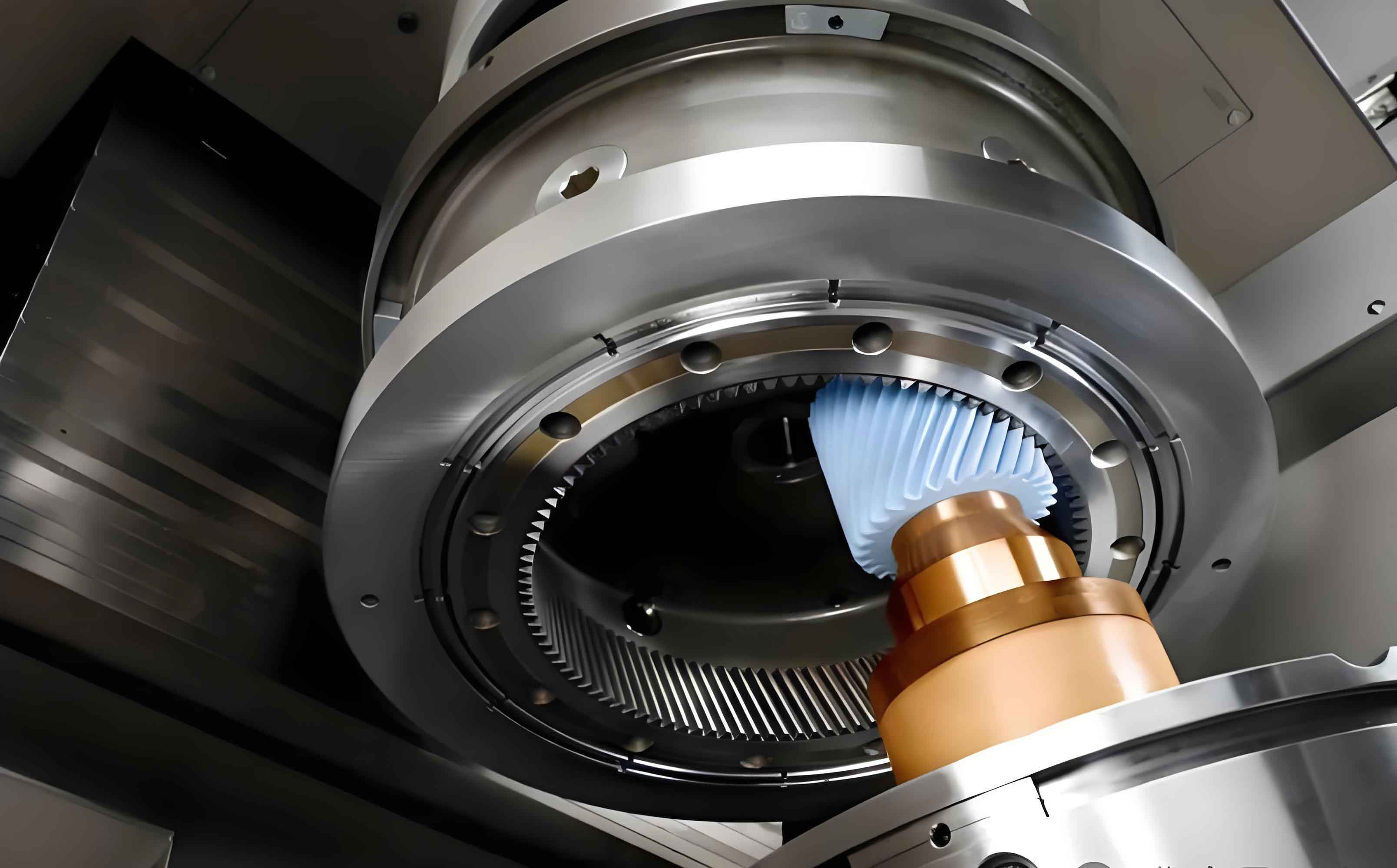
Internal gear honing is a precision finishing process that employs an internal-toothed honing wheel to finish the teeth of an external gear. The process is characterized by crossed-axis engagement between the honing wheel and the workpiece gear.
Basic Configuration and Engagement
The core setup involves an internal honing wheel (the tool) and an external workpiece gear. The honing wheel is typically manufactured from a high-strength alloy steel core, onto which an abrasive layer is bonded. This layer can be a vitrified or resin-bonded matrix impregnated with conventional abrasives like aluminum oxide (Al₂O₃) or silicon carbide (SiC), or more advanced superabrasives like CBN or diamond. The workpiece is a hardened external gear that requires final finishing. The two components are mounted on non-parallel, non-intersecting shafts with a specific axis crossing angle, denoted as $\Sigma$. This crossed-axis arrangement is fundamental to the cutting action in gear honing.
The theoretical engagement between a standard internal gear and an external gear with crossed axes is non-conjugate. If both tooth surfaces were perfect involute helicoids, they would theoretically interfere with each other during meshing. The extent of this theoretical interference increases with a larger axis crossing angle, $\Sigma$, and a smaller difference in the number of teeth between the honing wheel ($z_h$) and the workpiece ($z_w$).
Mathematical Model of the Honing Process
The kinematic relationship is governed by the principle of crossed helical gear engagement. The relative motion between the honing wheel and the workpiece consists of their respective rotations and the defined axis crossing. The surface speed vector at the point of contact generates the cutting action. A key parameter is the theoretical helix angle relationship. If $\beta_h$ is the helix angle of the honing wheel and $\beta_w$ is the helix angle of the workpiece, the axis crossing angle $\Sigma$ is ideally set as the absolute difference between them, considering hand:
$$ \Sigma = |\beta_h \pm \beta_w| $$
where the plus sign is used for gears with opposite hand, and the minus sign for gears with the same hand. The theoretical sliding velocity $v_s$ along the tooth flank, which is responsible for the abrasive cutting action, can be expressed as:
$$ v_s = \sqrt{v_{t,h}^2 + v_{t,w}^2 – 2 \cdot v_{t,h} \cdot v_{t,w} \cdot \cos(\Sigma)} $$
where $v_{t,h}$ and $v_{t,w}$ are the tangential velocities of the honing wheel and workpiece at the pitch point, respectively.
The Role of the Dressing Process and Double Enveloping
To achieve a precise and controlled finishing action, the honing wheel is not used in its “as-manufactured” state. It must be precisely dressed or profiled to create the correct generating surface. This is accomplished using a high-precision, gear-shaped diamond or CBN dressing roll. During dressing, the dressing roll and the honing wheel engage in a synchronized crossed-axis motion similar to the honing process itself. The superabrasive particles on the dressing roll precisely shape the bond material of the honing wheel, generating its working profile.
This leads to the concept of double enveloping, which is central to the accuracy of internal gear honing:
- First Enveloping (Dressing): The dressing roll (with a perfect involute profile) generates its envelope surface onto the honing wheel. The honing wheel tooth surface becomes the conjugate envelope to the dressing roll’s profile.
- Second Enveloping (Honing): During honing, this newly generated honing wheel surface then acts as the tool to generate its envelope onto the workpiece gear tooth surface.
If the kinematic conditions (axis angle, speed ratio) during dressing and honing are identical, the workpiece tooth surface produced by this double enveloping process will be a precise replica of the original dressing roll profile. This means the final accuracy of the honed gear is primarily a function of the accuracy and profile of the diamond dressing roll. The honing wheel essentially becomes a transferring medium. This relationship is summarized in the following table:
| Process Stage | Master/Tool | Target | Surface Generation | Key to Final Accuracy |
|---|---|---|---|---|
| Dressing | Diamond Dressing Roll (Involute) | Honing Wheel | First Enveloping | Defines the honing wheel’s cutting profile |
| Honing | Dressed Honing Wheel | Workpiece Gear | Second Enveloping | Transfers dressing roll profile to workpiece |
Contact Conditions and Stock Removal
In contrast to the theoretical point contact of crossed helical gears, the dressed honing wheel and the workpiece establish an instantaneous line contact. This contact line sweeps across the entire tooth flank due to the relative rolling and sliding motion. The nature of this contact is crucial for efficient stock removal and error correction. For a right-handed workpiece gear honed by a right-handed internal wheel, the contact pattern typically evolves as follows:
- On the Drive Side: The contact line often initiates near the tip at one end of the tooth face width and progresses diagonally across the flank, exiting near the root at the opposite end.
- On the Coast Side: The contact line follows a complementary path, starting near the root and exiting near the tip.
This full-face-width contact eliminates the need for a traditional axial traverse feed to cover the tooth width, simplifying machine kinematics. However, a slow axial oscillation is frequently applied. This serves two main purposes: to average out any localized form errors across the gear’s face width and to distribute wear more evenly across the honing wheel’s active profile, thereby extending its life between dressing cycles.
The Evolution and Impact of Superabrasives in Gear Honing
The true potential of internal gear honing was unlocked with the industrial maturation of superabrasive materials. While the concept and early machines date back decades, the introduction of reliable, cost-effective diamond and CBN abrasives transformed the process in the 1980s.
Superabrasive Tools: Dressing Rolls and Honing Wheels
The heart of the modern process lies in two superabrasive components:
1. The Dressing Roll: This is a precision gear, usually made of steel, whose teeth are plated with a single layer of diamond or CBN grit. Its geometric accuracy directly dictates the achievable accuracy of the honed gears. It is the “master” in the process. The dressing process regenerates the honing wheel’s profile, correcting wear and maintaining process stability.
2. The Honing Wheel: Two primary types exist:
- Conventional Bonded Wheels: Made with resin or vitrified bonds impregnated with Al₂O₃ or SiC. They are economical but wear faster and have limited cutting efficiency on very hard materials.
- Superabrasive Honing Wheels: These use a metal, resin, or hybrid bond impregnated with CBN or diamond grit. CBN is particularly suitable for finishing hardened ferrous alloys (typical gear steels), while diamond is used for non-ferrous materials or carbides. Their extreme hardness and wear resistance provide dramatically longer tool life, consistent cutting performance, and the ability to achieve finer finishes and tighter tolerances.
| Abrasive Type | Knoop Hardness (kg/mm²) | Primary Application in Gear Honing | Key Advantage | Limitation |
|---|---|---|---|---|
| Aluminum Oxide (Al₂O₃) | ~2000 | Soft finishing, preliminary honing | Low cost | High wear, limited on hard steels |
| Silicon Carbide (SiC) | ~2500 | Cast iron, non-ferrous metals | Sharp, brittle grains | Not suitable for hard steels |
| Cubic Boron Nitride (CBN) | ~4500 | Hardened alloy steels (HRC > 45) | Exceptional hardness & thermal stability in steel | Higher cost, reactive with ferrous at high T |
| Diamond | ~7000 | Carbides, ceramics, non-ferrous metals | Extreme hardness and wear resistance | Reacts with ferrous metals, highest cost |
Process Advantages Enabled by Superabrasives
The synergy of internal meshing kinematics and superabrasive technology yields a unique set of benefits for gear honing:
- Superior Error Correction: The line contact and continuous rolling/sliding action effectively average and correct profile ($f_f$), lead ($f_\beta$), and pitch errors. It is exceptionally effective at reducing tooth-to-tooth composite error and total cumulative pitch error.
- Excellent Surface Finish: The process generates a characteristic cross-hatch surface pattern, ideal for oil retention and wear-in. Surface roughness values in the range of Ra 0.4 μm to Ra 0.1 μm (and even lower) are routinely achievable.
- No “Honing Tooth Form” Distortion: A critical issue with some gear shaving and external gear honing processes is mid-point tooth form distortion caused by a low contact ratio and reversing cutting forces. The internal honing process, with its higher and more stable contact conditions, virtually eliminates this problem, producing a true involute profile.
- High Process Efficiency: Cycle times are short, typically ranging from 1 to 4 minutes per gear for automotive-sized components, making it ideal for high-volume production.
- Improved Dimensional Stability: The process induces minimal residual stresses and generates minimal heat compared to grinding, preserving the metallurgical integrity of the case-hardened layer.
The improvement in gear quality can be quantified. A gear entering the gear honing cell at ISO grade 8 or 9 can consistently be finished to grade 6 or 7, with critical parameters like profile and lead often showing the most dramatic improvement. The relationship between stock removal and error correction is not purely linear but follows a trend of diminishing returns, which can be modeled for process optimization:
$$ \Delta E \approx k \cdot \sqrt{S_r} $$
where $\Delta E$ is the reduction in a specific error (e.g., profile deviation), $S_r$ is the stock removed from the tooth flank, and $k$ is a process-dependent constant related to wheel sharpness, pressure, and kinematic accuracy.
Process Parameters and Honing Wheel Design Considerations
Successful implementation of internal gear honing requires careful selection and control of numerous interrelated parameters.
Critical Process Parameters
| Parameter | Symbol | Typical Range / Consideration | Influence on Process |
|---|---|---|---|
| Axis Crossing Angle | $\Sigma$ | 10° – 30° | Controls sliding speed, cutting action aggressiveness, and contact pattern. |
| Honing Wheel Speed | $n_h$ | 500 – 2000 rpm | Higher speeds increase productivity but require dynamic balance and coolant efficiency. |
| Workpiece Speed | $n_w$ | Derived from speed ratio $i = z_h / z_w$ | Determines the rolling motion and meshing frequency. |
| Radial Infeed | $F_r$ | Controlled, often in multiple stages (rough/finish) | Directly controls cutting pressure and stock removal rate. |
| Axial Oscillation Stroke/Frequency | $L_a$, $f_a$ | Stroke = Face width; Freq = 20-100 strokes/min | Averages wear, improves finish uniformity, prevents groove formation. |
| Honing Time | $t_h$ | 30 – 240 seconds | Determines total stock removal. Must be optimized for correction vs. cycle time. |
| Coolant Type & Flow | – | High-pressure, filtered oil-based coolant | Critical for heat dissipation, chip evacuation, and wheel cleanliness. |
Honing Wheel Specification
Designing the honing wheel involves several key choices:
- Number of Teeth ($z_h$): Should be significantly greater than the workpiece teeth ($z_w$) to ensure a high contact ratio and smooth operation. A large difference also minimizes the theoretical interference mentioned earlier. Common differences range from 20 to over 100 teeth.
- Profile Modification: The honing wheel is often dressed with intentional profile modifications (tip and root relief, crowning) so that it imparts the desired modifications onto the workpiece gear. This is a powerful feature for optimizing gear contact patterns under load.
- Abrasive Grit Size and Concentration: Finer grits (e.g., CBN #400-#800) produce better surface finish but lower cutting rates. Coarser grits (#180-#320) remove stock faster. Concentration (the amount of abrasive in the bond) affects wheel aggressiveness and life.
The theoretical center distance $a$ during honing, considering the crossed axes, is a critical setting derived from the basic gear geometry and the axis angle:
$$ a = \frac{m_n (z_w – z_h)}{2 \cos \beta} $$
where $m_n$ is the normal module and $\beta$ is the reference helix angle (assuming both gears have the same $\beta$ but opposite hand for $\Sigma = 2\beta$). In practice, the machine is set to a “working center distance” that includes a calculated offset to apply the correct honing pressure.
Comparison with Other Gear Finishing Processes
To appreciate the niche of internal gear honing, it is instructive to compare it with other common finishing methods for hardened gears.
| Process | Tool | Material Removal Mechanism | Typical Accuracy Improvement | Best For | Limitations |
|---|---|---|---|---|---|
| Internal Gear Honing | Internal superabrasive wheel | Continuous line contact, sliding/rolling, abrasive cutting | Can improve 1-3 grades (e.g., 8→6) | High-volume batch production of medium-module gears (auto, truck) | Limited to external gears, requires dedicated dressing system. |
| Gear Grinding (Form/Generating) | Dressed grinding wheel | Discrete point contact, high-speed abrasive machining | High precision, can achieve grade 3-5 | High-precision, low-volume gears (aerospace, wind power), large gears | Higher cost, thermal damage risk, lower production rate. |
| External Gear Honing | External helical honing gear | Point contact, crossed-axis sliding | Improves surface finish, limited error correction (e.g., 8→7) | Improving surface finish of hardened gears, simple setup. | Prone to mid-point form distortion, less effective for lead correction. |
| Hard Gear Shaving (Skiving) | Hardened skiving cutter | Interlocking teeth, generating cut with negative rake | Good for lead/profile, high productivity | High-volume finishing of case-hardened gears prior to final honing/grinding. | Requires very rigid machine, cutter is complex and expensive. |
Industrial Applications and Future Perspectives
The primary domain of internal gear honing is the mass production of transmission gears for the automotive industry. This includes gears for passenger car manual and automatic transmissions, heavy-duty truck transmissions, and drivetrain components. The process is particularly advantageous for finishing helical gears and gears with integral shoulders or clusters, where other processes like grinding face accessibility challenges.
A typical application flow is:
Pre-hone Processing: Gear Hobbing/Shapering -> Carburizing and Hardening -> (Optional: Hard Skiving) -> Internal Gear Honing -> Washing & Inspection.
The future development of gear honing is focused on several key areas:
- Intelligent Process Control: Integration of in-process measurement sensors (acoustic emission, force/torque monitoring) to enable adaptive control of infeed and dressing cycles, optimizing wheel life and part quality in real-time.
- Advanced Machine Platforms: Development of more flexible, multi-axis CNC gear honing machines that can handle a wider range of gear types and incorporate integrated measurement and correction loops.
- Next-Generation Abrasives and Bonds: Research into engineered abrasive grain shapes, nano-crystalline superabrasives, and advanced bond systems (hybrid metal-resin, vitrified bonds for CBN) to further push the limits of tool life, cutting speed, and surface integrity.
- Dry or Minimal Quantity Lubrication (MQL) Honing: Environmental and cost pressures are driving research into near-dry gear honing processes, requiring significant advancements in wheel technology and thermal management.
- Simulation and Digital Twins: Advanced software for simulating the honing process—predicting contact patterns, stock removal, form generation, and thermal effects—is becoming crucial for first-time-right process design and virtual optimization.
The mathematical modeling of the process is also becoming more sophisticated, moving beyond kinematic models to include cutting mechanics. A simplified force model can consider the normal honing force $F_n$ as a function of process parameters:
$$ F_n = K \cdot A_c \cdot v_s^{p} $$
where $K$ is a specific cutting pressure constant (dependent on workpiece material, abrasive, and bond), $A_c$ is the instantaneous contact area, $v_s$ is the sliding velocity, and $p$ is an exponent typically less than 1. Such models help in predicting power consumption and optimizing parameters for efficient stock removal without excessive wheel wear.
In conclusion, internal gear honing has matured from an experimental technique into a cornerstone process for high-quality, high-volume gear production. The combination of its unique crossed-axis internal meshing kinematics with the relentless performance of superabrasive tools creates a finishing method that is both highly productive and capable of delivering significant geometric improvements. As the demands for quieter, more efficient, and more durable gears continue to rise across all sectors of industry, the role of advanced gear honing technology is set to become even more prominent, driven by continuous innovation in machine tools, abrasive science, and digital process integration.