
In modern industrial applications, internal involute gears are extensively utilized across sectors such as mining, automotive, and heavy machinery. The quality and precision of these gears directly impact the overall performance and reliability of mechanical assemblies. As a researcher deeply involved in gear manufacturing technology, I have focused on advancing the theoretical foundations of gear cutting processes, particularly for internal gears. This article presents a comprehensive analysis of the cutting theory for internal involute gears, employing modern meshing theory and geometric principles to develop a robust mathematical model for gear cutting. The goal is to enhance the accuracy and efficiency of gear production through numerical control (NC) systems, thereby meeting the stringent demands of industrial applications.
The formation of an involute tooth profile is fundamental to understanding gear cutting. An involute curve can be visualized as the trajectory traced by a point on a taut string as it unwinds from a base circle. This geometric principle underpins the design and manufacturing of involute gears. Let the base circle have a radius $r_b$. As the string unwinds through an angle $\theta$, the length of the tangent from the point on the involute to the base circle equals the arc length on the base circle, given by $L = r_b \theta$. This relationship indicates that the tangent length changes uniformly with the rotation angle, and the shape of the involute is solely determined by the base circle radius. By correlating each rotation angle of the base circle with a corresponding point on the involute, we can mathematically describe the tooth profile.
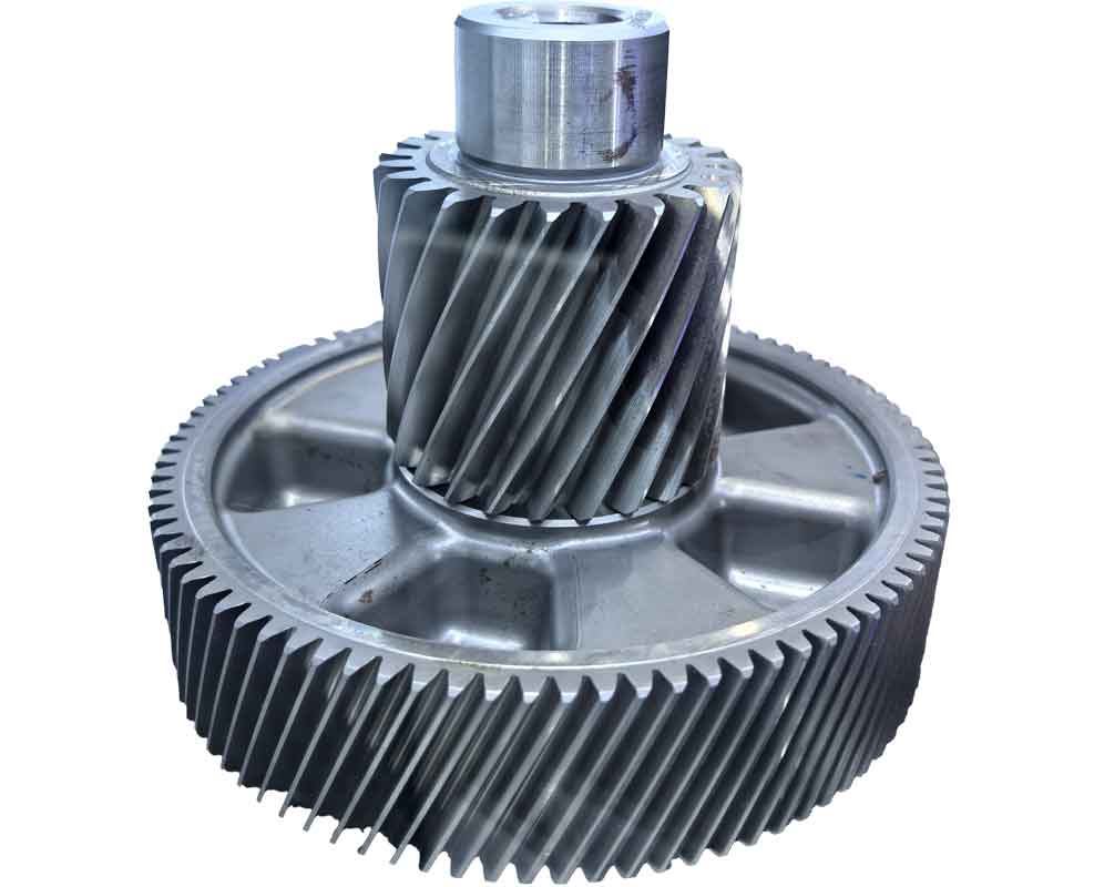
In gear cutting, two primary methods are considered for generating involute profiles. The first mimics the generating principle of gear hobbing, where one cutter simulates the workpiece rotating with the base circle, and another cutter moves linearly along the tangent. However, this approach often involves heavy inertial forces and high demands on servo systems, making implementation challenging. The second method, which I propose and analyze here, uses a NC rotary table to emulate the uniform rotation of the base circle, while a cutter mounted on a power head moves linearly to simulate the changing tangent length. The linear velocity $V$ of the cutter relates to the angular velocity $\omega$ of the rotary table by $V = r_b \omega$. By synchronizing these motions through NC programming, continuous involute profiles can be milled accurately. This method reduces requirements on cutter precision, minimizes cutting forces, and ensures stability, making it advantageous for batch production in gear cutting.
To establish a mathematical model for gear cutting, I define a planar coordinate system with its origin at the center of the base circle and the Y-axis aligned from the center to the starting point of the involute. Let $\theta$ be the unfolding angle, which serves as the variable parameter. The coordinates of any point $A$ on the involute are derived as follows:
$$X_A = r_b \sin \theta – r_b \theta \cos \theta,$$
$$Y_A = r_b \cos \theta + r_b \theta \sin \theta.$$
Here, $r_b$ is the base circle radius, calculated as $r_b = \frac{m z \cos \alpha}{2}$, where $m$ is the module, $z$ is the number of teeth, and $\alpha$ is the pressure angle at the reference circle. The polar radius at point $A$ is $r_A = \frac{r_b}{\cos \alpha_A}$, and the unfolding angle relates to the pressure angle $\alpha_A$ by $\theta = \tan \alpha_A$. These equations form the basis for generating involute tooth profiles during gear cutting.
In NC-based gear cutting, curves are approximated by series of linear segments. To analyze the resulting error, consider a segment of the involute between points $A$ and $B$. The line segment $AB$ approximates the true involute arc, with the maximum deviation $\delta$ occurring at the midpoint $N$. Let the coordinates of $A$ and $B$ be $(x_A, y_A)$ and $(x_B, y_B)$, respectively. The coordinates of $N$ are:
$$x_N = \frac{x_A + x_B}{2}, \quad y_N = \frac{y_A + y_B}{2}.$$
The distance from the origin $O$ to $N$ is:
$$ON = \sqrt{x_N^2 + y_N^2}.$$
The unfolding angle $\theta_M$ at point $M$ on the involute corresponding to $N$ is:
$$\theta_M = \arctan\left(\frac{x_N}{y_N}\right) + \arccos\left(\frac{r_b}{ON}\right).$$
The length of the tangent from $M$ to the base circle is $M’M = r_b \theta_M$, where $M’$ is the point of tangency. The length $M’N$ is:
$$M’N = \sqrt{ON^2 – r_b^2}.$$
Thus, the maximum normal error due to linear approximation is:
$$\delta = MN = M’M – M’N = r_b \theta_M – \sqrt{ON^2 – r_b^2}.$$
This error must be evaluated against the required machining tolerance. If $\delta$ exceeds the precision limit, the angular increment $\Delta\theta$ for NC interpolation must be reduced iteratively until the error meets specifications. This process ensures high accuracy in gear cutting operations.
To model the gear cutting process dynamically, I establish two coordinate systems. The cutter coordinate system $\sigma_1 = \{O_1(t); \mathbf{i}_1, \mathbf{j}_1, \mathbf{k}_1\}$ is fixed relative to the cutter, with unit vectors independent of time and cutter rotation. The workpiece coordinate system $\sigma_2 = \{O_2; \mathbf{i}_2(t), \mathbf{j}_2(t), \mathbf{k}_2(t)\}$ is attached to the gear blank, rotating about its axis. At time $t=0$, the systems align: $\mathbf{i}_2(0) = \mathbf{i}_1$, $\mathbf{j}_2(0) = \mathbf{j}_1$, $\mathbf{k}_2(0) = \mathbf{k}_1$. As the workpiece rotates clockwise by an angle $\theta(t)$, the transformation equations are:
$$\mathbf{i}_2(t) = \cos \theta(t) \mathbf{i}_1 – \sin \theta(t) \mathbf{j}_1,$$
$$\mathbf{j}_2(t) = \sin \theta(t) \mathbf{i}_1 + \cos \theta(t) \mathbf{j}_1,$$
$$\mathbf{k}_2(t) = \mathbf{k}_1.$$
Let the pitch circle radius of the workpiece be $r$, and the angular velocity be $\frac{d\theta}{dt} = \omega$ (normalized to 1 for simplicity). To maintain proper meshing in gear cutting, the cutter must translate laterally by a distance $r \theta$ in the direction of rotation. Thus, the displacement vector $\mathbf{m}$ for the cutter is:
$$\mathbf{m} = r \theta \mathbf{i}_1 + r \mathbf{j}_1.$$
This model synchronizes rotary and linear motions, enabling precise generation of involute teeth across various gear parameters. The equations highlight the interplay between kinematics and geometry in gear cutting.
The theoretical basis for the milling process also involves force analysis to ensure stability. In gear cutting, balanced cutting forces are crucial to prevent chatter and vibration. I consider the dynamics of the power head, which is designed with sufficient mass and rigidity to absorb fluctuations. The cutting force $\mathbf{F}_c$ acting on the cutter can be resolved into tangential, radial, and axial components. For a balanced design, the net force should minimize torsional moments. Assuming symmetric cutter engagement, the force components are:
$$F_t = K_t a_p f, \quad F_r = K_r F_t, \quad F_a = K_a F_t,$$
where $K_t$, $K_r$, and $K_a$ are specific cutting coefficients, $a_p$ is the depth of cut, and $f$ is the feed rate. To maintain equilibrium, the power head’s center of mass should align with the line of action of the resultant force. This reduces vibrations and enhances surface finish in gear cutting. Table 1 summarizes key parameters and their typical ranges for internal gear milling.
| Parameter | Symbol | Typical Range | Description |
|---|---|---|---|
| Module | $m$ | 1–10 mm | Size parameter of the gear tooth |
| Number of Teeth | $z$ | 20–200 | Total teeth on the internal gear |
| Pressure Angle | $\alpha$ | 20°–25° | Angle at reference circle |
| Base Circle Radius | $r_b$ | Derived from $m$, $z$, $\alpha$ | Fundamental for involute generation |
| Cutting Depth | $a_p$ | 0.1–2 mm | Depth of material removed per pass |
| Feed Rate | $f$ | 0.05–0.3 mm/rev | Linear advance per revolution |
| Angular Velocity | $\omega$ | 0.1–5 rad/s | Rotational speed of workpiece |
Error control is integral to precision gear cutting. Beyond linear approximation errors, systemic errors from machine tool inaccuracies must be addressed. I evaluate total error $\Delta$ as a combination of geometric, kinematic, and dynamic errors:
$$\Delta = \sqrt{\delta_g^2 + \delta_k^2 + \delta_d^2},$$
where $\delta_g$ is geometric error from tooth profile deviation, $\delta_k$ is kinematic error from motion synchronization, and $\delta_d$ is dynamic error from vibrations. For high-quality gear cutting, $\Delta$ should not exceed 0.01 mm for standard industrial gears. To achieve this, iterative compensation algorithms are implemented in NC systems, adjusting tool paths based on real-time feedback. Table 2 outlines a step-by-step error minimization procedure.
| Step | Action | Objective | Tools/Methods |
|---|---|---|---|
| 1 | Calculate theoretical involute points | Define ideal tooth profile | Equations $X_A$, $Y_A$ |
| 2 | Perform linear interpolation | Approximate curve with segments | NC interpolation algorithms |
| 3 | Compute maximum error $\delta$ | Assess approximation accuracy | Error formula $\delta = r_b \theta_M – \sqrt{ON^2 – r_b^2}$ |
| 4 | Compare $\delta$ with tolerance $\tau$ | Determine if precision is met | Threshold check: $\delta \leq \tau$ |
| 5 | If $\delta > \tau$, reduce $\Delta\theta$ | Refine interpolation increment | Bisection or adaptive methods |
| 6 | Update NC code and re-simulate | Verify improved accuracy | CAD/CAM software |
| 7 | Implement on machine tool | Execute actual gear cutting | CNC milling machine |
| 8 | Measure produced gear | Validate against standards | Coordinate measuring machine (CMM) |
The gear cutting model is further generalized by incorporating time-dependent variables. Let $t$ denote time, with the workpiece rotation given by $\theta(t) = \omega t$. The cutter translation along the X-axis is $x_c(t) = r \omega t$, and along the Y-axis is $y_c(t) = r$. This yields parametric equations for the cutter path relative to the workpiece:
$$x(t) = r \omega t \cos(\omega t) – r \sin(\omega t),$$
$$y(t) = r \omega t \sin(\omega t) + r \cos(\omega t).$$
These equations describe a trochoidal motion essential for generating the involute via gear cutting. The instantaneous cutting point corresponds to the intersection of the cutter envelope and the workpiece surface, derived using differential geometry. The condition for proper meshing is expressed as the equality of normal vectors:
$$\mathbf{n}_c \cdot \mathbf{v}_r = 0,$$
where $\mathbf{n}_c$ is the normal to the cutter surface and $\mathbf{v}_r$ is the relative velocity between cutter and workpiece. This ensures continuous contact and smooth tooth formation during gear cutting.
Material removal rates (MRR) are critical for efficiency in gear cutting. For a cylindrical end-mill cutter of diameter $d_c$, the MRR is approximated by:
$$\text{MRR} = a_p f v_c,$$
where $v_c$ is the cutting speed. Optimizing these parameters reduces cycle times while maintaining tool life. I also consider thermal effects, as heat generation during gear cutting can affect dimensional accuracy. The temperature rise $\Delta T$ is estimated using:
$$\Delta T = \frac{P_c}{\rho C_p V_w},$$
where $P_c$ is the cutting power, $\rho$ is material density, $C_p$ is specific heat, and $V_w$ is the workpiece volume engaged. Cooling strategies, such as flood coolant or mist, are employed to mitigate thermal distortion.
The application of this gear cutting theory to NC machine design has yielded promising results. A prototype milling machine was developed based on the mathematical models, incorporating synchronized rotary and linear axes. Testing involved cutting internal gears with modules ranging from 2 to 5 mm and tooth counts from 30 to 100. The gears were evaluated for profile error, pitch accuracy, and surface roughness. Measurements showed that profile deviations were within ISO 1328 Class 7 tolerances, confirming the model’s validity. The stability of the gear cutting process was evidenced by minimal chatter marks and consistent tooth geometry across batches.
Moreover, the flexibility of the NC approach allows for adaptive gear cutting. By modifying the base circle radius $r_b$ in the control program, different gear designs can be produced on the same machine without hardware changes. This is particularly advantageous for custom or low-volume production. The integration of real-time monitoring systems further enhances precision, adjusting feed rates dynamically based on sensor feedback to compensate for tool wear or material variations.
In conclusion, the theoretical analysis of gear cutting for internal involute gears provides a comprehensive framework for high-precision manufacturing. The mathematical models derived from involute geometry and kinematics enable accurate simulation and control of the cutting process. Error analysis ensures that tolerances are met through iterative refinement, while force and thermal considerations promote stable and efficient operations. The successful implementation in prototype machinery demonstrates the practicality of this approach, offering a reliable solution for industrial gear production. Future work may explore advanced materials, multi-axis gear cutting, and AI-driven optimization to further push the boundaries of gear manufacturing technology.