
The pursuit of higher power density and transmission efficiency remains a primary goal in the field of mechanical drives. Among various solutions, gear drives with a low pinion tooth count are a key enabler for achieving this objective. Hyperboloidal gears, particularly those configured for high reduction ratios (HRH gears), offer significant advantages including high contact ratio, minimal number of teeth, lightweight design, and superior efficiency. These characteristics make them exceptionally promising for applications in highly integrated electromechanical power transmission systems. However, the complex spatial geometry of HRH gear tooth surfaces presents a formidable challenge. Conventional design and machining calculation methods often fall short in effectively controlling the meshing quality and contact characteristics of these highly skewed surfaces. The intense local curvature and substantial twist inherent to HRH gear flanks make traditional correction techniques, such as the Hypoid Format Tilt (HFT) or Hypoid Generating Modified (HGM) methods, inadequate or inapplicable, especially for gears with very small modules. This necessitates the development of a more comprehensive and robust methodology for the precise calculation of machining parameters and the control of the tooth surface’s differential geometry to ensure optimal meshing performance.
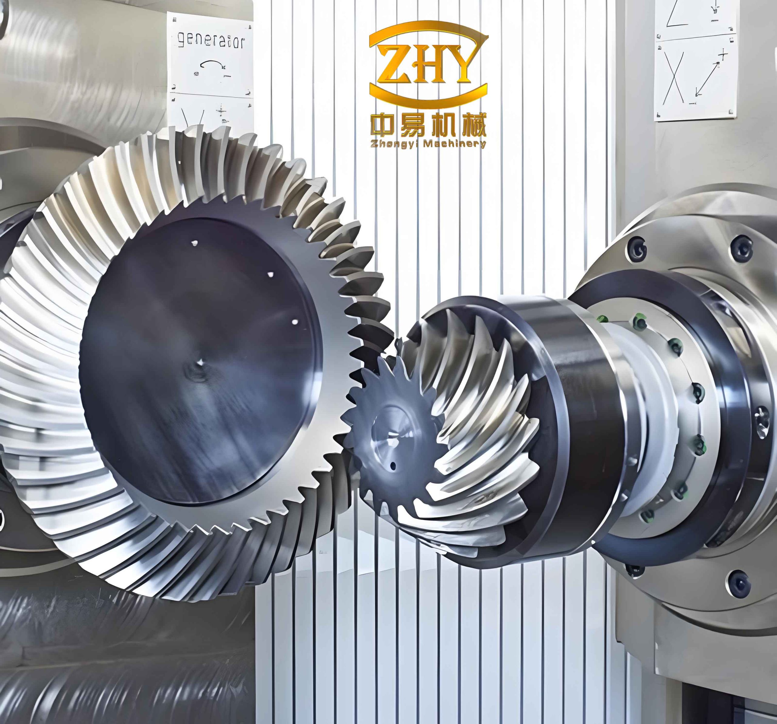
This article presents a novel, integrated approach based on the principle of surface synthesis to address these challenges. The method begins with establishing a generalized mathematical model for spatial gearing, followed by the introduction of a tailored cutter profiling strategy for the gear member. The core of the methodology involves synthesizing multiple key surfaces—the theoretical generating surface, the desired pinion flank, and a controlled ease-off topography—to derive accurate machine-tool settings. This process enables precise control over the local and global topology of the hyperboloidal gear flanks, ensuring high-quality meshing. The validity of the proposed method is subsequently confirmed through both computer-aided contact simulation and physical prototype testing, including vibration analysis.
Generalized Mathematical Model for Spatial Gearing
The foundation for analyzing and generating hyperboloidal gears lies in a precise mathematical description of spatial gear meshing. Consider a pair of gears in crossed-axis arrangement, denoted as surfaces $\Sigma^{(1)}$ and $\Sigma^{(2)}$. A set of coordinate systems is established to describe their relative motion and geometry, as shown in Figure 1. Coordinate systems $S_1 (O_1-x_1, y_1, z_1)$ and $S_2 (O_2-x_2, y_2, z_2)$ are rigidly attached to pinion and gear, respectively. Fixed coordinate systems include $S_0$, $S_d$, and $S_D$. The $z_0$-axis coincides with the gear rotation axis $z_2$. The relationship between $S_d$ and $S_0$ involves a translation $O_0O_d = [0, 0, -E]^T$. The system $S_D$ is obtained from $S_d$ by a translation $O_dO_D = [0, 0, P]^T$ and a rotation of $(90^\circ – \gamma)$ around the $x_d$-axis. The instantaneous rotation angles are $\phi_1$ and $\phi_2$, with angular velocities $\omega_1$ and $\omega_2$.
For this spatial meshing scenario, six parameters $(E, P, G, \gamma, \phi_1, \phi_2)$ describe the relative position and orientation. However, for a defined gear pair with fixed axis configuration, a single degree-of-freedom exists, linking $\phi_1$ and $\phi_2$ through the gear ratio. Based on coordinate transformations and the condition for continuous contact, the general meshing equation can be derived as:
$$ \mathbf{n} \cdot \mathbf{v}^{(12)} = f(u, v, \phi) = 0 $$
where $\mathbf{n}$ is the unit normal vector to the tooth surface, $\mathbf{v}^{(12)}$ is the relative velocity vector at the contact point, and $u, v$ are surface parameters. For the specific case of constant relative position and crossed axes (with $\gamma = 90^\circ$, $G=0$), the meshing equation can be simplified to an explicit form:
$$ U \cos\phi + V \sin\phi = W, \quad \text{where} \quad \tan \epsilon = \frac{V}{U} $$
The terms $U, V, W$ are functions of the surface coordinates and normal vector components $(n_x, n_y, n_z)$ and the machine setup parameters $E$ and $m_{12} = \omega_2 / \omega_1$:
$$
\begin{aligned}
U &= n_y E – n_z y + n_x z \\
V &= -n_x E – n_z x – n_y z \\
W &= n_x y – n_y x + m_{12} n_z E
\end{aligned}
$$
This generalized form is crucial for subsequent derivations of both gear generation and meshing simulation for hyperboloidal gears.
Gear Member Manufacturing with Cutter Profiling
Formate Cutting of the Gear
For the gear member in a hyperboloidal gear set, formate cutting (non-generating) is typically employed for higher efficiency. The coordinate systems for gear machining are illustrated in Figure 2. The gear tooth surface $\Sigma_2$ is produced by the envelope of the cutter head surface. The surface equation and its unit normal in the gear coordinate system $S_2$ are obtained via coordinate transformation from the machine coordinate system $S_{m2}$:
$$ \mathbf{r}_2 = \mathbf{T}_{2m2} \cdot \mathbf{r}_{m2} + \mathbf{R}_{2}, \quad \mathbf{n}_2 = \mathbf{T}_{2m2} \cdot \mathbf{n}_{m2} $$
where $\mathbf{T}_{2m2}$ is the rotation matrix involving the machine root angle $\delta_{m2}$, and $\mathbf{R}_{2}$ is the translation vector. In the machine system, the cutter surface (assumed as a conical surface) and its normal are given by:
$$ \mathbf{r}_{m2} = \begin{bmatrix} (r_0 + u \sin\alpha) \cos\theta + H \cos\alpha \\ -(r_0 + u \sin\alpha) \sin\theta \\ V – (r_0 + u \sin\alpha) \cos\theta \tan\alpha + u \cos\alpha \end{bmatrix}, \quad \mathbf{n}_{m2} = \begin{bmatrix} \cos\alpha \cos\theta \\ -\cos\alpha \sin\theta \\ -\sin\alpha \end{bmatrix} $$
Here, $r_0$ is the cutter point radius, $\alpha$ is the cutter pressure angle, and $H, V$ are machine settings. Parameters $u$ and $\theta$ define the cutter surface.
Cutter Profiling for Curvature Correction
Formate cutting with a straight-sided cutter inherently produces insufficient longitudinal curvature on the gear tooth flank. To achieve the desired point contact and correct meshing with the pinion, the pinion flank normally requires complex curvature modifications via HFT or HGM methods. For small-module hyperboloidal gears, these methods are often impractical. Therefore, an alternative strategy is proposed: modifying the cutter profile for the gear, thereby imprinting the necessary corrective curvature directly onto the gear tooth surface. This modified cutter surface acts as an “osculating surface” $\Sigma_g$ that matches the desired gear flank curvature at a reference point.
The modification is applied in two directions (see Figure 3):
1. Profile Direction (y_H) Modification: A parabolic modification is applied to the cutter pressure angle. At the reference point $M_0(u_0, \theta_0)$ with nominal pressure angle $\alpha_0$, the modification function $w(u)$ and its derivative are:
$$ w = 0.5 a_1 (u – u_0)^2, \quad w’ = a_1 (u – u_0) $$
The modified pressure angle becomes:
$$ \alpha_2(u) = \alpha_0 + \arctan(w’) $$
2. Lengthwise Direction (x_L) Modification: Similarly, a parabolic modification is applied to the cutter lead angle (or equivalent parameter $\theta$) to control the lengthwise curvature:
$$ L = 0.5 a_2 (\theta – \theta_0)^2, \quad L’ = a_2 (\theta – \theta_0) $$
The modified parameter becomes:
$$ \theta_2(\theta) = \theta_0 + \arctan(L’) $$
Substituting $\alpha_2(u)$ and $\theta_2(\theta)$ into the original cutter surface equations yields the modified cutter surface $\Sigma_g$, characterized by controlled curvatures $k_h$ and $k_v$ in the profile and lengthwise directions, respectively. The modification coefficients $a_1$ and $a_2$ are determined based on the required ease-off topography, as explained in the next section.
Surface Synthesis for Topology Modification Control
The core innovation of this methodology is the surface synthesis approach. Instead of local point-based correction, the entire pinion tooth surface is designed by synthesizing three key surfaces: the gear’s modified flank $\Sigma_g$, a virtual conjugate pinion surface $\Sigma_s$ derived from $\Sigma_g$, and the physical generating surface of the pinion machine $\Sigma_1$. The goal is to make $\Sigma_s$ and $\Sigma_1$ coincide by optimally selecting machine settings.
Defining the Ease-off Topology
The desired contact pattern and transmission error behavior are predefined via an “ease-off” surface—a controlled deviation applied to the gear flank. This deviation is often defined by an elliptical gradient field centered at the design contact point $M_0$, as shown in Figure 4. The ellipse equation is:
$$ \frac{x^2}{a^2} + \frac{y^2}{b^2} = \frac{1}{4} $$
where $a$ and $b$ define the semi-axes of the contact ellipse, and $\lambda$ defines its orientation relative to the lengthwise direction. The ease-off value $\delta$ at the ellipse boundary is a small predefined amount (e.g., 0.01 mm). The corresponding principal curvature changes $\Delta k_a$ and $\Delta k_b$ induced by this ease-off are:
$$ \Delta k_a = \frac{8\delta}{a^2}, \quad \Delta k_b = \frac{8\delta}{b^2} $$
Determining the Osculating Surface $\Sigma_g$
The longitudinal and transverse curvatures of the formate-cut gear are $(1/\rho_c, 1/r_2)$. The ease-off topography modifies these. Using Euler’s formula, the principal curvatures $k_a$ and $k_b$ of the target osculating surface $\Sigma_g$ in the ellipse axis directions are:
$$ k_a = \frac{1}{\rho_c} + \Delta k_a \cos^2\lambda + \Delta k_b \sin^2\lambda $$
$$ k_b = \frac{1}{r_2} + \Delta k_a \sin^2\lambda + \Delta k_b \cos^2\lambda $$
Projecting these onto the profile ($h$) and lengthwise ($v$) directions yields the target curvatures $k_h$ and $k_v$ for the modified cutter:
$$ k_h = k_a \cos^2\lambda + k_b \sin^2\lambda $$
$$ k_v = k_a \sin^2\lambda + k_b \cos^2\lambda $$
Finally, the cutter modification coefficients are calculated from these target curvatures:
$$ a_1 = \frac{k_h – (1/r_2)}{\cos \alpha_0}, \quad a_2 = k_v – \frac{1}{\rho_c} $$
These coefficients define the modified cutter surface $\Sigma_g(\mathbf{r}_g, \mathbf{n}_g)$.
Conjugate Pinion Surface $\Sigma_s$
The theoretical pinion tooth surface $\Sigma_s$ that is perfectly conjugate to the modified gear surface $\Sigma_g$ is obtained by solving the meshing equation. For the specific case of a hypoid pair with vertical offset ($\gamma=90^\circ$, $G=0$), the terms $U, V, W$ from the general meshing equation become:
$$
\begin{aligned}
U &= n_{gy}E – n_{gz}y_g + n_{gx}z_g \\
V &= -n_{gx}E – n_{gz}x_g – n_{gy}z_g \\
W &= n_{gx}y_g – n_{gy}x_g + m_{12} n_{gz}E
\end{aligned}
$$
where $(x_g, y_g, z_g)$ and $(n_{gx}, n_{gy}, n_{gz})$ are components of $\mathbf{r}_g$ and $\mathbf{n}_g$. Solving the meshing equation $U \cos\phi_2 + V \sin\phi_2 = W$ yields the meshing phase angle $\phi_2$ for each point on $\Sigma_g$. Applying the coordinate transformation from $S_2$ to $S_1$ then gives the conjugate pinion surface $\Sigma_s(\mathbf{r}_s, \mathbf{n}_s)$.
Pinion Machine Generating Surface $\Sigma_1$
The pinion is generated on a hypoid generator, whose kinematics are described in Figure 5. The generating surface is the cutter head surface, defined in its own coordinate system $S_t$. The machine settings include radial setting $S_r$, angular setting $q$, machine center to back $E_m$, sliding base setting $X_G$, machine root angle $\gamma_m$, and ratio $m_{1p}$ between cradle rotation $\phi_p$ and pinion rotation $\phi_1$. The surface $\Sigma_1$ generated by this machine, along with its normal, can be expressed as functions of these settings and the cutter parameters $(r_t, \alpha_1)$:
$$ \mathbf{r}_1 = \mathbf{r}_1(u_1, \theta_1; S_r, q, E_m, X_G, \gamma_m, m_{1p}), \quad \mathbf{n}_1 = \mathbf{n}_1(u_1, \theta_1; \alpha_1) $$
Solving for Pinion Machine Settings
The key step is to find the set of machine settings that make the physically generated surface $\Sigma_1$ match the theoretically required conjugate surface $\Sigma_s$. This involves solving a system of nonlinear equations. The unknowns include:
- Cutter geometry: Point radius $r_t$ and pressure angle $\alpha_1$.
- Machine settings: $S_r, q, E_m, X_G, m_{1p}$ (note: $X_b$ can be derived from $X_G$ and $\gamma_m$).
- Surface parameter correspondence: For a set of $N$ sample points on $\Sigma_s$, the corresponding cutter parameters $(u_1^{(i)}, \theta_1^{(i)})$ are also unknown.
The total number of variables for $N$ sample points is $7 + 2N$. The matching conditions are:
- Position Coincidence: $\mathbf{r}_s^{(i)} – \mathbf{r}_1^{(i)} = 0$ for $i=1,…,N$. This provides $3N$ scalar equations.
- Normal Vector Coincidence: $\mathbf{n}_s^{(i)} – \mathbf{n}_1^{(i)} = 0$ for $i=1,…,N$. This provides $2N$ independent scalar equations (since vectors are unit length).
Thus, we have $5N$ equations to solve for $7 + 2N$ variables. Choosing $N=5$ sample points (e.g., the center and four vertices of the ease-off ellipse) yields 25 equations for 17 variables, forming an over-constrained system. The problem is formulated as a constrained optimization, minimizing the sum of squared errors:
$$ \min \sum_{i=1}^{5} \left( \| \mathbf{r}_s^{(i)} – \mathbf{r}_1^{(i)} \|^2 + w_n \| \mathbf{n}_s^{(i)} – \mathbf{n}_1^{(i)} \|^2 \right) $$
where $w_n$ is a weighting factor. The solution process follows the flowchart in Figure 6, iteratively adjusting the variables until convergence. This surface synthesis directly yields the optimal machining parameters for the hyperboloidal pinion.
| Machining Parameter | Pinion (Concave) | Pinion (Convex) | Gear |
|---|---|---|---|
| Workpiece Tilt Angle $\gamma_m$ (°) | 10.9919 | 10.9919 | 74.7639 |
| Sliding Base $X_b$ (mm) | -1.5253 | -1.5400 | 0 |
| Machine Center to Back $E_m$ (mm) | 39.8843 | 40.2278 | 0 |
| Vertical Offset $X_G$ (mm) | -0.3367 | -0.9467 | 5.3428 |
| Cutter Angular Position $q$ (°) | 75.8424 | 81.5262 | 42.2143 |
| Cutter Radial Setting $S_r$ (mm) | 52.0862 | 51.6782 | 53.1513 |
| Ratio $m_{1p}$ | 20.0152 | 19.7476 | — |
| Cutter Point Radius $r_c$ (mm) | 77.725 | 72.644 | 37.3 / 38.9 |
| Cutter Pressure Angle $\alpha$ (°) | 20.0 | 28.0 | 21.0 |
Table 1 presents the calculated machining parameters for an example HRH hyperboloidal gear pair with a 3:60 ratio, 40 mm offset, and a pinion spiral angle of 72°. These parameters are the direct output of the surface synthesis optimization process.
Tooth Contact Analysis (TCA) Simulation
To verify the design before physical manufacturing, Tooth Contact Analysis (TCA) is performed using the derived surfaces and parameters. For the drive side (gear convex flank mating with pinion concave flank), the results are as follows:
The constructed ease-off topography is shown in Figure 7a. The mismatch at the four corners of the evaluated flank area ranges from 31 to 196 μm. The color gradient map in Figure 7b clearly shows an elliptical distribution of the ease-off values centered on the design point, confirming the successful imprint of the intended topology.
Analyzing this ease-off surface yields the contact line pattern and transmission error (TE). Figure 8a shows the path of contact and the gap between mating flanks along adjacent contact lines. The path exhibits a pronounced diagonal orientation across the face width, a characteristic of high-contact-ratio hyperboloidal gear designs. The maximum gaps at the ends of the contact lines are 128 μm and 166 μm, sufficient to prevent edge-loading under typical operating deflections.
Figure 8b displays the calculated static transmission error for multiple consecutive meshing cycles. The overlapping curves indicate a contact ratio exceeding 5 (precisely 5.2 for this design). The transmission error curve is smooth and of low amplitude, suggesting favorable dynamic characteristics.
These simulation results demonstrate that the surface synthesis method successfully controls the meshing characteristics of the hyperboloidal gears, achieving the desired contact ellipse size, orientation, and high contact ratio.
| Parameter | Value / Observation |
|---|---|
| Ease-off Range | 31 μm to 196 μm (across flank) |
| Contact Pattern Shape | Elliptical, diagonally oriented |
| Max Contact Line End Gap | 128 μm (Toe), 166 μm (Heel) |
| Calculated Contact Ratio | 5.2 |
| Transmission Error | Smooth, low-amplitude curve |
Experimental Validation of Meshing Performance
Contact Pattern Test
A physical prototype of the 3:60 hyperboloidal gear pair was manufactured on a CNC hypoid grinding machine using the parameters from Table 1. The running test (rolling under light load with marking compound) was conducted to inspect the contact pattern. The results are shown in Figure 9. Both the convex and concave flanks exhibit well-defined, elliptical contact patches. The location, size, and orientation of these patches correlate well with the ease-off topology and TCA predictions from Figures 7 and 8. This confirms the accuracy of the calculated machining parameters and the effectiveness of the cutter profiling and surface synthesis approach in controlling the real tooth surface geometry of the hyperboloidal gears.
Vibration Performance Test
A dynamic test was conducted to evaluate the operational performance of the hyperboloidal gear set. A dedicated test rig with a rigid gearbox housing was built. Vibration signals were acquired using an m+p data acquisition system with accelerometers mounted on the output shaft housing in three orthogonal directions: axial (X), radial (Y), and vertical (Z). The axial (X) direction is particularly sensitive to the time-varying meshing forces of hyperboloidal gears and is less influenced by shaft alignment errors, making it the primary indicator of meshing quality.
Figure 11 shows the frequency spectrum of the X-direction vibration under different loads and speeds. The dominant components are the gear mesh frequency ($f_m$) and its harmonics, along with shaft rotational frequency ($f_d$) components. Sidebands are minimal, indicating low modulation from speed fluctuations. A key observation is that the vibration levels at higher load (200 N·m) are more stable and often lower in certain harmonics compared to light load (50 N·m). This is attributed to the high contact ratio of the hyperboloidal gears; under higher load, more tooth pairs share the load, reducing the fluctuation in mesh stiffness and thus the dynamic excitation.
A resonance peak is observed near 140 Hz across different speeds, corresponding to the mesh frequency at 2790 rpm pinion speed, the 2nd harmonic at 1410 rpm, and the 4th harmonic at 720 rpm. The time-domain signals for 1410 rpm (Figure 12) and a zoomed-in view of the 3rd harmonic (Figure 13) reveal a periodic pattern synchronized with the shaft rotation and meshing cycles. The modulation relationship $f = n \cdot f_m + k \cdot f_d$ is evident.
Critically, the vibration spectra are clean, lacking significant broadband noise or erratic spikes, which indicates smooth meshing with minimal impact or severe localized contact. The maximum axial vibration acceleration recorded was below 3.11 m/s², indicating remarkably quiet operation (“quietized” effect). This successful dynamic test validates that the designed hyperboloidal gears possess correct geometry, excellent mesh compatibility, and minimal excitation due to their high contact ratio and controlled transmission error.
| Aspect | Observation & Implication |
|---|---|
| Spectrum Content | Dominant mesh frequency ($f_m$) and shaft frequency ($f_d$) harmonics; minimal sidebands. |
| Load Effect | Higher load (200 N·m) results in more stable vibration vs. light load (50 N·m), demonstrating load-sharing benefit of high contact ratio. |
| Resonance | Peak observed near 140 Hz across tests, identifying a system resonance frequency. |
| Signal Quality | Clean spectra without excessive noise, indicating smooth tooth contact. |
| Vibration Level | Max axial acceleration < 3.11 m/s², confirming low dynamic excitation and quiet operation. |
Conclusion
This study has developed and validated a comprehensive methodology for the design, parameter calculation, and quality control of high reduction ratio (HRH) hyperboloidal gears. The principal contributions and conclusions are summarized as follows:
- Generalized Modeling: A unified spatial gearing model was established, providing a general form of the meshing equation that serves as the foundation for both simulation and generation calculations for hyperboloidal gears.
- Cutter Profiling Strategy: A novel method for profiling the formate cutter was introduced. By applying controlled parabolic modifications in both the profile and lengthwise directions, the necessary corrective curvature can be imparted directly to the gear tooth flank. This solves the critical problem of curvature correction for hyperboloidal gears where traditional pinion-based modification methods are not feasible.
- Surface Synthesis Methodology: The core of the approach is the synthesis of multiple surfaces: the modified gear flank (osculating surface), its theoretical conjugate pinion flank, and the physical generating surface of the pinion machine. By enforcing coincidence between these surfaces through an optimization process, the precise machine-tool settings for the hyperboloidal pinion are determined. This method allows for direct control over the global ease-off topography, enabling precise design of contact ellipse size, orientation, and transmission error.
- Validation: The method was successfully applied to a 3:60 hyperboloidal gear pair. TCA simulations confirmed the desired contact pattern and high contact ratio (5.2). Physical prototype testing yielded excellent contact patterns that matched simulations and demonstrated exceptionally smooth dynamic performance with low vibration levels, verifying the correctness of the gear geometry and the quality of meshing.
The proposed surface synthesis approach, integrating cutter profiling and multi-surface optimization, effectively solves the long-standing难题 of controlling the complex differential geometry and meshing quality of highly skewed hyperboloidal gear flanks. It provides a robust theoretical and practical framework for the advanced design and manufacturing of high-performance hyperboloidal gears for demanding applications.