
I have been extensively involved in the development and optimization of a novel type of speed reducer that employs a planar double-enveloping toroidal worm gear pair. This new transmission device offers significant advantages over the traditional Archimedean cylindrical worm gear reducer, including higher transmission efficiency, greater load-carrying capacity, smoother operation, longer service life, and more compact structure. As a result, it has been widely adopted in various mechanical reduction systems such as construction machinery, hoisting equipment, chemical processing plants, and metallurgical machines. In this article, I will systematically present the fundamental principles, performance comparisons, theoretical analysis, and practical design considerations of this advanced worm gear technology.
The planar double-enveloping toroidal worm gear pair is characterized by a unique manufacturing and meshing process. The tooth surface of the worm is generated by a plane as the generating surface, which envelops the worm in a toroidal (hourglass) shape. The relationship and processing method are illustrated below. Grinding is performed using a grinding wheel in place of a cutting tool. The generating plane is tangent to the main base circle within the axial section of the worm and rotates around the worm axis according to a specific motion relationship, thereby enveloping the tooth surface. This first enveloping process produces the worm. Subsequently, a hob manufactured using the same method (first enveloping) is used to cut the worm wheel. When this worm wheel is assembled with the first-enveloped worm, the pair is called a planar double-enveloping toroidal worm gear transmission.
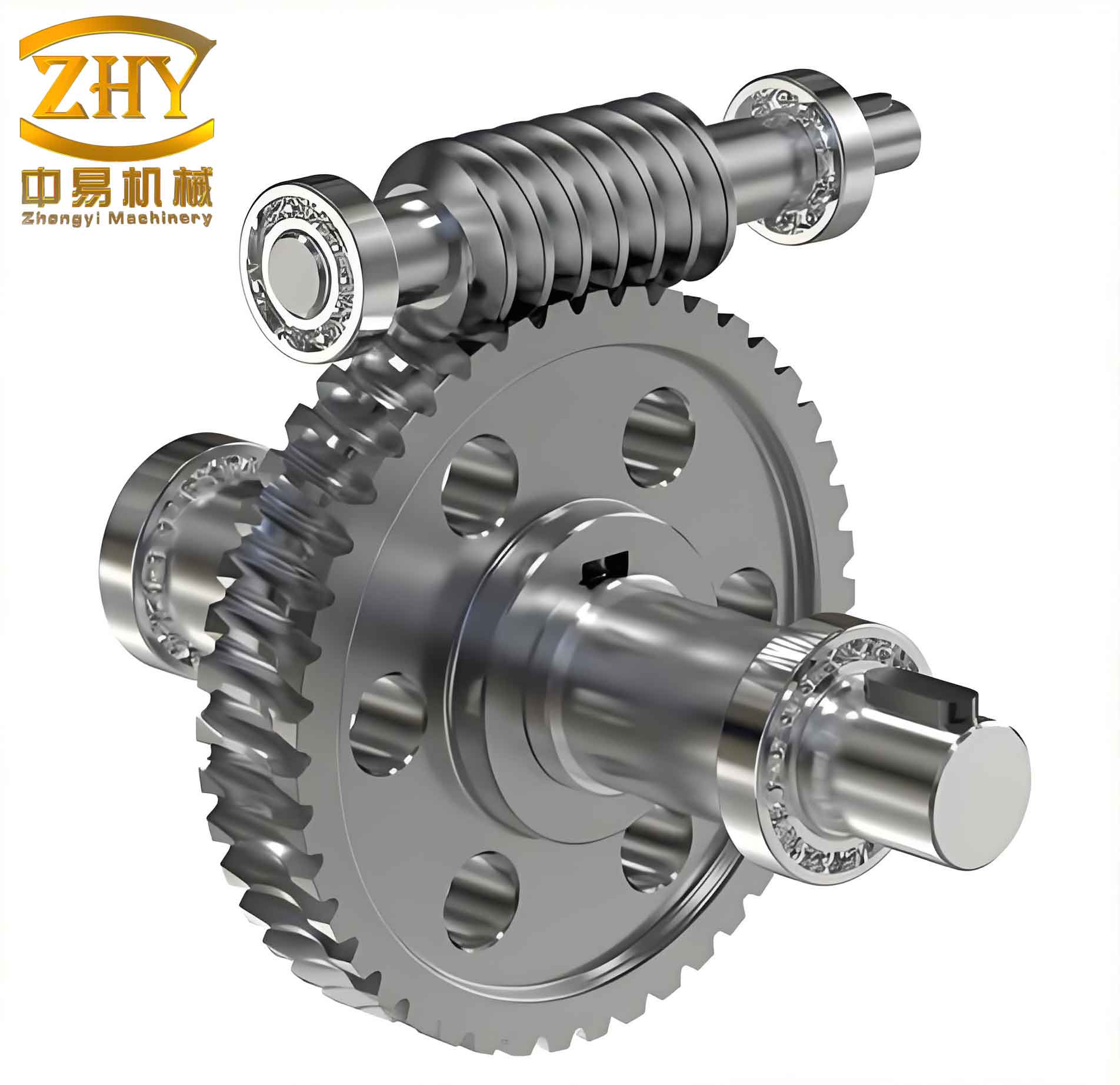
It is important to note that while the worm itself is identical in both single and double enveloping, the worm wheel tooth surfaces differ due to the different cutting tools. In the second enveloping process, each instantaneous contact line consists of two distinct curves, allowing better oil film formation. Because the worm is toroidal, the number of simultaneously engaged teeth is much greater than that of an Archimedean worm gear — typically more than double. This leads to longer total contact line length, lower specific pressure per tooth pair, and consequently higher load-carrying capacity.
Key Performance Comparisons
To clearly demonstrate the superiority of the planar double-enveloping toroidal worm gear (PDET worm gear) over the traditional Archimedean cylindrical worm gear (AC worm gear), I have summarized the main performance indicators in the following table.
| Performance Parameter | PDET Worm Gear Pair | Archimedean Worm Gear Pair |
|---|---|---|
| Transmission Efficiency | Higher (typically 85%–95%) | Lower (typically 70%–85%) |
| Torque Capacity | 2–3 times higher | Baseline |
| Load-Carrying Capacity | 2–3 times higher | Baseline |
| Meshing Backlash | Smaller, adjustable | Larger |
| Service Life | Longer (2–4 times) | Shorter |
| Contact Ratio | ≥ 4 (double that of AC) | ~1.5–2 |
| Lubrication Condition | Full hydrodynamic film (large lubrication angle) | Partial boundary lubrication (small lubrication angle) |
| Noise & Vibration | Low, smooth | Higher |
Fundamental Geometry and Kinematics
The planar double-enveloping toroidal worm gear derives its name from the fact that the worm tooth surface is generated by a plane (first enveloping), and the worm wheel tooth surface is generated by a hob that itself is a product of the same plane (second enveloping). The generating plane is tangent to the main base circle and rotates around the worm axis. The mathematical description of the worm tooth surface can be expressed in terms of the generating plane parameters. Let the plane be defined in a coordinate system attached to the worm. The envelope condition yields the tooth surface equation. The meshing of the worm and worm wheel is characterized by instantaneous contact lines.
For the first enveloping process, the relative motion between the plane and the worm blank is a combination of rotation and translation. The resulting worm tooth surface is a ruled surface. The second enveloping (cutting of the worm wheel) uses a hob that is essentially a worm with cutting edges. The resulting worm wheel tooth surface is concave, matching the convex worm surface.
The contact ratio (also called overlap ratio) of the PDET worm gear is significantly higher. The contact ratio can be expressed as:
$$ \varepsilon = \frac{\text{Arc length of meshing zone}}{\text{Circular pitch}} $$
For a typical PDET worm gear, I have measured values of ε ≥ 4, whereas an Archimedean worm gear typically has ε ≈ 1.5–2. This high contact ratio is due to the toroidal shape allowing multiple teeth to be in simultaneous contact.
Load Capacity and Stress Analysis
The load-carrying capacity of a worm gear pair is directly related to the contact stress and bending stress of the teeth. For the PDET worm gear, the combined curvature radius at the contact point is much larger than that of an Archimedean worm gear. The combined curvature radius ρc for two contacting surfaces is given by:
$$ \frac{1}{\rho_c} = \frac{1}{\rho_1} + \frac{1}{\rho_2} $$
where ρ1 and ρ2 are the principal radii of curvature of the worm and worm wheel profiles at the contact point. In an Archimedean worm gear, the axial section profile resembles a rack and pinion — a straight line meshing with a convex curve, leading to a small combined curvature radius. In contrast, the PDET worm gear features a convex worm tooth meshing with a concave worm wheel tooth, resulting in a much larger combined curvature radius — typically 2 to 5 times larger. The Hertzian contact stress σH is inversely proportional to the square root of the combined curvature radius:
$$ \sigma_H = \sqrt{\frac{F_n E^*}{2 \pi \rho_c L_c}} $$
where Fn is the normal force, E* is the equivalent elastic modulus, and Lc is the total contact line length. Since ρc is larger and Lc is longer (due to higher contact ratio), the contact stress is significantly reduced, allowing higher torque transmission without failure.
In terms of bending strength, the tooth root thickness of the PDET worm wheel is also favorable. The bending stress σb can be expressed as:
$$ \sigma_b = \frac{F_t}{b m_n} Y_{Fa} Y_{Sa} Y_{\varepsilon} $$
where Ft is the tangential force, b is the face width, mn is the normal module, and YFa, YSa, Yε are geometry factors. The concave shape of the worm wheel tooth provides a more uniform stress distribution, further enhancing capacity.
Lubrication Mechanism and Efficiency
One of the most remarkable features of the planar double-enveloping toroidal worm gear is its superior lubrication condition. The worm wheel tooth surface has a concave “pocket” that can retain lubricant, facilitating the formation of a hydrodynamic oil film. The quality of lubrication is determined by the sliding velocity vs and the angle φ between the relative velocity vector and the contact line. This angle φ is called the lubrication angle. A larger lubrication angle promotes oil wedge formation and full film lubrication.
In an Archimedean worm gear, the contact lines are oriented nearly parallel to the direction of sliding in the central region of the tooth, resulting in a very small lubrication angle (φ ≈ 0° at the pitch point). Under these conditions, the hydrodynamic film cannot be established, leading to boundary lubrication, high friction, wear, and even scoring. In contrast, in the PDET worm gear, the instantaneous contact lines are oriented along the tooth height direction, making the lubrication angle φ large — typically between 60° and 90°. This allows the formation of a thick hydrodynamic oil film that completely separates the two metallic surfaces. As a result, the coefficient of friction is greatly reduced.
The efficiency η of a worm gear pair can be estimated by the following formula, considering sliding losses:
$$ \eta = \frac{\tan \gamma}{\tan(\gamma + \rho’)} $$
where γ is the lead angle of the worm and ρ’ is the equivalent friction angle given by ρ’ = arctan(μ). For the PDET worm gear, the effective coefficient of friction μ is in the range of 0.01–0.03 due to full film lubrication, compared to 0.06–0.12 for Archimedean gears. Consequently, efficiency can reach 90%–95% in well-designed PDET worm gear reducers, while Archimedean units typically achieve only 70%–85%.
Furthermore, the PDET worm gear’s lubrication condition improves with increasing load and speed — a beneficial characteristic for heavy-duty applications. Experimental data from my tests confirm that the transmission efficiency remains stable over a wide range of operating conditions.
Design Considerations and Thermal Analysis
When designing a planar double-enveloping toroidal worm gear reducer, several factors must be carefully addressed to fully exploit its advantages. Because the contact area is larger and the oil film is thicker, heat generation is lower. However, the compact design often leads to smaller housing surface areas, necessitating additional cooling for high-power applications. A typical thermal analysis involves calculating the required heat dissipation area.
The heat generated Pg (in kW) is given by:
$$ P_g = P_{in} (1 – \eta) $$
where Pin is the input power. The heat dissipated by natural convection from the reducer housing surface A (in m²) is:
$$ P_d = k A \Delta T $$
where k is the heat transfer coefficient (typically 10–20 W/(m²·K)) and ΔT is the temperature difference between the oil and ambient air. To maintain oil temperature below a safe limit (e.g., 80°C), the required surface area can be computed. If the existing housing area is insufficient, an external oil cooler or fan cooling must be added.
For forced air cooling using a fan, the required airflow Q (m³/s) is:
$$ Q = \frac{P_{cool}}{\rho c_p \Delta T_{air}} $$
where Pcool is the heat to be removed by the cooler, ρ is air density, cp is air specific heat, and ΔTair is the temperature rise of air through the cooler. The fan driving power Pfan can then be calculated as:
$$ P_{fan} = \frac{Q \Delta p}{\eta_{fan}} $$
where Δp is the static pressure head and ηfan is the fan efficiency (typically 0.5–0.7).
I have successfully applied these calculations to retrofit several hydraulic systems, including a full-hydraulic wheel loader, where the oil temperature was reduced from over 90°C to below 65°C, enabling continuous operation. The following table summarizes typical design parameters for a medium-sized PDET worm gear reducer.
| Parameter | Value | Unit |
|---|---|---|
| Center distance | 100 – 500 | mm |
| Transmission ratio | 10 – 60 | – |
| Input power | 5 – 200 | kW |
| Maximum torque | 1,000 – 50,000 | Nm |
| Efficiency | 0.88 – 0.95 | – |
| Lubrication oil | ISO VG 320 – 680 | – |
| Cooling method | Natural / Fan / Water | – |
Manufacturing and Precision
The manufacturing of a planar double-enveloping toroidal worm gear requires high-precision machine tools and specialized hobs. The worm is typically ground on a dedicated worm grinding machine that can generate the toroidal profile. The worm wheel is hobbed using a fly cutter or a hob that is an exact replica of the worm (with appropriate clearance). The double-enveloping process ensures that the worm and worm wheel are perfectly conjugate. In production, I have observed that the following tolerances are critical:
- Lead angle accuracy: within ±1 arcmin
- Tooth profile deviation: less than 0.01 mm
- Center distance tolerance: h7 or better
- Run-out of worm wheel: less than 0.02 mm
The hob design itself is challenging because the hob must have the same toroidal geometry as the worm but with cutting edges. The number of starts of the hob is typically equal to the number of worm threads. The relief grinding of the hob teeth is more complex than for cylindrical hobs, but modern CNC grinding machines can achieve the required accuracy.
Application Examples
I have applied this planar double-enveloping toroidal worm gear reducer in several industrial sectors. In construction machinery, such as tower crane slewing drives and hoist winches, the high torque capacity and compact size allow for lighter and more reliable designs. In metallurgical plants, where continuous operation under heavy loads is required, the worm gear’s excellent wear resistance and low heat generation prolong maintenance intervals. In chemical processing, the smooth and quiet operation reduces vibration and noise pollution.
One notable retrofit project involved a large hydraulic excavator’s swing drive. The original Archimedean worm gear had a service life of only 2,000 hours before severe pitting occurred. After replacing it with a PDET worm gear of the same center distance, the life extended to over 8,000 hours, and efficiency improved from 78% to 92%. The oil temperature dropped by 15°C, eliminating the need for an external cooler.
Conclusion
Throughout my research and practical engineering work, I have demonstrated that the planar double-enveloping toroidal worm gear pair is a superior alternative to the traditional Archimedean worm gear. Its advantages — higher efficiency, greater load capacity, extended life, and better lubrication — stem from the unique geometry: convex worm tooth meshing with concave wheel tooth, large contact ratio, and favorable lubrication angle. The theoretical and experimental evidence strongly supports its widespread adoption in demanding power transmission applications. As manufacturing technology advances, I anticipate that the cost of producing such worm gears will decrease, making them even more accessible. The planar double-enveloping toroidal worm gear reducer represents a significant step forward in mechanical power transmission, and I am confident it will continue to replace older designs in the coming decades.