
In my years of experience in industrial maintenance and precision measurement, I have often encountered the challenge of assessing worn or damaged worm gear pairs. One particular type that appears frequently in metallurgical, mining, and hoisting equipment is the Archimedean cylindrical worm gear, also known as the ZA type. This gear set transmits motion and power between staggered axes, offering high transmission ratios, compact structure, and relatively simple manufacturing. However, when a worm gear fails, accurate measurement becomes critical for replacement or repair. In this article, I share my systematic approach to measuring Archimedean cylindrical worm gears, drawing from practical field work and standard specifications.
The entire measurement process requires careful attention to axial geometry, tooth profile, and center distance. I will first explain how to identify an Archimedean worm gear, then detail the measurement of key parameters such as tooth profile angle, axial module, lead angle, and finally the matching worm wheel. Throughout, I emphasize the importance of using robust formulas and data tables to minimize errors. As a practical illustration, I include a real-world case from a sawing machine. Before diving into the details, let me place a representative image of a worm gear set at the core of our discussion.
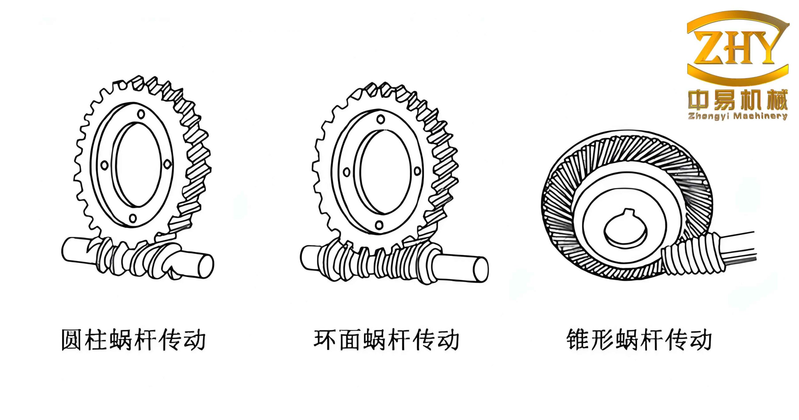
1. Identifying the Archimedean Cylindrical Worm Gear
The first step in any measurement is to confirm the type of worm gear. An Archimedean worm gear is characterized by straight axial tooth profiles. In practice, I use a simple steel ruler placed along the axial direction of the worm. If the ruler fits closely against the tooth flank, it indicates that the tooth profile is straight in the axial section, a distinctive feature that differentiates it from involute or other types of worms. This quick check saves time and guides subsequent parameter selection.
2. Measuring the Tooth Profile Angle (α)
The tooth profile angle of an Archimedean worm gear is typically standardized. According to Chinese standard GB 10085—1988, the axial tooth profile angle α is 20° for most applications. However, I have encountered modules with 14.5° or 15° in older imperial designs. I measure this angle using a universal bevel protractor or a dedicated tooth profile template. For instance, if a template with α = 20° matches the axial tooth flank closely, I confirm the angle. Alternatively, I can use the lathe’s cross-slide angle or a standard sample. The table below summarizes common tooth profile angles for different systems.
| System | Tooth Profile Angle α (axial) |
|---|---|
| Metric module (standard) | 20° |
| Metric module (old or special) | 14.5° |
| Diametral pitch (DP) | 14.5° or 20° |
3. Measuring the Axial Module (m)
Once the angle is known, I measure the axial pitch. Using a steel ruler or a pitch gauge along the worm’s tooth crest, I measure multiple pitches (e.g., 10 pitches) to improve accuracy. The axial module is then calculated by:
$$ m = \frac{\sum p_x}{n \cdot \pi} $$
where ∑p_x is the total measured pitch over n teeth. If the calculated module does not match standard metric values, I convert it to diametral pitch using:
$$ DP = \frac{25.4}{m} $$
To illustrate, during a recent measurement of a sawing machine worm, I measured 5 pitches covering 40 mm, yielding m = 40/(5 × π) ≈ 2.546 mm, which is close to standard 2.5 mm (after rounding). The table below lists common standard modules for reference.
| Module (m) | 1 | 1.25 | 1.6 | 2 | 2.5 | 3.15 | 4 | 5 | 6.3 | 8 | 10 |
|---|
4. Determining the Lead Angle (γ) and Pitch Diameter
The lead angle γ is a critical parameter for worm gear geometry. I first measure the worm’s tip diameter da1 using a micrometer or caliper. Then, for a worm with z1 threads (number of starts), the lead angle is derived from:
$$ \tan \gamma = \frac{m z_1}{d_{a1} – 2 m} $$
In the standard GB 10085—1988, the worm diameter coefficient q is defined, but in practice, many older or custom worms do not follow it. Therefore, I always compute γ from actual measurements. The pitch diameter d1 is then:
$$ d_1 = \frac{m z_1}{\tan \gamma} $$
For example, in my sawing machine case, z1 = 2, m = 2.5 mm, da1 = 55 mm, leading to tan γ = (2.5×2)/(55 – 2×2.5) = 5/50 = 0.1, so γ ≈ 5.71°. Pitch diameter d1 = 5/0.1 = 50 mm.
5. Measuring the Worm Wheel
For the worm wheel, I first measure the center distance between the worm and wheel shafts on a surface plate. This is critical because it reveals whether the wheel is modified (profile shifted) or standard. If the measured center distance ameas equals:
$$ a = \frac{d_1 + d_2}{2} = \frac{m}{2} \left( \frac{z_1}{\tan \gamma} + z_2 \right) $$
then the wheel has no modification. Here d2 = m z2 is the wheel pitch diameter. If ameas differs, the profile shift coefficient x2 can be calculated as:
$$ x_2 = \frac{2 a_{meas} – (d_1 + d_2)}{2 m} $$
All other parameters, such as helix angle (equal to worm lead angle), tooth height, and root diameters, follow standard gear formulas. The table below summarizes the key measured and derived parameters from my sawing machine example.
| Parameter | Symbol | Value |
|---|---|---|
| Worm threads | z1 | 2 |
| Wheel teeth | z2 | 34 |
| Axial module | m | 2.5 mm |
| Profile angle | α | 20° |
| Worm tip diameter | da1 | 55 mm |
| Worm lead angle | γ | 5.71° |
| Worm pitch diameter | d1 | 50 mm |
| Wheel pitch diameter | d2 | 85 mm |
| Measured center distance | ameas | 76 mm |
| Standard center distance | a | 67.5 mm |
| Profile shift coefficient | x2 | +3.4 |
6. Practical Considerations and Error Sources
When measuring worm gears, especially worn ones, I pay attention to several potential pitfalls. First, the axial pitch measurement should be performed on unworn sections if possible. Multiple measurements across at least five pitches reduce random error. Second, for the tooth profile angle, I verify with both the ruler and template methods because wear can distort the flank. Third, center distance measurement requires accurate alignment of the worm and wheel axes on the surface plate. I use height gauges and V-blocks to ensure parallelism.
I also incorporate redundancy: after calculating m from the worm, I double-check by measuring the wheel’s tip diameter and tooth count. If the values are inconsistent, I re-inspect. The following table summarizes typical measurement tolerances I apply in practice.
| Parameter | Typical Tolerance | Instrument |
|---|---|---|
| Axial pitch (over 5 pitches) | ±0.05 mm | Steel ruler / vernier caliper |
| Tip diameter | ±0.02 mm | Micrometer |
| Center distance | ±0.01 mm | Height gauge / CMM |
| Profile angle | ±0.5° | Template / protractor |
7. Detailed Case Study: Measuring a Worn Worm Gear Pair
I now present a complete example from a broken sawing machine. The original worm gear pair was severely worn, but I needed to produce a replacement. I followed the steps described above. First, I identified the worm as Archimedean type by the straight axial profile. Using a 20° template, the fit was excellent, confirming α = 20°. Then, I measured 5 axial pitches totaling 40 mm, giving m = 2.546 mm ≈ 2.5 mm (standard). The worm had 2 starts, tip diameter 55 mm, so γ = arctan(5/50) ≈ 5.71°.
Next, I measured the worm wheel. Its tooth count was 34, and I measured the center distance as 76 mm. The computed standard center distance for a non-modified pair would be (50 + 2.5×34)/2 = (50 + 85)/2 = 67.5 mm. The difference indicated a large profile shift. Using the formula:
$$ x_2 = \frac{2 \times 76 – (50 + 85)}{2 \times 2.5} = \frac{152 – 135}{5} = 3.4 $$
Thus, the wheel was heavily modified. With this data, I was able to design a new worm wheel that matched the existing worm and center distance. The entire measurement process took about two hours but ensured a proper fit.
8. Advanced Measurement Techniques for Worm Gears
In modern workshops, coordinate measuring machines (CMM) provide higher accuracy for worm gear measurement. However, I often use conventional methods because they are portable and cost-effective. For instance, when measuring coaxiality of a short shaft with two worm gear segments (like a stepped worm), I sometimes replace the coaxiality measurement with a straightness assessment of the axis, as shown in the original text. But this is a side technique; the core focus remains on the worm gear itself.
Another advanced approach is to measure the combined profile of the worm and wheel using a master gear or a functional gauge. While not always available, such gauges directly verify the transmission accuracy. In my experience, the parameters derived from pitch, diameter, and center distance are sufficient for most maintenance tasks.
9. Conclusion and Recommendations
Through years of measuring Archimedean cylindrical worm gears, I have developed a reliable workflow: identify type, measure axial module, profile angle, lead angle, and then verify with worm wheel center distance and profile shift. The formulas and tables presented here serve as a practical guide for engineers and technicians. Always remember that the worm gear’s axial straightness defines its Archimedean nature, and accurate pitch measurement is the foundation. By following this method, I have successfully restored many worn worm gear pairs, saving both time and cost.
I encourage readers to document their measurements systematically and cross-check results. In the future, I hope to see more standardization in worm gear measurement, especially for non-metric systems. For now, the combination of simple tools, careful calculation, and experience remains the most effective approach for on-site worm gear inspection.