
With the continuous development of space technology, a large amount of space production, processing, assembly, maintenance, and repair tasks need to be completed. Using robots equipped with end-effector manipulators can greatly reduce the cost and risk of astronauts performing dangerous work. Therefore, research on robot end-effector manipulators helps to improve performance, reduce implementation difficulty, and enhance reliability. Typical transmission mechanisms for robot end-effector manipulators include harmonic reducers, nut-screw mechanisms, and planetary reducers. Although worm gearing has the advantages of compact size, large reduction ratio, and self-locking capability, the space environment is characterized by high and low temperatures, high vacuum, strong radiation, and severe vibrations. All components used in the space environment must undergo space environmental adaptability analysis before launch to obtain their performance under space conditions. The worm gear pair has perpendicular axes and different materials, making the center distance sensitive to thermal expansion and contraction. Moreover, vibration and impact affect the life of the worm gear, and the assembly and lubrication of related components such as shafts and bearings involve many steps, greatly limiting the application of worm gears in space environments. Only through detailed analysis and research on the space environmental adaptability of worm gears can disasters be avoided. We conducted space environmental adaptability research on a robot end-effector manipulator developed based on the worm gear pair, analyzed the test results, and drew conclusions, exploring the general laws of worm gear application in space.
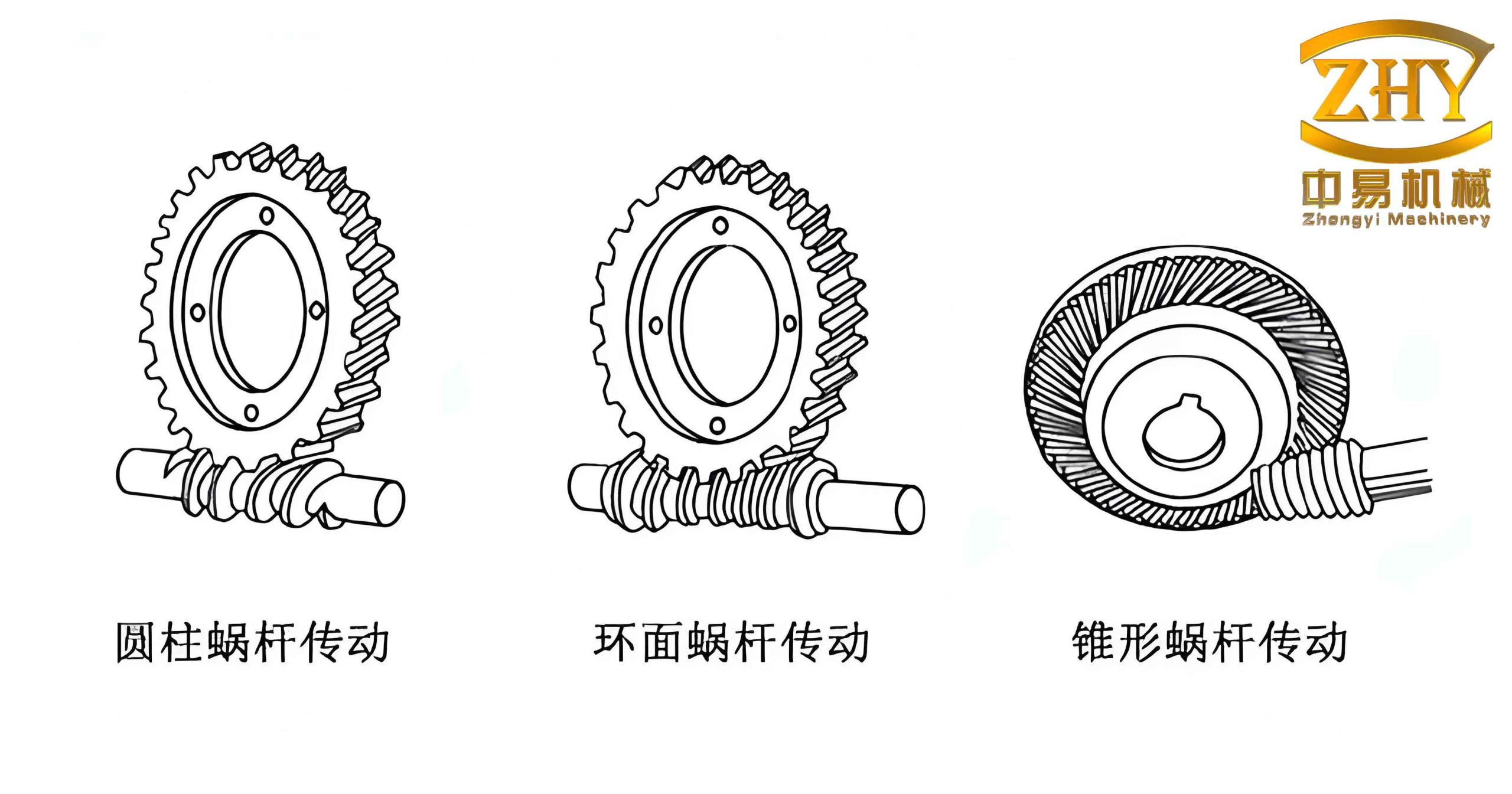
Worm Gear Application Analysis
The manipulator adopts a common clamping structure, where the finger movement is a symmetrical opening and closing motion. Therefore, the worm gear transmission mechanism uses a single worm driving two worm wheels, as illustrated in the conceptual design. The worm axis is the main axis of the manipulator, and the two worm wheels are placed symmetrically on the left and right sides. The space robot end-effector manipulator is located at the robot tip for capture and docking operations. It experiences severe temperature variations and vibration impacts, making it one of the harshest operating conditions in the robot system. Therefore, we focused on the change in center distance caused by thermal expansion and contraction and the impact of vibration on life. In addition, related lubrication and sealing need to withstand temperature changes and operate reliably under harsh temperature environments.
Design and Check of Worm Gear
Spacecraft and their payloads are usually launched into orbit by rockets, and there are severe vibration conditions during the launch process. In the space environment, the designed worm gear pair must not only have sufficient contact strength and bending strength but also meet the vibration requirements during the launch process. To prevent rust, the worm material is 9Cr18 with local carburizing hardness HRC50, and the worm wheel material is QSn6.5. Let m=1, d1=14, nominal center distance 32 mm, output torque T2 = N·m. Through checking, the actual contact stress of the worm gear is 166 MPa, which is less than the allowable contact stress of 234 MPa. The safety factor for tooth root bending fracture is 2.74, greater than the safety factor under general working conditions. In the anti-vibration design, to simplify the strength check, we introduced two assumptions: first, the worst case is when there is no locking device for the worm gear; second, the collision of the worm gear tooth surfaces caused by launch vibration is approximately equivalent to the backlash impact caused by reverse rotation of the worm gear. According to experimental verification, set the sinusoidal vibration acceleration of the worm wheel shaft as G, the load mass on the worm wheel as M, and the distance from the center of mass to the worm wheel shaft as l. Then during launch, the impact force F_impact on the worm wheel from the finger is:
$$
F_{\text{impact}} = \frac{M G l}{R} = \frac{2 M G l}{m_i}
$$
where R is the worm wheel pitch radius and m_i is the module. Additionally, let the vibration frequency be f and the vibration time be T; then the number of impacts n is:
$$
n = f T
$$
Thus, we can use the worm gear contact strength check formula to verify whether the worm gear pair still has the required contact fatigue life after launch vibration.
Center Distance Design and Analysis
In the space environment, there is no air, so outward heat transfer can only be achieved through thermal radiation. Due to the limitations of thermal radiation, the heat generated by friction cannot be conducted into the housing or surrounding environment in time. Simultaneously, thermal cycling exacerbates temperature non-uniformity, which has a great impact on system performance. The worm gear in space operates under vacuum, and heat is mainly transferred through internal conduction and radiation. Therefore, the temperature gradient at different positions of the worm gear is large. Taking the worm gear studied as an example, the maximum temperature difference between the worm wheel bearing seat and the worm wheel shaft is nearly 50°C. Hence, sufficient allowance for the normal backlash of the worm gear must be reserved during design to prevent seizure under special conditions.
Let the single-side clearance between the worm wheel bearing and the worm wheel bearing seat be XLZW; the single-side clearance between the bearing and the worm wheel shaft be XLZN; the coaxiality deviation of the worm wheel shaft be XLZ; the single-side clearance between the worm wheel and the worm wheel shaft be XLLZ; and the coaxiality deviation between the worm wheel bore and the worm wheel pitch circle be XLL. Therefore, the center distance deviation caused by worm wheel machining and assembly is:
$$
X_L = X_{LZW} + X_{LZN} + X_{LZ} + X_{LLZ} + X_{LL} \tag{1}
$$
Similarly, let the single-side clearance between the worm bearing and the worm bearing seat be XGZW; the single-side clearance between the bearing and the worm shaft be XGZN; the coaxiality of the worm shaft be XGZ. Then the center distance deviation caused by worm machining and assembly is:
$$
X_G = X_{GZW} + X_{GZN} + X_{GZ} \tag{2}
$$
Under temperature variations, the worm gear shafting undergoes thermal expansion and contraction. Due to different materials of the shafting and housing, the center distance of the worm gear changes. Generally, the worm bearing seat is connected to the motor stator and has a higher temperature than the worm; the worm wheel bearing seat is connected to the housing, which has temperature control equipment, so the worm wheel bearing seat temperature is higher than the worm wheel shaft temperature. Moreover, the materials used for the worm gear in space are typically tin bronze for the worm wheel, steel for the worm and bearings, and titanium alloy for the bearing seat. The coefficients of thermal expansion are ρcopper, ρsteel, and ρtitanium, with ρcopper > ρsteel > ρtitanium. Therefore, the increase in worm wheel center distance due to temperature is:
$$
X_{LT} = \Delta T \big[ (\rho_{\text{titanium}} – \rho_{\text{steel}}) L_W + (\rho_{\text{steel}} – \rho_{\text{titanium}}) L_N + (\rho_{\text{copper}} – \rho_{\text{titanium}}) L_Z – \rho_{\text{copper}} L \big] \tag{3}
$$
The increase in worm center distance due to temperature is:
$$
X_{GT} = \Delta T \big[ (\rho_{\text{titanium}} – \rho_{\text{steel}}) G_W – \rho_{\text{steel}} G \big] \tag{4}
$$
According to equations (1) to (4), the maximum center distance deviation caused by machining, assembly, and temperature is:
$$
X = X_L + X_G + X_{LT} + X_{GT}
$$
Therefore, the designed center distance of the worm gear should be a + X + Δa + X, where Δa is an additional safety margin determined by experimentation.
Lubrication of Worm Gear Pair
Lubrication in the space environment mainly aims to reduce friction resistance, improve motion performance, and prevent cold welding. In the low-temperature, vacuum space environment, liquid lubricants are inconvenient for worm gear pairs due to sealing difficulties; ordinary greases have problems of solidification or evaporation, so only low-temperature greases can be used. Although solid lubrication is still widely used for space moving parts, it is mainly applied to bearings, and whether it can be used for worm gear pairs needs verification. Therefore, adopting a reasonable lubrication method is an important part of worm gear research in space. In this study, we used worm gear efficiency as an evaluation index for lubrication. After running-in with MoS2 vacuum sputtered solid lubrication, we observed the tooth surface and found that the solid lubricating film was severely worn. For example, the black MoS2 thin film was worn off. Efficiency testing on worm gears lubricated with Shell MP5 grease showed extremely low efficiency at low temperatures, and stall occurred when the temperature dropped below -15°C. Braycote 601 grease performed successfully in high and low temperature tests, and the measured efficiency ranged from 16% to 38%. Experiments proved that using Braycote 601 grease lubrication is suitable for worm gear drives in space environments. For the worm and worm wheel supports, we used MoS2 solid lubricated rolling bearings.
Sealing of Worm Gear Pair
Since there is an incompatibility between grease and bearing solid lubricating film, we installed labyrinth seals at six locations with relative rotation in the worm gear compartment (two at the worm, two each at the two worm wheel shafts). The labyrinth seal requires sufficiently small radial and axial clearances, yet it must not cause scraping or increased friction under various temperature ranges. Let the coaxiality deviation of the housing be YK; the labyrinth assembly clearance be YJ; the labyrinth coaxiality deviation be YM; the coaxiality deviation of the worm wheel shaft be YZ; the labyrinth bore tolerance be YTM; and the shaft tolerance be YTZ. Therefore, the radial deviation caused by machining and assembly is:
$$
Y_L = X_{LZW} + X_{LZN} + Y_K + Y_J + Y_M + Y_Z + Y_{TM} + Y_{TZ} \tag{5}
$$
Since the labyrinth is made of aluminum alloy, the maximum reduction in labyrinth clearance caused by low temperature is:
$$
Y_{LT} = \Delta T (\rho_{\text{aluminum}} – \rho_{\text{titanium}}) L_M \tag{6}
$$
According to equations (5) and (6), the maximum radial deviation caused by machining, assembly, and temperature is:
$$
Y = Y_L + Y_{LT}
$$
Therefore, the designed labyrinth bore diameter should be D + Y + ΔD + Y, where D is the shaft diameter.
Space Environmental Verification of Worm Gear
To verify the rationality of the end-effector manipulator design based on the worm gear pair, we conducted vibration and thermal vacuum tests on the manipulator. By comparing parameters before and after the tests, we assessed whether the worm gear performance meets the design requirements.
Vibration Test
The vibration test used a vibration table to simulate the launch vibration conditions and test the performance of the worm gear pair and the end-effector manipulator. To accurately reproduce the launch conditions, the test input conditions were common vibration frequencies and amplitudes during launch. Table 1 shows the vibration input conditions.
| Frequency Range (Hz) | Vibration Amplitude | Longitudinal | Transverse | Sweep Rate |
|---|---|---|---|---|
| 10–20 | Displacement | 8.44 mm | 7.03 mm | — |
| 20–100 | Acceleration | 13.5 g | 11.25 g | — |
| 100–200 | Acceleration | 16.2 g | 13.5 g | 4 dB/oct |
Thermal Vacuum Test
The thermal vacuum test examined the adaptability of the worm gear pair to different temperature environments and, through several days of continuous operation, verified whether the worm gear pair has the mechanical properties and life consistent with the design. Figure 4 in the original paper (not shown here) illustrates the thermal vacuum life test input profile. The test cycle included high temperature (+63°C) and low temperature (-40.7°C) dwells, with performance measurements taken at various positions.
Test Results
Before and after the vibration test and the thermal vacuum test, we measured the worm gear efficiency under different loads as an indicator of worm gear life and mechanical performance. The efficiency values before the tests were slightly lower than those after the tests, but the difference was small. In fact, the efficiency even improved slightly after the tests, indicating that the worm gear pair was not damaged during the mechanical tests and the repeated motion in the high-low temperature environment. The thermal vacuum test verified the adaptability of the worm gear pair to different temperature environments. Table 2 shows the starting PWM values at different positions measured during high and low temperature phases. The values were close to those at room temperature, indicating good temperature adaptability of the gripper.
| Sequence | Temperature (°C) | Direction | Position 1 | Position 2 | Position 3 | Position 4 | Position 5 |
|---|---|---|---|---|---|---|---|
| 1 | 63 | Forward | -55 | -55 | -55 | -60 | – |
| Reverse | – | +60 | +75 | -75 | +60 | ||
| 2 | -39.5 | Forward | -35 | -35 | -35 | -35 | – |
| Reverse | – | +35 | +35 | +40 | +35 | ||
| 3 | 60.9 | Forward | -60 | -55 | -75 | -75 | – |
| Reverse | – | +75 | +55 | +60 | +60 | ||
| 4 | -40.7 | Forward | -35 | -35 | -35 | -35 | – |
| Reverse | – | +40 | +40 | +40 | +40 | ||
| 5 | 25 | Forward | -60 | -65 | -60 | -60 | – |
| Reverse | – | +65 | +75 | +55 | +75 |
Furthermore, we compared the efficiency curves before and after the vibration and thermal vacuum tests. The worm gear efficiency before the tests (lower curve) and after the tests (upper curve) showed that the efficiency remained essentially the same or even improved, confirming that the worm gear pair suffered no damage from the mechanical and thermal cycling.
Conclusion
Through research and analysis of the worm gear pair, we solved several key issues for its application in the space environment. After experimental verification, the following conclusions can be drawn:
- The mechanical analysis, thermal analysis, and assembly integration approach for the worm gear pair are correct and feasible. It is possible to design a worm gear pair that meets the severe conditions of vibration, high/low temperature, and vacuum.
- The supporting bearings, lubrication, and labyrinth seals used with the worm gear have space environmental adaptability and can meet life requirements.
- A larger backlash reduces the transmission accuracy of the worm gear but does not aggravate worm gear wear during vibration.
- The single-worm double-worm wheel structure is implementable and can achieve highly symmetric motion, meeting the grasping requirements of space end-effector manipulators.
Our study confirms that with careful design and testing, the worm gear can be a reliable and compact transmission solution for space manipulator end-effectors. Future work may focus on optimizing the worm gear profile and lubrication methods to further improve efficiency and life under space conditions.