
When I developed the parametric drawing software for worm gear components, my primary goal was to create a system that could directly serve production needs while adhering to the strict dimensional and annotation requirements of engineering drawings. The complexity of worm gear geometry—with its helical threads, varying module, lead angles, and multiple cross‑sectional views—demanded a robust, modular approach. In this article, I share the core techniques that made this possible, focusing on how to achieve reliable, adjustable dimensioning and efficient graphic block handling in a parametric environment.
Throughout the design, the term worm gear appears repeatedly because every subroutine, every coordinate calculation, and every annotation strategy is tailored to the unique features of the worm and its mating gear. The methods described here are not limited to worm gears; they can be adapted to any parametric drawing task, but I will always keep the worm gear example in the foreground.
Parametric Drawing Workflow
The entire process of generating a worm gear drawing from user‑supplied parameters follows a clear, repeatable sequence. I established this flow to ensure that all geometric and textual elements update consistently when the input parameters change. The major steps are summarized in Table 1.
| Step | Description | Key Operations |
|---|---|---|
| 1 | Input known parameters | Module, number of threads, pressure angle, center distance, etc. |
| 2 | Calculate basic dimensions of the worm gear | Pitch diameter, root diameter, addendum, dedendum, length of worm, etc. |
| 3 | Compute coordinates of all essential points | Profile points for worm thread, gear tooth profile, hub, keyway, etc. |
| 4 | Store coordinates in arrays | Organize data into arrays (e.g., X(), Y()) for efficient handling. |
| 5 | Invoke parametric drawing subroutines | Call functions for lines, arcs, hatching, dimensioning, and text. |
| 6 | Build a data file for the drawing | Generate a command file (e.g., DXF‑like or proprietary format). |
| 7 | Write instructions to the command file | Translate geometry and annotations into graphic commands. |
| 8 | Execute the drawing package | Load the command file into the graphic system and plot the finished drawing. |
This workflow is highly modular. Each step can be debugged independently, and the entire chain can be re‑executed whenever the user changes any of the worm gear parameters. For instance, increasing the module automatically recalculates all tooth proportions and updates the drawing without manual intervention.
Supporting Software for Parametric Drawing
The worm gear drawing software was built on top of a general‑purpose graphics package (referred to here as PACK) combined with a dedicated parametric drawing package (called PARA‑PACK). The base PACK did not natively support parametric capabilities—it expected fixed coordinates in its command files. To bridge this gap, I (together with my team) developed the PARA‑PACK, which provides a set of subroutines written in the same language as the host application. These subroutines act as an interface between the computational logic and the graphic kernel.
Table 2 lists the core subroutines available in PARA‑PACK that are especially relevant for worm gear drawing.
| Subroutine | Purpose | Parameters (examples) |
|---|---|---|
DIM_LINE |
Draw a linear dimension between two points | Point1, Point2, leader position, value, tolerance, decimal places |
DIM_ANGLE |
Dimension the angle between two lines | Line endpoints, arc location, degree/minute/second values |
DRAW_ARROW |
Draw an arrow from tail to head | Head point, tail point, arrowhead style |
TEXT |
Place a text string at a specified position | Position, height, rotation angle, justification, string |
BLOCK_SAVE |
Save a group of entities as a named block | Base point, block name, window coordinates |
BLOCK_INSERT |
Insert a previously saved block at a given location | Block name, insertion point, scale, rotation |
With these tools, I could write parametric programs that perform geometric calculations in a high‑level language (e.g., FORTRAN or BASIC) and then issue calls to PARA‑PACK to produce the actual drawing. The user never needs to see the low‑level graphic instructions.
Key Parametric Drawing Techniques
The most challenging aspect of parametric drawing for worm gears is ensuring that dimensions, annotations, and auxiliary symbols (like arrows for radii or diameters) remain legible and correctly placed when the geometry changes. Over the course of this project, I developed and refined several techniques to handle these issues.
Maintaining Relative Stability of Dimension Positions
To prevent dimensions from scattering or overlapping when the worm gear parameters vary, I adopted a consistent reference‑based approach. All dimensions are anchored to a common baseline or datum. For example, when dimensioning the worm’s thread length, root diameter, and pitch, all distances are measured from a fixed axial reference (e.g., the leftmost end face of the worm). This guarantees that as the worm length grows or shrinks, the dimension lines move uniformly as a group without collapsing or crossing each other.
Let me illustrate with a typical worm gear section. Suppose we have four dimensions along the worm axis: $$A$$ (total length), $$B$$ (threaded portion), $$C$$ (undercut), and $$D$$ (chamfer). If all these dimensions reference the same vertical datum line (say $$x=0$$), then the positions of their leader lines are computed relative to that datum. When $$A$$ increases, every other dimension shifts proportionally, preserving the overall layout.
Table 3 shows the relationship used in my program to compute the y‑coordinates of dimension lines for a worm gear.
| Dimension | Expression for Leader y‑coordinate | Datum |
|---|---|---|
| Total length | $$y_{\text{total}} = y_0 + \Delta_{\text{total}}$$ | $$y_0$$ is the baseline offset |
| Threaded portion | $$y_{\text{thread}} = y_0 + \Delta_{\text{thread}}$$ | |
| Undercut | $$y_{\text{undercut}} = y_0 + \Delta_{\text{undercut}}$$ | |
| Chamfer | $$y_{\text{chamfer}} = y_0 + \Delta_{\text{chamfer}}$$ |
The offsets ($$\Delta$$ values) are computed from the worm gear geometry and stored in a vector that is recalculated whenever parameters change. All leader lines then move together, avoiding the chaotic shifts that would occur if each dimension was placed independently.
Ensuring Correct Dimension Positions
Even with a good layout, the subroutines like DIM_LINE automatically decide where to place the dimension text—either above, below, left, or right of the dimension line. For a complex worm gear drawing with many dimensions, this automatic placement can lead to text overlapping or crossing extension lines. To overcome this, I developed a “erase‑and‑rewrite” technique.
First, the program calls DIM_LINE to draw the dimension line and extension lines, but it suppresses the numeric text (by passing a null or special flag). Then it uses a low‑level command to erase only the last drawn entity (the text). After that, I call a generic TEXT subroutine to place the dimension value exactly where the design intent requires, using absolute coordinates relative to the worm gear’s datum.
For example, to mark the root diameter of a worm, the code might look like this (pseudocode):
CALL DIM_LINE(P1, P2, P3, VALUE, NDEC, NCODE, DLOW, DHIGH)  ' draw dimension line, no text
ERASE_LAST          ' remove the auto‑placed number
CALL TEXT(X, Y, HEIGHT, ANGLE, JUST, VALUE, NDEC, NCODE, DLOW, DHIGH)  ' re‑insert text at desired location
The parameters X, Y are carefully chosen to avoid neighbouring dimensions. For a worm gear, I often place the root diameter text inside the thread profile, and the outside diameter text just above the crest.
Dimensioning Angles with Precision
On worm gear drawings, angles such as the lead angle or pressure angle need to be dimensioned with degrees, minutes, and seconds. The DIM_ANGLE subroutine can draw the arc and produce the angle value, but it may not always place the text in the desired quadrant. Again, I employ the erase‑and‑rewrite method. For instance, to dimension the lead angle $$\lambda$$ of a worm:
CALL DIM_ANGLE(P1, P2, P3, P4, DEG, MIN, SEC)  ' draw arc and text
ERASE_LAST
CALL TEXT(X, Y, H, 0.0, 2, 'λ = 45° 30′ 20″')
I also developed a specialized subroutine to format the angle text with a tolerance (e.g., $$45^\circ \pm 0.5^\circ$$). The tolerance string is built programmatically and passed to TEXT as a single string.
Arrow Drawing for Radii and Diameters
Worm gear drawings frequently require arrows pointing to fillet radii or to the tip of a thread for diameter annotations. I created a dedicated arrow‑drawing subroutine, DRAW_ARROW, that takes the head and tail coordinates. The head is the point where the arrow touches the geometry, and the tail is the point where the dimension line starts. An example call for dimensioning the tip diameter of a worm gear is:
CALL DRAW_ARROW(XHEAD, YHEAD, XTAIL, YTAIL)
CALL TEXT(XTAIL+DX, YTAIL+DY, H, 0, 1, 'Φ 50.0')
The coordinates are computed from the geometry of the worm gear cross‑section. Table 4 lists the typical arrow parameters used in the program.
| Feature | Head point location | Tail point location |
|---|---|---|
| Root radius (worm) | At the fillet midpoint | Offset perpendicular to the profile |
| Tip diameter (worm gear) | On the addendum circle | Outside the tooth profile, aligned radially |
| Keyway width | Inside the hub slot | Outside hub, with leader line |
Block Handling for Complex Entities (Hatching, Repeated Profiles)
One of the most tedious tasks in worm gear drawings is adding cross‑hatching—for example, to indicate the section of the worm shaft or the gear blank. Hatching across the complex tooth profile can be extremely time‑consuming if done with individual line segments. To solve this, I implemented a block‑based technique using two subroutines: BLOCK_SAVE and BLOCK_INSERT.
The idea is simple: first draw a simple geometric shape (say, a square or a circle) and fill it with hatching. Then save the entire entity set (geometry + hatching) as a named block. Later, when the worm gear assembly requires a hatched area, I can insert this block at the exact location, scale, and rotation needed.
For instance, to create a hatched cross‑section of a worm gear tooth, I would:
- Move the drawing origin to the center of the tooth space.
- Draw a square of side equal to the tooth space width, and fill it with the required hatch pattern.
- Call
BLOCK_SAVE(XBASE, YBASE, XWIN1, YWIN1, XWIN2, YWIN2, 'TOOTH_HATCH')to save the hatched square as a block. - Erase the temporary square.
- For each tooth space in the worm gear, call
BLOCK_INSERT('TOOTH_HATCH', XINS, YINS, SCALE, ANGLE).
This technique drastically reduces the number of graphic commands and makes the program much faster. It also ensures consistent hatching quality across all identical features.
Another application is in drawing the worm’s helical thread profile. The thread shape repeats along the axis, but with slight variations at the ends. I save a single thread profile (including dimension annotations) as a block, then insert it multiple times with appropriate shifts and rotations. This modularity is particularly beneficial for worm gears with multiple starts.
Practical Example: Drawing a Worm Gear Assembly
To demonstrate the combined use of all these techniques, I will walk through a simplified program that draws a worm gear assembly. The goal is to generate the worm (helical thread) and the mating gear (involute teeth) with proper dimensions, arrows, and hatching.
Assume the input parameters are:
- Module $$m = 4\ \text{mm}$$
- Number of threads on worm $$z_1 = 2$$
- Number of teeth on gear $$z_2 = 30$$
- Pressure angle $$\alpha = 20^\circ$$
- Center distance $$C = \frac{m(z_1 + z_2)}{2} = 64\ \text{mm}$$
I first compute the essential dimensions:
$$d_w = m \cdot z_1 = 8\ \text{mm} \quad \text{(pitch diameter of worm)}$$
$$d_g = m \cdot z_2 = 120\ \text{mm} \quad \text{(pitch diameter of gear)}$$
$$\text{Addendum } h_a = m = 4\ \text{mm}$$
$$\text{Dedendum } h_f = 1.25m = 5\ \text{mm}$$
$$\text{Lead angle of worm } \lambda = \tan^{-1}\left(\frac{z_1 m}{\pi d_w}\right) = \tan^{-1}\left(\frac{8}{\pi \cdot 8}\right) = \tan^{-1}(0.3183) \approx 17.66^\circ$$
Next, I generate the profile points for the worm thread. The coordinates of one complete thread winding are computed as a series of points along the pitch cylinder, offset by the addendum and dedendum. These points are stored in arrays.
Drawing starts by setting a new origin at the left end of the worm. I call a series of LINE, ARC, and CIRCLE subroutines to draw the worm blank and thread. For the thread, I use a loop that repeatedly inserts the saved thread profile block along the helix path.
After the worm is complete, I move to the gear. The gear is drawn in a separate view (often a frontal view and a section view). The tooth profiles are generated by an involute geometry subroutine, and again blocks are used for identical teeth. The hatching for the gear blank is inserted via the block method described earlier.
Finally, dimensions and annotations are added. The program calls DIM_LINE for axial and radial dimensions, DIM_ANGLE for the lead angle and pressure angle, and DRAW_ARROW for radii and diameters. Every text placement is fine‑tuned with the erase‑and‑rewrite technique to avoid overlapping. The complete drawing is saved as a command file and then processed by the graphic output package.
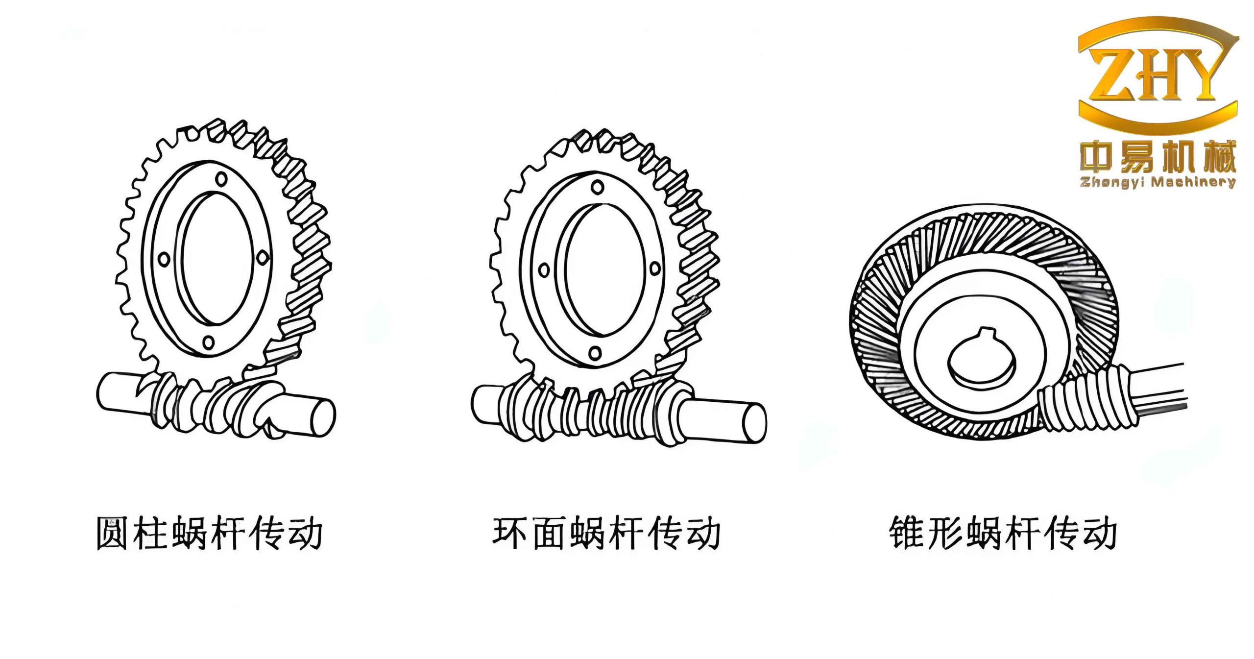
The output is a production‑ready worm gear drawing that adapts automatically to any change in module, number of teeth, or other input parameters. Over the course of this project, I found that the techniques described here—relative datum dimensioning, erase‑and‑rewrite annotation, custom arrow routines, and block‑based hatching—are indispensable for parametric drawing of worm gears. They can be extended to any mechanical component that requires flexible, reliable drafting.
Summary of Formulas Used in Worm Gear Parametric Drawing
To aid future implementation, I have collected the most frequently used formulas in my worm gear parametric program.
| Quantity | Formula |
|---|---|
| Pitch diameter of worm | $$d_w = m \cdot z_1$$ |
| Pitch diameter of gear | $$d_g = m \cdot z_2$$ |
| Center distance | $$C = \frac{d_w + d_g}{2} = \frac{m(z_1 + z_2)}{2}$$ |
| Addendum | $$h_a = m$$ |
| Dedendum | $$h_f = 1.25m$$ |
| Lead of worm | $$L = z_1 \cdot p = z_1 \cdot \pi m$$ |
| Lead angle | $$\lambda = \tan^{-1}\left(\frac{L}{\pi d_w}\right) = \tan^{-1}\left(\frac{z_1 m}{d_w}\right)$$ |
| Axial pressure angle | $$\alpha_x = \tan^{-1}\left(\frac{\tan \alpha_n}{\cos \lambda}\right)$$ |
| Normal chordal tooth thickness (worm) | $$s_n = \frac{\pi m}{2}$$ (approximately, for standard profiles) |
| Root diameter of worm | $$d_{rw} = d_w – 2h_f$$ |
| Outside diameter of worm | $$d_{aw} = d_w + 2h_a$$ |
| Root diameter of gear | $$d_{rg} = d_g – 2h_f$$ |
| Outside diameter of gear | $$d_{ag} = d_g + 2h_a$$ |
These formulas are implemented in the calculation module that feeds the parametric drawing routines. By encapsulating the worm gear geometry in a set of clean mathematical relations, the drawing software becomes easy to maintain and extend.
Conclusion
Parametric drawing of worm gears is a challenging but rewarding task. Through careful design of the workflow—from input parameters to final plot—and the development of specialized subroutines for dimension stability, text placement, arrows, and block handling, I was able to create a robust system that produces production‑quality drawings. The techniques I have presented are directly transferable to other parametric drawing projects. For anyone tackling similar problems, I recommend focusing on a strong datum‑based layout, allowing manual override of automatic placements, and leveraging block technology for repetitive elements. These principles have served me well in the world of worm gear drafting, and I hope they will help others as well.
—
Note: The worm gear images and example programs referenced in this text have been omitted to keep the focus on the technical methodology.