
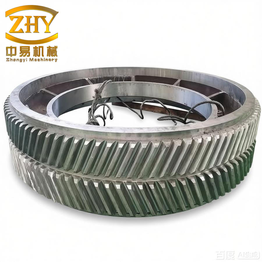
In the field of power transmission, herringbone gears are widely used due to their high load capacity, smooth meshing, and low noise characteristics. Among various tooth profiles, the double circular-arc herringbone gear has gained significant attention because of its superior contact strength and bending fatigue resistance. However, the discontinuous change in mesh stiffness during engagement can induce vibration and impact, which limits its application in high-speed and high-precision machinery. To address this issue, a novel design known as the herringbone gear with staggering tooth has been proposed. In this design, the two halves of the herringbone gear are intentionally offset by a certain axial distance, thereby altering the distribution of contact points along the tooth width and reducing the stiffness jump. This article presents a comprehensive stiffness calculation method for such herringbone gears, based on the single-point mesh stiffness derived from finite element analysis and the superposition of contact points at different axial positions.
Our research focuses on the quantitative evaluation of the mesh stiffness variation for a standard double circular-arc herringbone gear (GB12759-91) with staggering tooth. We will first analyze the meshing characteristics, then establish the stiffness calculation model, and finally compare the stiffness jump values with those of a conventional herringbone gear without staggering. The results demonstrate that the staggering tooth design effectively reduces the amplitude of stiffness fluctuation, which is beneficial for mitigating vibration and noise in herringbone gear systems.
1. Meshing Characteristics of Herringbone Gear with Staggering Tooth
Let us denote the single-side tooth width of the double circular-arc herringbone gear as B, the axial pitch as Px, and the fractional part of the contact ratio representing the axial width as Δb. The axial distance between two contact points on the same tooth is defined as qta, while the axial distance between the convex and concave contact points of adjacent teeth is denoted as q′ta. Depending on the relationship among these parameters, the entire meshing process can be divided into four cases: (a) Δb ≤ q′ta, (b) q′ta < Δb ≤ Px/2, (c) Px/2 < Δb ≤ qta, and (d) Δb > qta. For brevity, we only analyze the first case, Δb ≤ q′ta, which is commonly encountered in practical herringbone gear designs.
In the meshing analysis, we consider a series of axial positions along the tooth width. The whole gear engagement cycle can be divided into eight intervals (denoted as I to VIII) according to the number of simultaneously contacting points and the number of meshing tooth pairs. For the staggering tooth herringbone gear, the number of meshing points varies as 6-5-4-5-6-5-4-5, and the number of meshing tooth pairs varies as 4-4-3-4-4-4-3-4. In contrast, for a conventional herringbone gear without staggering, the pattern is 6-4-6-4 for points and 8-6-8-6 for tooth pairs. The detailed axial distances from the front face of the gear for each boundary point (1 to 24 and 1′ to 24′) are listed in Table 1.
| Point | Axial distance (mm) | Point | Axial distance (mm) |
|---|---|---|---|
| C1 | Px/2 + qta | C1′ | Px |
| C2 | B | C2′ | Px/2 + Δb + q′ta |
| C3 | Px/2 | C3′ | Px + Δb |
| C4 | q′ta + Δb | C4′ | qta |
| C5 | Px/2 + Δb | C5′ | Px/2 + Δb |
| C6 | q′ta + Px/2 | C6′ | qta + Δb |
| C7 | Px | C7′ | Px |
| C8 | Px/2 + Δb + q′ta | C8′ | Px/2 + qta |
| C9 | B | C9′ | B |
| C10 | qta − Px/2 | C10′ | 0 |
| C11 | Δb | C11′ | Px/2 − qta + Δb |
| C12 | Δb + qta − Px/2 | C12′ | Δb |
| C13 | Px/2 | C13′ | q′ta |
| C14 | qta | C14′ | Px/2 |
| C15 | Δb + Px/2 | C15′ | B − qta |
| C16 | qta + Δb | C16′ | Px/2 + Δb |
| C17 | Px | C17′ | Px/2 + q′ta |
| C18 | Px/2 + qta | C18′ | Px |
| C19 | 0 | C19′ | 0 |
| C20 | Px/2 + Δb − qta | C20′ | qta − Px/2 |
| C21 | Δb | C21′ | Δb |
| C22 | Px − qta | C22′ | qta − Px/2 + Δb |
| C23 | Px/2 | C23′ | Px/2 |
| C24 | 0 | C24′ | qta |
From the meshing analysis, it is evident that as the gear rotates, the number of engaged points and tooth pairs changes abruptly at specific positions, leading to a discontinuous variation of the mesh stiffness of the herringbone gear. The frequency of this variation is given by f = zn/60, where z is the number of teeth and n is the rotational speed in rpm. The staggering tooth design redistributes the contact pattern and reduces the stiffness jump magnitude.
2. Calculation Method for Mesh Stiffness of Herringbone Gear
The overall mesh stiffness of the herringbone gear at any instant is obtained by summing the individual single-point stiffness values of all contact points that are simultaneous active. Therefore, the key step is to accurately compute the single-point mesh stiffness as a function of the axial position along the tooth width.
2.1 Single-Point Stiffness of Double Circular-Arc Profile
Based on extensive finite element calculations and nonlinear regression for the GB12759-91 double circular-arc gear (as reported in the literature), the relationship between the dimensionless comprehensive deformation ω̄ and the applied normal load Fn at any theoretical meshing point can be expressed as:
$$
\bar{\omega} = \rho \alpha_i \left[ \frac{F_n \rho}{M_n^2 E’} \right]^{\beta_i}, \quad i = 1,2,3
$$
where ω̄ = ω / Mn (ω is the maximum comprehensive deformation, Mn is the normal module), ρ̄ is the relative curvature coefficient, E′ is the equivalent elastic modulus, and b is the axial coordinate variable along the tooth width. The parameters αi and βi depend on the region of the tooth width where the load is applied:
Region 1 (near the front face, 0 < b ≤ 2Mn):
$$
\alpha_1 = (b + 1.88)\left[0.3462(b + 1.88) – 0.4183\right]^{-1}
$$
$$
\beta_1 = (b + 0.49)\left[1.1278(b + 0.49) + 0.2081\right]^{-1}
$$
Region 2 (middle of tooth, 2Mn < b ≤ B − 2Mn):
$$
\alpha_2 = 3.0873, \quad \beta_2 = 0.8797
$$
Region 3 (near the rear face, B − 2Mn < b ≤ B):
$$
\alpha_3 = (b – B + 4.224)\left[0.3465(b – B + 4.224) – 0.4439\right]^{-1}
$$
$$
\beta_3 = 0.80936 – 0.0033(b – B)
$$
Setting ω̄ = 1 (i.e., unit deformation), we solve for Fn, which numerically equals the single-point mesh stiffness Kj(b):
$$
K_j(b) = F_{n,j} = \left( \frac{E’ M_n^{2\beta_i – 1}}{\alpha_i^{\beta_i} \rho^{\beta_i – 1}} \right)^{1/\beta_i}
$$
In the above equation, the subscript j indicates that this single-point stiffness contributes to the total stiffness in the interval where j simultaneous contact points exist. The value of Kj(b) is a function of the axial distance b measured from the front face of the herringbone gear.
2.2 Superposition of Stiffness for the Herringbone Gear with Staggering Tooth
Based on the meshing analysis and the defined boundary points (Table 1), we establish a coordinate system with the origin at the left end of meshing interval I. The mesh position variable x (in mm) increases along the axial direction. By summing the single-point stiffness of all active contact points within each interval, we obtain the total mesh stiffness functions for the eight intervals K1(x) through K8(x).
Interval I (0 < x ≤ Px/2 − qta + Δb):
$$
\begin{aligned}
K_1(x) = & K_{2A}(C1 + x) + K_{2T}(C3 + x) + K_{3A}(C10 + x) \\
& + K_{1’T}(C1′ + x) + K_{2’A}(C4′ + x) + K_{2’T}(C10′ + x)
\end{aligned}
$$
Interval II (Px/2 − qta + Δb < x ≤ Δb):
$$
\begin{aligned}
K_2(x) = & K_{2T}(C3 + x) + K_{3A}(C10 + x) + K_{1’T}(C1′ + x) \\
& + K_{2’A}(C4′ + x) + K_{2’T}(C10′ + x)
\end{aligned}
$$
Interval III (Δb < x ≤ Px − qta):
$$
\begin{aligned}
K_3(x) = & K_{2T}(C3 + x) + K_{3A}(C10 + x) \\
& + K_{2’A}(C4′ + x) + K_{2’T}(C10′ + x)
\end{aligned}
$$
Interval IV (Px − qta < x ≤ Px/2):
$$
\begin{aligned}
K_4(x) = & K_{2T}(C3 + x) + K_{3A}(C10 + x) + K_{2’A}(C4′ + x) \\
& + K_{2’T}(C10′ + x) + K_{3’A}(C19′ + x – q’_{ta})
\end{aligned}
$$
Interval V (Px/2 < x ≤ q′ta + Δb):
$$
\begin{aligned}
K_5(x) = & K_{2T}(C3 + x) + K_{3A}(C10 + x) + K_{3T}(C19 + x – P_x/2) \\
& + K_{2’A}(C4′ + x) + K_{2’T}(C10′ + x) + K_{3’A}(C19′ + x – q’_{ta})
\end{aligned}
$$
Interval VI (q′ta + Δb < x ≤ Px/2 + Δb):
$$
\begin{aligned}
K_6(x) = & K_{2T}(C3 + x) + K_{3A}(C10 + x) + K_{3T}(C19 + x – P_x/2) \\
& + K_{2’T}(C10′ + x) + K_{3’A}(C19′ + x – q’_{ta})
\end{aligned}
$$
Interval VII (Px/2 + Δb < x ≤ Px/2 + q′ta):
$$
\begin{aligned}
K_7(x) = & K_{3A}(C10 + x) + K_{3T}(C19 + x – P_x/2) \\
& + K_{2’T}(C10′ + x) + K_{3’A}(C19′ + x – q’_{ta})
\end{aligned}
$$
Interval VIII (Px/2 + q′ta < x ≤ Px):
$$
\begin{aligned}
K_8(x) = & K_{3A}(C10 + x) + K_{3T}(C19 + x – P_x/2) \\
& + K_{4A}(C24 + x – P_x/2 – q’_{ta}) \\
& + K_{2’T}(C10′ + x) + K_{3’A}(C19′ + x – q’_{ta})
\end{aligned}
$$
In the above expressions, the subscripts A and T denote the concave (A) and convex (T) flanks of the tooth, respectively. The numbers 1, 2, 3, 4 indicate the specific tooth index. By substituting the actual gear parameters into these functions, we can compute the instantaneous mesh stiffness of the herringbone gear with staggering tooth at any rotation angle.
3. Calculation Example
We consider a double circular-arc herringbone gear with the following parameters: single-side tooth width B = 70 mm, axial pitch Px = 63.1129 mm, and overlap fraction Δb = 6.85 mm. The modulus Mn = 6 mm, and the equivalent elastic modulus E′ = 2.06 × 10⁵ MPa. Using the formulas above and the single-point stiffness relationships, we computed the mesh stiffness values at the boundaries of the eight intervals for both the staggering tooth herringbone gear and a conventional herringbone gear without staggering. The results are summarized in Tables 2 and 3.
| Point No. | Axial distance 1 (mm) | Stiffness 1 (kN/mm) | Axial distance 2 (mm) | Stiffness 2 (kN/mm) | Absolute difference (kN/mm) | Relative difference (%) |
|---|---|---|---|---|---|---|
| 1 | 63.1129 | 2068.87 | 0.06311 | 2530.0 | 461.13 | 22.32 |
| 2 | 5.9326 | 2756.16 | 5.995 | 3234.85 | 478.69 | 17.37 |
| 3 | 6.879 | 3202.54 | 6.942 | 2487.59 | −714.95 | −28.74 |
| 4 | 12.812 | 2623.23 | 12.875 | 1907.67 | −715.56 | −27.28 |
| 5 | 31.556 | 2068.87 | 31.620 | 2530.7 | 461.83 | 22.32 |
| 6 | 37.4891 | 2756.16 | 37.4892 | 3234.85 | 478.69 | 17.37 |
| 7 | 38.436 | 3202.54 | 39.50 | 2487.59 | −714.95 | −28.74 |
| 8 | 44.3684 | 2623.23 | 44.4035 | 1907.67 | −715.56 | −27.28 |
| Point No. | Axial distance 1 (mm) | Stiffness 1 (kN/mm) | Axial distance 2 (mm) | Stiffness 2 (kN/mm) | Absolute difference (kN/mm) | Relative difference (%) |
|---|---|---|---|---|---|---|
| 1 | 63.1129 | 2218.166 | 0.06311 | 3141.826 | 923.66 | 41.64 |
| 2 | 5.9326 | 3592.754 | 5.995 | 4550.134 | 357.38 | 26.65 |
| 3 | 6.879 | 4485.511 | 6.942 | 3055.604 | −1429.9 | −31.88 |
| 4 | 12.812 | 3326.845 | 12.875 | 1895.766 | −1431.079 | −43.1 |
From Tables 2 and 3, it is clear that the maximum absolute stiffness jump for the herringbone gear with staggering tooth is 715.56 kN/mm, whereas for the conventional herringbone gear it reaches 1431.079 kN/mm — exactly twice the value of the staggering case. The relative jump (percentage) for the staggering herringbone gear is at most 28.74%, compared to 43.1% for the non-staggering design. This reduction of about 10 percentage points in relative stiffness variation and a halving of the absolute jump amplitude are significant improvements for the dynamic behavior of herringbone gear transmissions.
4. Discussion
The reduction in stiffness fluctuation directly contributes to lower vibration and noise levels during operation. In the conventional herringbone gear, the simultaneous engagement and disengagement of entire tooth pairs cause sudden changes in the total contact points, leading to impulsive forces. By introducing an axial offset (staggering tooth), the contact pattern is spread more evenly over the meshing cycle. The number of points changes more gradually (6-5-4-5-6-5-4-5) compared to the step-like 6-4-6-4 pattern of the non-staggered herringbone gear. Consequently, the resulting mesh stiffness of the herringbone gear becomes smoother, reducing the excitation to the gear dynamic system.
It is worth noting that the stiffness calculation method presented here is based on the assumption of linear elasticity and the empirical single-point stiffness formula derived from finite element analyses. The results are valid for the specific standard tooth profile (GB12759-91) and the given geometry. For other designs of herringbone gears, the coefficients αi and βi may need to be recalibrated. Nevertheless, the overall approach — dividing the meshing cycle into intervals and superposing single-point stiffness — is generally applicable to any herringbone gear with staggering tooth.
Another important aspect is the influence of the staggering amount (the axial offset) on the stiffness variation. In our example, the offset is determined by the pre-specified design parameters. Optimizing the offset value could further minimize the stiffness jump, but that is beyond the scope of this article. The current analysis provides a fundamental tool for predicting the mesh stiffness of herringbone gears with staggering tooth, which can be used for subsequent vibration analysis, noise prediction, and structural optimization.
5. Conclusion
In this study, we have developed a complete procedure for calculating the mesh stiffness of a double circular-arc herringbone gear with staggering tooth. The key contributions are summarized as follows:
- The meshing process of the herringbone gear with staggering tooth is categorized into eight distinct intervals based on the axial positions of contact points. The number of active meshing points and tooth pairs varies in a controlled pattern.
- A single-point stiffness formula for the double circular-arc profile is adopted, with piecewise coefficients depending on the axial location (near the front face, middle, and near the rear face).
- By summing the individual stiffness values of all simultaneously engaging points, the total mesh stiffness functions for each interval are derived analytically.
- A numerical example for a typical herringbone gear (B=70 mm, Px=63.1129 mm, Δb=6.85 mm) shows that the maximum stiffness jump of the staggering tooth design is only half of that observed in the conventional herringbone gear. The relative stiffness variation is reduced from 43.1% to 28.74%.
Therefore, the herringbone gear with staggering tooth exhibits significantly improved stiffness continuity, which is beneficial for reducing vibration, impact, and noise in high-performance gear systems. The method presented here lays a solid foundation for further dynamic analysis and practical design of herringbone gears in industrial applications.