
Hypoid gears are widely recognized for their high contact ratio, smooth transmission, strong load-carrying capacity, and flexible spatial arrangement. These advantages have made them indispensable in automotive drivelines, mining machinery, electric tools, and many other staggered-shaft applications. In recent years, the demand for miniaturized, high-speed, and low-energy gear drives has led to increased interest in single-stage large-ratio transmissions. Hypoid gears with a small number of pinion teeth and high speed ratios can maintain high efficiency while providing a large transmission ratio, making them an attractive alternative to worm gears and planetary gear systems.
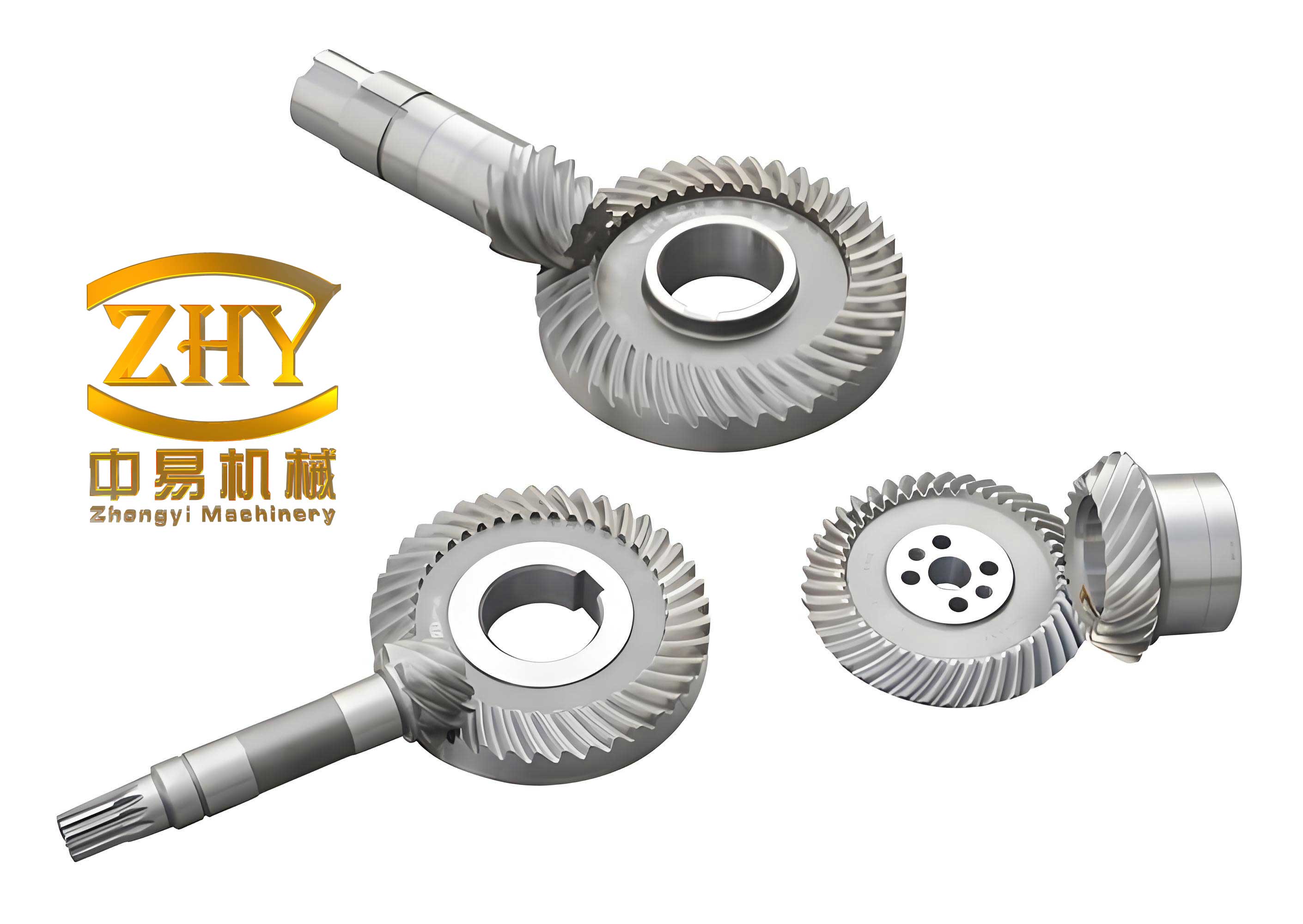
In this work, I focus on hypoid gears with only 2 to 4 pinion teeth and speed ratios ranging from 10 to 30. The study covers geometric parameter design, root and interference checks, tooth surface equation derivation, three-dimensional modeling, and experimental cutting. The key challenge lies in avoiding undercutting, tooth tip narrowing, and machining interference when the pinion tooth count is extremely low. By combining radial and tangential modification, appropriate pressure angles, spiral angles, and face widths, these problems can be effectively resolved. I will present the theoretical development, numerical simulation, and experimental verification of such hypoid gears.
Geometric Design and Analysis
The design of hypoid gears with few teeth and high speed ratios is more complex than conventional designs. For a small pinion tooth number, the risk of undercutting and tooth tip narrowing increases significantly. In addition, the face cone angle of the gear tends to approach 85°, which may cause interference with the cutter head during machining. Therefore, several geometric constraints must be considered simultaneously.
First, the minimum number of pinion teeth for no undercutting is related to the equivalent number of teeth. For a pinion with spiral angle β1m, the equivalent number can be approximated by:
$$z_{v1} \approx \frac{z_1}{\cos^3 \beta_{1m}}$$
To avoid undercutting, the equivalent tooth number should not be less than 20. This implies that a relatively large spiral angle is necessary when the pinion has only a few teeth.
The tooth top width is another critical factor. The cutter tip width W2 for the gear (obtained by the forming method) can be expressed as:
$$W_2 = s_{n1} – (h_{f2} – h_{f1})(\tan \alpha_{f1} + \tan \alpha_{f2})$$
where sn1 is the normal tooth thickness at the pinion pitch point, hf2 and hf1 are the root heights of the gear and pinion, and αf1 and αf2 are the pressure angles on the two sides of the gear tooth. The pinion tooth top width b1 should also be checked using the involute interference condition.
Another practical constraint is the minimum slot width at the inner end of the pinion. This value should be kept above 0.4 mn to ensure proper cutting conditions. Similarly, the face cone angle of the gear should be limited to 85° to avoid interference with the cutter head. These constraints guide the selection of the basic geometric parameters.
Determination of Pitch Cones
For hypoid gears with a shaft angle of 90°, the position of the pitch point is determined by the gear pitch radius r2, the pinion spiral angle β1, and the pinion offset angle η. The gear pitch radius is influenced by the face width b2 and the location of the design point along the face width. To increase design flexibility, a face width coefficient kb2 is introduced:
$$r_2 = \frac{d_2 – k_{b2} b_2 \sin \delta_2}{2}$$
where d2 is the outer diameter of the gear, δ2 is the gear pitch angle, and kb2 is typically 0.5 for the midpoint design. The initial gear pitch angle can be estimated from:
$$\tan \delta_2′ = \frac{\sin \Sigma}{\frac{z_2}{z_1} + \cos \Sigma} \times \frac{1}{1.2}$$
In this work, I set the shaft angle Σ = 90°, gear rotation right-hand, pinion left-hand, with a pinion offset downward. The pinion spiral angle is chosen based on the constraints described above. For example, in the 4:41 case, β1 was set to 59°.
To balance the tooth shapes on both flanks, a limit pressure angle coefficient falim is introduced. The limit pressure angle αlim and the limit curvature radius ρlim are computed using the gear geometry. These values directly affect the local conjugate characteristics of the tooth surfaces.
Blank Dimension Calculation
The blank dimensions of the gear are calculated first. The outer cone distance Re is:
$$R_e = \frac{d_2}{2 \sin \delta_2}$$
The working depth h at the midpoint is approximated by:
$$h = \frac{r_2}{z_2} \cdot \frac{1}{\cos \beta_2}$$
The whole tooth depth hm includes a clearance c:
$$h_m = h + c$$
where c ≈ 0.15h + 0.05. The gear addendum and dedendum are:
$$h_{a2} = h_{f2} \quad \text{(for equal addendum design)}$$
$$h_{f2} = 1.15 h – h_{a2} + 0.05$$
The gear face angle δa2 and root angle δf2 are then:
$$\delta_{a2} = \delta_2 + \theta_{a2}, \quad \delta_{f2} = \delta_2 – \theta_{f2}$$
where θa2 and θf2 are the addendum and dedendum angles. The outer addendum and dedendum are then determined by the corresponding angles and the cone distance.
After the gear blank is determined, the pinion blank is obtained by considering the gear face cone as the pinion root cone, and vice versa. The pinion addendum and dedendum are:
$$h_{a1}’ = h – h_{f2} + c, \quad h_{f1}’ = h – h_{a2} + c$$
The pinion face angle is calculated from the gear root angle and the offset angle εf:
$$\sin \delta_{a1}’ = \cos \epsilon_f \sin \delta_{f2}’ \cos \Sigma + \sin \delta_{f2}’ \sin \Sigma$$
These formulas allow the complete blank geometry of both members to be computed.
Undercutting and Interference Checks
Since the pinion may have as few as 2 teeth, it is essential to perform undercutting checks. The method compares the actual height modification coefficient with the minimum or maximum allowable value. For the pinion, the minimum height modification coefficient is:
$$x_{hm \min 1} = \frac{1.1 \sin \alpha_{n}}{2 m_{n}} + \frac{k_{hapx} – x_{hx1}}{m_n}$$
where khapx is the tool addendum coefficient at the check point, and xhx1 is the local height modification coefficient. For the 4:41 design, the calculation gives xhm1 = 1.53 and xhmmin1 = 0.83, so the pinion is safe from undercutting.
For the gear, a similar check is performed. The maximum height modification coefficient is:
$$x_{hm \max 1} = \frac{1.1 \sin \alpha_{n}}{2 m_{n}} + \frac{k_{hapx}}{m_n} – x_{hx2}$$
In the 4:41 example, xhmmax1 = 1.26, and the actual value is 1.53, which satisfies the condition xhm1 > xhmmax1. Thus the gear does not undercut either.
Interference between the gear tooth tip and the pinion tooth root (fillet interference) is also checked. The condition for the pinion is:
$$\frac{\tan \alpha_{f1}’ + \tan \alpha_{f2}’}{z_{v1}} \le \frac{\sin \alpha_n}{2} \left( \frac{4}{z_{v1}} – \frac{x_{h1}}{z_{v1}} \right)$$
Similar expressions are used for the gear. These checks ensure that the meshing process does not involve the non-involute portions of the tooth profiles.
Force Analysis
To ensure stable meshing, the axial and radial forces must push the gear members apart rather than pulling them together. The tangential force on the gear is:
$$F_{mt2} = \frac{2000 T_2}{d_{m2}}$$
The tangential force on the pinion is related by:
$$F_{mt1} = F_{mt2} \frac{\cos \beta_{m2}}{\cos \beta_{m1}}$$
The axial force on the pinion (driving side) is:
$$F_{ax1D} = F_{mt1} \left( \frac{\tan \alpha_{nD}}{\cos \beta_{m1}} \sin \delta_1 + \frac{\sin \beta_{m1}}{\cos \beta_{m1}} \cos \delta_1 \right)$$
Similarly, the radial force is:
$$F_{rad1D} = F_{mt1} \left( \frac{\tan \alpha_{nD}}{\cos \beta_{m1}} \cos \delta_1 – \frac{\sin \beta_{m1}}{\cos \beta_{m1}} \sin \delta_1 \right)$$
For the 4:41 design, with a gear torque T2 = 50 N·m, the calculated forces are Fax1D = 1740.56 N, Fax2D = 814.13 N, Fax1C = -1576.5 N, and Fax2C = 598.63 N. The positive signs indicate separating forces, which is desirable.
Orthogonal Analysis of Key Geometric Parameters
To identify the most influential geometric parameters on the pinion pitch angle, I performed an orthogonal trial design. Four factors were considered: spiral angle (A), cutter diameter (B), tooth depth coefficient (C), and addendum coefficient (D). Each factor was assigned three levels, as shown in Table 1.
| Level | Spiral angle (A) [°] | Cutter diameter (B) [mm] | Tooth depth coeff. (C) | Addendum coeff. (D) |
|---|---|---|---|---|
| 1 | 56 | 82.9 | 2.5 | -0.1 |
| 2 | 59 | 88.9 | 3.0 | 0.0 |
| 3 | 62 | 94.9 | 3.5 | 0.1 |
Using a standard L9 orthogonal array, the pinion pitch angle and midpoint tooth tip thickness were computed for each combination. The results are summarized in Table 2.
| Run | A | B | C | D | Pitch angle [° ′ ″] | Midpoint tooth tip thickness [mm] |
|---|---|---|---|---|---|---|
| 1 | 1 | 1 | 1 | 1 | 7°28′40″ | 1.911 |
| 2 | 1 | 2 | 2 | 2 | 6°42′24″ | 1.526 |
| 3 | 1 | 3 | 3 | 3 | 6°02′01″ | 1.177 |
| 4 | 2 | 1 | 2 | 3 | 7°31′22″ | 1.719 |
| 5 | 2 | 2 | 3 | 1 | 6°34′56″ | 0.978 |
| 6 | 2 | 3 | 1 | 2 | 5°45′42″ | 2.027 |
| 7 | 3 | 1 | 3 | 2 | 7°36′11″ | 1.269 |
| 8 | 3 | 2 | 1 | 3 | 6°25′13″ | 2.098 |
| 9 | 3 | 3 | 2 | 1 | 5°24′14″ | 1.564 |
The range analysis shows that factor B (cutter diameter) has the largest influence on the pinion pitch angle, followed by A (spiral angle), D (addendum coefficient), and C (tooth depth coefficient). The optimal combination from this trial was A1B1C3D2. Therefore, the proper selection of cutter diameter and spiral angle is crucial for the successful design of hypoid gears with few teeth and high speed ratios.
Design Example
Based on the above methodology, I designed a pair of hypoid gears with a tooth ratio of 4:41. The basic blank parameters are listed in Table 3.
| Parameter | Gear | Pinion |
|---|---|---|
| Number of teeth | 41 | 4 |
| Face width [mm] | 20 | |
| Outer addendum [mm] | 0.236 | — |
| Outer dedendum [mm] | 5.247 | — |
| Outer whole depth [mm] | 5.483 | 5.647 |
| Pitch angle [°] | 81.877 | 6.582 |
| Face angle [°] | 82.100 | 10.669 |
| Root angle [°] | 76.915 | 6.402 |
| Offset [mm] | 30 | |
| Pitch diameter [mm] | 120 | — |
| Mean pressure angle [°] | 22.5 | |
| Shaft angle [°] | 90 | |
| Mean spiral angle [°] | — | 59 |
| Hand of spiral | Right | Left |
The constraint checks confirmed that the pinion equivalent tooth number is approximately 45 (above the minimum of 20), the gear face angle is below 85°, and the minimum slot width is 2.804 mm, well above the limit of 0.8 mm. Thus the design satisfies all geometric constraints.
Tooth Surface Equation Derivation
The tooth surface of the gear is generated by the forming method. I established the machining coordinate system shown in Figure 3.1 of the original thesis. The gear fixed coordinate system S2 is rotated by the machine root angle γm with respect to the machine coordinate system Sm. The cutter coordinate system SG is fixed to the machine. The cutter point radius is rc, and the blade angle α determines the flank direction. The position vector and normal vector of a point on the cutter surface can be written in SG as:
$$\mathbf{r}_c = \begin{bmatrix} (r_0 – u_g \sin \alpha \cos \theta_g) \\ -(r_0 – u_g \sin \alpha \sin \theta_g) \\ -u_g \cos \alpha \end{bmatrix}$$
$$\mathbf{n}_c = \begin{bmatrix} \cos \alpha \cos \theta_g \\ -\cos \alpha \sin \theta_g \\ -\sin \alpha \end{bmatrix}$$
where ug and θg are the surface parameters, and r0 is the nominal cutter radius. For the inner blade (gear convex side) α is positive; for the outer blade α is negative.
By applying coordinate transformations from SG to S2, the gear tooth surface equation is obtained:
$$x_2 = H_2 + (r_0 – u_g \sin \alpha \cos \theta_g)\cos \gamma_m \cos \gamma_m + x_{g2}\sin \gamma_m \cos \gamma_m$$
$$y_2 = V_2 – (r_0 – u_g \sin \alpha \sin \theta_g)$$
$$z_2 = x_{g2}\cos \gamma_m – (r_0 – u_g \sin \alpha \cos \theta_g)\sin \gamma_m$$
For the pinion, I used the envelope principle. The pinion tooth surface is generated as the envelope of the family of gear tooth surfaces. The coordinate transformation between the gear and pinion is established using two rotating coordinate systems S2 and S1. The relative velocity vector v(12) at the contact point must satisfy the equation of meshing:
$$\mathbf{n}_2 \cdot \mathbf{v}^{(12)} = 0$$
From the coordinate transformations, the relative velocity components are:
$$v_x^{(12)} = -y_2 – \frac{1}{i_{21}} z_2 \cos \phi_2$$
$$v_y^{(12)} = x_2 – \frac{1}{i_{21}} z_2 \sin \phi_2$$
$$v_z^{(12)} = \frac{1}{i_{21}} (x_2 \sin \phi_2 + y_2 \cos \phi_2)$$
Substituting the gear tooth surface and the normal vector into the equation of meshing yields an implicit function:
$$f(u_g, \theta_g, \phi_2) = 0$$
This equation can be solved together with the coordinate transformation to obtain the pinion tooth surface. After eliminating Φ2, the pinion surface is expressed as a function of ug and θg. The resulting tooth surface equation is lengthy and includes the offset distance E, the spiral angle, and the gear blank dimensions.
Three-Dimensional Simulation
To verify the tooth topology and detect possible undercutting or tip narrowing, I created three-dimensional solid models of both the gear and the pinion. The process involved solving the tooth surface coordinates using MATLAB and then importing the point cloud into the UG (Unigraphics) software for solid modeling.
To obtain a regular grid of surface points, I used the tooth surface rotational projection method. In the projection plane, the tooth surface is mapped to a two-dimensional region. The boundary points are computed from the outer cone distance, addendum, dedendum, face angle, and root angle. The projection coordinates (X, Y) are related to the three-dimensional coordinates (x, y, z) by:
$$X = x, \quad Y = \sqrt{y^2 + z^2}$$
For the gear, solving the nonlinear system of the tooth surface equation together with the projection relationship gives the 3D coordinates. For the pinion, the equation of meshing is added to the system. The surface is divided into 5 × 9 grid points, as shown in Figures 4.2 and 4.3 of the original thesis.
After generating the data points in MATLAB, I imported them into UG and constructed the tooth surfaces using the “through curves” and “ruled surface” commands. The tooth root surfaces were created by extending the adjacent flanks. By trimming the blank with the tooth space solid and performing a circular pattern, the complete gear pair model was obtained.
Models for 4:41, 3:60, and 2:60 Ratios
I first modeled the 4:41 design. The resulting pinion and gear models are shown in Figures 4.6 and 4.9 respectively. The tooth profiles are continuous, with no undercutting at the root and no narrowing at the tip. The tooth thickness distribution is satisfactory.
Next, I increased the speed ratio to 20 with a 3:60 design. The basic parameters are listed in Table 4. In this case, the pinion spiral angle was increased to 72° to avoid undercutting. The tooth depth coefficient was reduced to 3.4, and the addendum coefficient was kept at 0.05.
| Parameter | Gear | Pinion |
|---|---|---|
| Number of teeth | 60 | 3 |
| Face width [mm] | 20 | |
| Outer addendum [mm] | 0.143 | — |
| Outer dedendum [mm] | 3.194 | — |
| Outer whole depth [mm] | 3.337 | 3.391 |
| Pitch angle [°] | 84.005 | 5.666 |
| Face angle [°] | 84.176 | 7.386 |
| Root angle [°] | 81.250 | 4.910 |
| Offset [mm] | 30 | |
| Pitch diameter [mm] | 130 | — |
| Mean pressure angle [°] | 22.5 | |
| Shaft angle [°] | 90 | |
| Mean spiral angle [°] | — | 72 |
| Hand of spiral | Right | Left |
The 3D models showed that the pinion tooth shape remains well-formed. The longitudinal curvature is slightly larger, but no root undercutting or tip narrowing is present. This demonstrates the feasibility of a 3-pinion design.
Finally, I explored a 2:60 ratio with a pinion tooth count of 2. The key parameters are listed in Table 5. The spiral angle remained 72°, and the tooth depth and addendum coefficients were the same as in the 3:60 design. The gear face angle reached 84.431°, which is close to the 85° limit.
| Parameter | Gear | Pinion |
|---|---|---|
| Number of teeth | 60 | 2 |
| Face width [mm] | 20 | |
| Outer addendum [mm] | 0.147 | — |
| Outer dedendum [mm] | 3.293 | — |
| Outer whole depth [mm] | 3.440 | 3.492 |
| Pitch angle [°] | 84.311 | 4.938 |
| Face angle [°] | 84.431 | 7.273 |
| Root angle [°] | 81.629 | 4.835 |
| Offset [mm] | 30 | |
| Pitch diameter [mm] | 140 | — |
| Mean pressure angle [°] | 22.5 | |
| Shaft angle [°] | 90 | |
| Mean spiral angle [°] | — | 72 |
| Hand of spiral | Right | Left |
The two-tooth pinion model also exhibited a complete tooth profile without undercutting or tip narrowing. The face cone angle of the gear is close to the allowable limit, indicating that the design is near the practical boundary for a 30:1 ratio with this offset and cutter diameter. For ratios beyond 30, special attention must be paid to cutter interference and pinion strength.
Cutting Experiments
To validate the theoretical and numerical results, I performed cutting experiments on a GH-35 spiral bevel gear milling machine. The machine has been retrofitted with a three-axis numerical control system, which replaces the traditional change-gear transmission with servo drives.
Machining Parameters for the Gear
The gear was cut using the Formate (forming) method. The machining parameters for the 4:41 design are listed in Table 6. The radial cutter position S2 and angular cutter position q2 were converted to machine settings such as eccentric angle and cradle angle for the GH-35 machine.
| Parameter | Value |
|---|---|
| Workpiece mounting angle [°] | 76.915 |
| Vertical cutter position [mm] | 49.084 |
| Horizontal cutter position [mm] | 26.094 |
| Axial work offset [mm] | 44.21 |
| Cradle angle [°] | 96.242 |
| Eccentric angle [°] | 43.504 |
During the gear cutting, particular attention was paid to the clearance between the cutter head, the gear blank, and the machine bed because the gear face angle is close to 85°. The cutting was performed in several passes, and the tooth thickness was measured with a gear tooth caliper after the first complete cut.
Machining Parameters for the Pinion
The pinion was generated using the tilt method. The machining parameters are listed in Table 7. The tilt angle and swivel angle were converted to machine tool settings. Due to the small tooth count, the pinion blank was mounted with a specially designed sleeve to avoid interference between the cutter, cradle, and workpiece head.
| Parameter | Convex side | Concave side |
|---|---|---|
| Workpiece mounting angle [°] | -3.314 | -3.456 |
| Radial cutter position [mm] | 54.161 | 55.708 |
| Angular cutter position [°] | 91.204 | 83.209 |
| Axial work offset [mm] | -0.324 | 0.536 |
| Base offset [mm] | 0.077 | -0.685 |
| Vertical work offset [mm] | 27.346 | 32.046 |
| Roll ratio | 9.732 | 10.299 |
| Basic swivel angle [°] | -36.718 | -46.073 |
| Basic tilt angle [°] | 11.941 | 0.129 |
| Machine swivel angle [°] | 8.82 | 357.753 |
| Machine tilt angle [°] | 47.392 | 48.183 |
| Eccentric angle [°] | 42.333 | 43.602 |
| Cradle angle [°] | 194.67 | 196.29 |
Before cutting, the pinion machining parameters were verified by tooth contact analysis (TCA). The TCA results showed a slightly diagonal contact pattern and a nearly symmetric transmission error curve, which are acceptable for the first trial. The actual cutting tests were then performed on the GH-35 machine. The pinion was cut with a small depth increment per pass. After the concave flank was cut to full depth, the convex flank was finished by adjusting the Y-axis feed to achieve the required tooth thickness.
The photographs in the original thesis (Figures 5.3 to 5.7) show the cutting process and the finished components. The machined gear and pinion were placed in mesh, as shown in Figure 5.8. The actual tooth shapes were consistent with the three-dimensional models. No undercutting, tip narrowing, or machining interference was observed on either member.
Conclusion and Outlook
In this research, I have systematically investigated the design, simulation, and machining of hypoid gears with few teeth and high speed ratios. The main conclusions are as follows:
- I established the geometric design constraints for hypoid gears with pinion tooth numbers below 5. These constraints include undercutting, tooth tip narrowing, meshing interference, and the 85° face cone angle limit. For speed ratios above 10, both radial and tangential modifications are necessary. The orthogonal analysis revealed that cutter diameter and spiral angle are the most influential factors on the pinion pitch angle.
- I derived the tooth surface equations for both the gear and the pinion. The gear surface was obtained from the Formate cutting model, and the pinion surface was derived as the envelope of the gear surface using the equation of meshing.
- Using MATLAB and UG, I generated accurate three-dimensional models for 4:41, 3:60, and 2:60 hypoid gear pairs. The models confirmed that the pinion tooth profile remains intact even with two teeth, provided that the spiral angle and modification coefficients are properly selected.
- I successfully cut a 4:41 hypoid gear pair on a GH-35 milling machine. The machined tooth surfaces matched the theoretical models, and no undercutting or tip narrowing appeared. This verifies the feasibility of producing high-ratio hypoid gears with very few pinion teeth using conventional spiral bevel gear machines.
Future work should extend the current approach to even higher speed ratios (above 30) and pinion tooth numbers down to one. More advanced optimization methods should be employed to consider the mutual interactions between geometric parameters. In addition, the three-dimensional modeling should include realistic tooth root and tip fillets for more accurate stress analysis and contact simulation. The experimental work should be extended to include load testing and noise/vibration measurement of the gear pair.
In summary, hypoid gears with few teeth and high speed ratios are not only theoretically feasible but also practically manufacturable. This work provides a solid foundation for the application of such gears in precision indexing, servo mechanisms, and compact industrial drives. The design methodology and experimental validation will be valuable for engineers working on high-ratio hypoid gears.