
In this work I focus on the dynamic behavior of high-speed rail helical gears under different side clearances and on the modification strategies that can reduce vibration, impact, and contact stress. The helical gears used in high-speed train bogies are subjected to severe operating conditions, including high rotational speed, heavy load, and unavoidable manufacturing and assembly errors. Among these factors, the tooth side clearance, also called backlash, plays a decisive role in the meshing impact, contact pressure distribution, and fatigue life of helical gears. I established a parametric model of a helical gear pair, imported it into finite element software, and performed modal and transient dynamic analyses. Based on the obtained stress and contact pressure results, I determined reasonable modification parameters and carried out both tooth profile modification and tooth lead modification. The comparison between the unmodified and modified helical gears demonstrates that proper modification can effectively improve the transmission performance of high-speed rail helical gears.
Parametric Modeling of Helical Gears
The helical gears studied in this work are part of a high-speed rail traction system. The basic parameters are defined on the normal plane, while the geometrical dimensions are calculated on the transverse plane. The normal module, number of teeth, normal pressure angle, helix angle, tooth width, addendum coefficient, and dedendum coefficient are the primary input parameters. Table 1 lists the basic parameters of the driving pinion and the driven gear.
| Parameter | Unit | Pinion | Gear |
|---|---|---|---|
| Normal module, \(m_n\) | mm | 6 | 6 |
| Number of teeth, \(z\) | — | 35 | 85 |
| Normal pressure angle, \(\alpha_n\) | ° | 20 | 20 |
| Helix angle, \(\beta\) | ° | 17.5 | 17.5 |
| Addendum coefficient, \(h_{an}^*\) | — | 1.05 | 1.05 |
| Dedendum coefficient, \(c_n^*\) | — | 0.3 | 0.3 |
| Tooth width, \(b\) | mm | 68 | 68 |
The transverse parameters of helical gears are derived from the normal parameters through the following relationships. The transverse module is
$$ m_t = \frac{m_n}{\cos\beta} $$
The transverse pressure angle is
$$ \alpha_t = \arctan\left(\frac{\tan\alpha_n}{\cos\beta}\right) $$
The transverse addendum coefficient and dedendum coefficient are
$$ h_{at}^* = h_{an}^* \cos\beta $$
$$ c_t^* = c_n^* \cos\beta $$
The addendum and dedendum are
$$ h_a = h_{at}^* m_t = h_{an}^* m_n $$
$$ h_f = (h_{at}^* + c_t^*) m_t = (h_{an}^* + c_n^*) m_n $$
The reference diameter, addendum diameter, dedendum diameter, and base diameter are calculated as
$$ d = m_t z $$
$$ d_a = d + 2h_a $$
$$ d_f = d – 2h_f $$
$$ d_b = d \cos\alpha_t $$
Using the above formulas, I obtained the geometrical dimensions of the helical gear pair, which are summarized in Table 2.
| Item | Unit | Pinion | Gear |
|---|---|---|---|
| Reference diameter, \(d\) | mm | 220.1911 | 534.7499 |
| Addendum diameter, \(d_a\) | mm | 232.7911 | 547.3499 |
| Dedendum diameter, \(d_f\) | mm | 203.9911 | 518.5499 |
| Base diameter, \(d_b\) | mm | 205.7309 | 499.6039 |
The involute profile of the helical gears is generated from the base circle. For an arbitrary point \(K\) on the involute, the radius \(r_k\) and the pressure angle \(\alpha_k\) satisfy
$$ r_k = \frac{r_b}{\cos\alpha_k} $$
The involute function is
$$ \theta_k = \tan\alpha_k – \alpha_k $$
In the Cartesian coordinate system, the involute can be expressed as
$$ x = r_b(\cos u + u\sin u) $$
$$ y = r_b(\sin u – u\cos u) $$
The helical line on the cylindrical surface follows
$$ x = a\cos\theta, \quad y = a\sin\theta, \quad z = b\theta $$
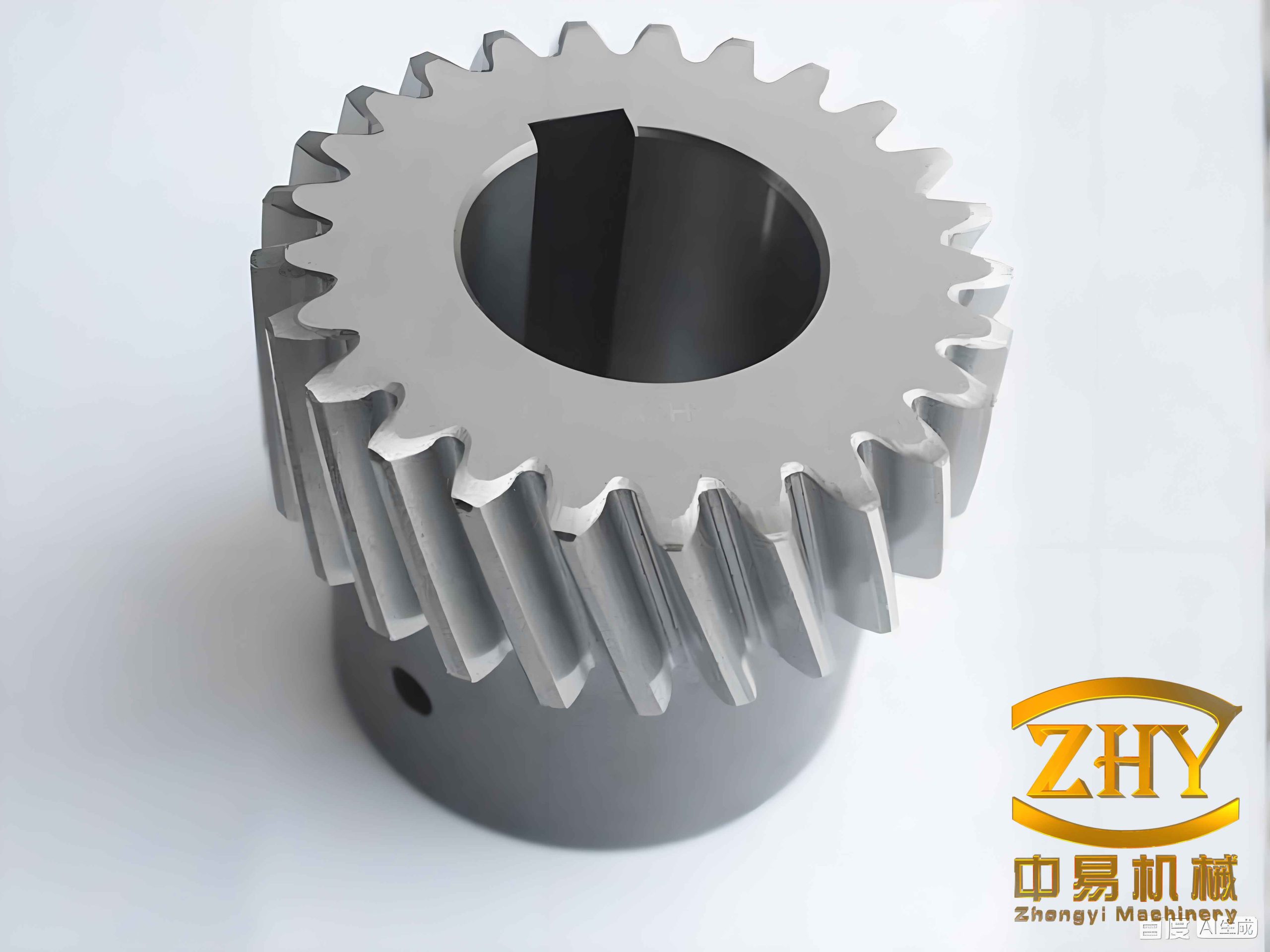
where \(a\) is the cylinder radius, \(b\) is related to the lead, and \(\theta\) is the rotation angle. Using these equations, I created the tooth profile and the helical sweep. After arraying the single tooth along the circumference, I obtained the complete three-dimensional models of the pinion and the gear. The assembly was completed by defining a gear pair constraint and adjusting the angular position to avoid interference. The assembled helical gear pair is shown in the figure below.
Side Clearance Theory for Helical Gears
The side clearance of helical gears is defined as the gap between the non-working flanks of two meshing gear teeth when the working flanks are in contact. In practice, side clearance is necessary because it compensates for manufacturing errors, assembly errors, thermal expansion, and elastic deformation, and it also provides space for lubricating oil. However, excessive side clearance leads to impact, vibration, noise, and uneven load distribution, while insufficient side clearance may cause jamming, overheating, and rapid wear. Therefore, the correct determination of side clearance is crucial for the reliable operation of helical gears.
The side clearance can be classified into three types: circumferential backlash \(j_{wt}\), normal backlash \(j_{bn}\), and radial backlash \(j_r\). The circumferential backlash is the maximum arc length by which one gear can be rotated while the other is fixed. The normal backlash is the shortest distance between the non-working flanks along the common normal. The radial backlash is the reduction in center distance required to bring the non-working flanks into contact.
The normal backlash of involute helical gears can be derived from the base circle geometry. When two working flanks contact at point \(K\), the normal backlash \(j_{bt}\) on the transverse plane is
$$ j_{bt} = e_{b2} – s_{b1} + 2(r_{b1} + r_{b2})\tan\alpha_{wt} $$
where \(e_{b2}\) is the base circle tooth space width of gear 2, \(s_{b1}\) is the base circle tooth thickness of gear 1, \(r_{b1}\) and \(r_{b2}\) are the base circle radii, and \(\alpha_{wt}\) is the working pressure angle. The working pressure angle is
$$ \cos\alpha_{wt} = \frac{r_{b1} + r_{b2}}{a_w} $$
where \(a_w\) is the center distance. The normal backlash \(j_{bn}\) is related to the transverse backlash by
$$ j_{bn} = j_{bt}\cos\beta_b $$
where \(\beta_b\) is the base helix angle. Combining these equations, the normal backlash can be written as
$$ j_{bn} = \left[ p_{bn} – (s_{bn1} + s_{bn2}) + 2(r_{b1} + r_{b2})\tan\alpha_{wt} \right]\cos\beta_b $$
It can be seen that, except for the working pressure angle, all other parameters are fixed for a given helical gear pair. Therefore, once the center distance is determined, the normal backlash of involute helical gears is a constant. The relationship between the center distance error and the side clearance is summarized in Table 3.
| Center distance (mm) | Working pressure angle (°) | Side clearance (mm) |
|---|---|---|
| 380.1 | 21.90 | 0.13 |
| 380.2 | 21.95 | 0.27 |
| 380.3 | 21.98 | 0.39 |
The main factors affecting the side clearance of helical gears include center distance error, manufacturing errors such as profile error and helix error, temperature and lubrication conditions, parallelism error of the axes, and elastic deformation under load. Among these, the center distance error is one of the most direct and controllable factors. In this study, I focused on three center distance errors: 0.1 mm, 0.2 mm, and 0.3 mm, which correspond to side clearances of 0.13 mm, 0.27 mm, and 0.39 mm, respectively.
Finite Element Modeling and Hertz Contact Theory
Before performing the finite element analysis, I applied the Hertz contact theory to estimate the contact stress of the helical gears. According to Hertz theory, the contact between two involute helical gear teeth can be simplified as the contact between two cylinders. The half-width of the contact zone is
$$ a = \sqrt{\frac{2F_{bn}}{\pi L} \frac{(1-v_1^2)/E_1 + (1-v_2^2)/E_2}{1/R_1 \pm 1/R_2}} $$
where \(F_{bn}\) is the normal load, \(L\) is the total contact line length, \(v_1\) and \(v_2\) are the Poisson’s ratios, \(E_1\) and \(E_2\) are the elastic moduli, and \(R_1\) and \(R_2\) are the equivalent curvature radii at the meshing point. The maximum contact stress is
$$ \sigma_H = \frac{2F_{bn}}{\pi a L} $$
For helical gears, the contact stress at the pitch point can be expressed as
$$ \sigma_H = Z_E Z_H Z_\beta Z_\varepsilon \sqrt{\frac{F_t}{d_1 b} \frac{u \pm 1}{u}} $$
where \(Z_E\) is the elasticity coefficient, \(Z_H\) is the zone factor, \(Z_\beta\) is the helix angle factor, \(Z_\varepsilon\) is the contact ratio factor, \(F_t\) is the tangential force, \(d_1\) is the reference diameter of the pinion, \(b\) is the tooth width, and \(u\) is the gear ratio. The values of these coefficients for the present helical gears are listed in Table 4. Substituting these values yields a theoretical contact stress of approximately 1024.3 MPa. The material of the helical gears is 20CrMoTi after surface quenching, and its allowable stress is about 1600 MPa. Therefore, the contact stress is below the allowable value, and the strength requirement is satisfied.
| Parameter | \(Z_E\) | \(Z_H\) | \(Z_\beta\) | \(Z_\varepsilon\) |
|---|---|---|---|---|
| Value | 187.66231 | 5.45825 | 0.99724 | 0.50142 |
The material properties of the helical gears are given in Table 5. The density is 7850 kg/m³, the Poisson’s ratio is 0.31, and the elastic modulus is 206 GPa. These values were assigned to both the pinion and the gear in the finite element model.
| Property | Value | Unit |
|---|---|---|
| Density | 7850 | kg/m³ |
| Poisson’s ratio | 0.31 | — |
| Elastic modulus | 206 | GPa |
For the contact algorithm, I selected the augmented Lagrange method, which combines the advantages of the penalty function method and the Lagrange multiplier method. The contact type was set as flexible-to-flexible, and the contact behavior was defined as frictional with a friction coefficient of 0.1. The tooth surfaces of the pinion were chosen as the contact surfaces, and the tooth surfaces of the gear were chosen as the target surfaces. The mesh was generated using a hex-dominant method with local refinement near the contact regions. The element size was 5 mm in the contact zone and 10 mm elsewhere. The final mesh contained 1,022,711 nodes and 221,480 elements. The boundary conditions included two rotational joints that allowed only rotation about the gear axes. A torque of 2900 N·m was applied to the driving pinion, corresponding to the starting condition of the high-speed train, and a resistive torque was applied to the driven gear. The rotational speed was calculated as 25 rad/s from the power and torque relationship.
Modal Analysis of the Helical Gear Pair
Modal analysis is the foundation of dynamic analysis because it provides the natural frequencies and mode shapes of the structure. The general equation of motion for a damped system is
$$ [M]\{\ddot{x}\} + [C]\{\dot{x}\} + [K]\{x\} = \{F(t)\} $$
For free vibration without damping, the equation reduces to
$$ [M]\{\ddot{x}\} + [K]\{x\} = 0 $$
Assuming a harmonic solution \(\{x\} = \{u\} e^{i\omega t}\), the eigenvalue problem becomes
$$ ([K] – \omega^2[M])\{u\} = 0 $$
where \(\omega\) is the natural frequency and \(\{u\}\) is the mode shape vector. The first ten natural frequencies of the helical gear pair are listed in Table 6. The first natural frequency is 1432.6 Hz, which is much higher than the meshing frequency of 875 Hz. Therefore, resonance is unlikely to occur under normal operating conditions, and the design is safe from a resonance perspective.
| Mode order | Natural frequency (Hz) |
|---|---|
| 1 | 1432.6 |
| 2 | 1462.3 |
| 3 | 1551.7 |
| 4 | 1665.5 |
| 5 | 1792.8 |
| 6 | 2090.9 |
| 7 | 2616.7 |
| 8 | 2649.7 |
| 9 | 2982.3 |
| 10 | 3611.7 |
The first six mode shapes reveal the vibration characteristics of the helical gears. The first and second modes are bending vibrations in the X and Y directions. The third mode is an umbrella-shaped vibration. The fourth mode is a four-point folding vibration. The fifth mode is a circumferential vibration without axial motion. The sixth mode is a torsional vibration. These mode shapes indicate that the driven gear deforms more than the pinion at lower modes, while the pinion vibration becomes more pronounced at higher modes. Understanding these mode shapes is helpful for avoiding resonance and for optimizing the dynamic performance of helical gears.
Transient Dynamic Analysis under Different Side Clearances
Transient dynamic analysis was performed to obtain the time-varying stress and contact pressure during the meshing process. The equation of motion is the same as the general dynamic equation, and the full method was used because it allows large deformation, frictional contact, and arbitrary time-dependent loads. The analysis time was set to 1 s, with an initial substep of 30, a minimum substep of 20, and a maximum substep of 100. The results for the three side clearances are summarized in Table 7.
| Center distance error (mm) | Side clearance (mm) | Maximum equivalent stress (MPa) | Maximum contact pressure (MPa) |
|---|---|---|---|
| 0.1 | 0.13 | 969.51 | 607.88 |
| 0.2 | 0.27 | 1263.9 | 1150.8 |
| 0.3 | 0.39 | 1363.8 | 1274.6 |
The results show that as the side clearance increases, both the maximum equivalent stress and the maximum contact pressure increase significantly. For the smallest side clearance of 0.13 mm, the maximum equivalent stress is 969.51 MPa, which is close to the theoretical value of 1024.3 MPa with an error of about 5%. This confirms the validity of the finite element model. The maximum stress occurs at the tooth tip corners and along the contact line. For the largest side clearance of 0.39 mm, the maximum equivalent stress reaches 1363.8 MPa, which is about 40% higher than that of the smallest side clearance. The maximum contact pressure increases from 607.88 MPa to 1274.6 MPa, more than doubling. These results indicate that excessive side clearance intensifies the meshing impact and leads to stress concentration, which can cause fatigue failure, tooth breakage, and reduced service life of helical gears.
The time histories of the maximum equivalent stress also show that the stress fluctuates more violently as the side clearance increases. The impact at the beginning of meshing and the sudden change of contact stiffness produce oscillations. Therefore, it is necessary to modify the helical gears to reduce the impact and improve the dynamic performance.
Tooth Profile Modification of Helical Gears
Tooth profile modification, also called profile shifting or tip relief, is an effective method to compensate for the elastic deformation and manufacturing errors of helical gears. The purpose is to eliminate the interference at the beginning and end of meshing and to reduce the impact force. The modification is usually applied to the tip or root of the tooth. In this work, I applied tip relief to the pinion only, while the gear remained unmodified. The modification length, modification curve, and maximum modification amount are the three key parameters.
The modification length \(L\) was determined using the long modification method. For helical gears with a large axial contact ratio, long modification is more suitable than short modification. The recommended short modification length is \(0.6 m_n\), so the long modification length is
$$ L = 1.2 m_n = 1.2 \times 6 = 7.2 \text{ mm} $$
The modification curve was chosen as a parabolic curve, which provides a smooth transition and avoids stress concentration. The parabolic modification equation is
$$ \Delta(x) = \Delta_{\max} \left[ 0.44 \frac{x}{L} + 0.56 \left( \frac{x}{L} \right)^2 \right] $$
where \(x\) is the coordinate along the line of action, \(L\) is the modification length, and \(\Delta_{\max}\) is the maximum modification amount. The maximum modification amount was determined based on the precision grade. For a precision grade of 7, the coefficient \(e\) is 0.009, and the normal module is 6 mm. Therefore,
$$ \Delta_{\max} = m_n e = 6 \times 0.009 = 0.054 \text{ mm} $$
After applying the tooth profile modification to the pinion, I performed transient dynamic analysis again for the three side clearances. The results are presented in Table 8. For comparison, the unmodified results are also included.
| Side clearance (mm) | Unmodified max equivalent stress (MPa) | Profile-modified max equivalent stress (MPa) | Reduction (%) | Unmodified max contact pressure (MPa) | Profile-modified max contact pressure (MPa) | Reduction (%) |
|---|---|---|---|---|---|---|
| 0.13 | 969.51 | 806.19 | 16.8 | 607.88 | 349.69 | 42.5 |
| 0.27 | 1263.9 | 948.02 | 25.0 | 1150.8 | 830.78 | 27.8 |
| 0.39 | 1363.8 | 1117.4 | 18.1 | 1274.6 | 865.21 | 32.1 |
The profile modification significantly reduces the maximum equivalent stress and contact pressure. For the side clearance of 0.13 mm, the maximum equivalent stress decreases from 969.51 MPa to 806.19 MPa, a reduction of about 17%, and the contact pressure decreases from 607.88 MPa to 349.69 MPa, a reduction of about 42%. The stress concentration at the tooth tip is alleviated, and the maximum stress shifts to the middle of the tooth flank. For larger side clearances, the reductions are also substantial. The time histories of the maximum equivalent stress show that the modified helical gears have smoother stress curves and smaller fluctuations, indicating that the impact is reduced and the transmission is more stable.
Tooth Lead Modification of Helical Gears
Tooth lead modification, also called longitudinal modification, is used to improve the load distribution along the tooth width. In high-speed rail helical gears, shaft deformation, bearing deformation, and manufacturing errors cause uneven load distribution, leading to edge contact and stress concentration. Tooth lead modification can compensate for these effects and make the contact area more uniform. The common methods include helix angle modification, tooth end relief, and crowning. In this work, I selected helix angle modification because it is suitable for high-speed and heavy-load helical gears and can effectively reduce the load concentration caused by torsional deformation.
The helix angle modification amount is calculated as
$$ \Delta\beta = \frac{F_\beta x}{C_r b} $$
where \(F_\beta\) is the equivalent misalignment force, \(x\) is the misalignment amount, \(C_r\) is the meshing stiffness, and \(b\) is the tooth width. For the present helical gears, the calculated helix angle modification amount is approximately 0.32°. Therefore, the modified helix angle becomes \(17.5° + 0.32° = 17.82°\). The modification was applied only to the pinion.
The transient dynamic analysis results after helix angle modification are shown in Table 9. The maximum equivalent stress and contact pressure are reduced for all three side clearances, and the stress distribution becomes more uniform along the tooth width.
| Side clearance (mm) | Unmodified max equivalent stress (MPa) | Lead-modified max equivalent stress (MPa) | Reduction (%) | Unmodified max contact pressure (MPa) | Lead-modified max contact pressure (MPa) | Reduction (%) |
|---|---|---|---|---|---|---|
| 0.13 | 969.51 | 727.65 | 24.9 | 607.88 | 469.70 | 22.7 |
| 0.27 | 1263.9 | 826.11 | 34.6 | 1150.8 | 532.90 | 53.7 |
| 0.39 | 1363.8 | 997.87 | 26.8 | 1274.6 | 639.40 | 49.8 |
The helix angle modification produces a remarkable improvement in the load distribution. For the side clearance of 0.13 mm, the maximum equivalent stress decreases from 969.51 MPa to 727.65 MPa, a reduction of about 25%, and the maximum contact pressure decreases from 607.88 MPa to 469.70 MPa, a reduction of about 23%. The maximum stress is now located in the middle of the tooth width rather than at the edges. For the side clearance of 0.27 mm, the reduction in contact pressure is more than 50%, and the maximum equivalent stress decreases by about 35%. For the largest side clearance of 0.39 mm, the maximum equivalent stress decreases by about 27%, and the contact pressure decreases by about 50%. The time histories of the maximum equivalent stress after helix angle modification are much smoother than those before modification, indicating that the impact and vibration are effectively suppressed.
Comparison and Discussion
To further evaluate the effects of the two modification methods, I compared the maximum equivalent stress and contact pressure for the worst case, which is the side clearance of 0.39 mm. The results are summarized in Table 10.
| Condition | Max equivalent stress (MPa) | Max contact pressure (MPa) | Reduction in stress (%) | Reduction in pressure (%) |
|---|---|---|---|---|
| Unmodified | 1363.8 | 1274.6 | — | — |
| Tooth profile modification | 1117.4 | 865.21 | 18.1 | 32.1 |
| Tooth lead modification | 997.87 | 639.40 | 26.8 | 49.8 |
The comparison shows that both modification methods are effective in reducing the stress and contact pressure of helical gears. However, the tooth lead modification provides a greater reduction in both maximum equivalent stress and contact pressure for the largest side clearance. The tooth profile modification is more effective in reducing the contact pressure for smaller side clearances, while the tooth lead modification is more beneficial for improving the load distribution along the tooth width. Therefore, the selection of the modification method should depend on the specific operating conditions and the dominant failure mode. In practice, a combination of both methods may yield the best results.
From the dynamic analysis, I also observed that the maximum equivalent stress of helical gears always occurs near the tooth tip corners or along the contact line when no modification is applied. With modification, the stress concentration is relieved, and the maximum stress moves to the middle of the tooth flank. This is consistent with the purpose of modification, which is to avoid edge contact and to distribute the load more evenly.
Conclusions
In this work, I investigated the dynamic behavior of high-speed rail helical gears under different side clearances and evaluated the effects of tooth profile modification and tooth lead modification. The main findings are as follows.
First, I established a parametric model of a helical gear pair using the involute and helical equations. The geometrical dimensions were calculated from the normal parameters, and the three-dimensional model was assembled without interference. The finite element model was created with proper contact definitions, mesh refinement, and boundary conditions.
Second, I analyzed the side clearance theoretically and derived the relationship between the center distance error and the normal backlash. The results show that the side clearance increases linearly with the center distance error. Three side clearances, 0.13 mm, 0.27 mm, and 0.39 mm, were selected for the dynamic analysis.
Third, I performed modal analysis and obtained the first ten natural frequencies. The first natural frequency is 1432.6 Hz, which is much higher than the meshing frequency of 875 Hz, so resonance is not a concern under normal operating conditions. The mode shapes show bending, umbrella, folding, circumferential, and torsional vibrations.
Fourth, the transient dynamic analysis revealed that the maximum equivalent stress and contact pressure increase significantly with increasing side clearance. For the side clearance of 0.39 mm, the maximum equivalent stress reaches 1363.8 MPa, and the maximum contact pressure reaches 1274.6 MPa. The stress concentration occurs at the tooth tip corners and along the contact line, which can lead to fatigue failure.
Fifth, the tooth profile modification with a parabolic curve and a maximum modification amount of 0.054 mm effectively reduces the maximum equivalent stress and contact pressure. The stress reduction is about 18% to 25%, and the contact pressure reduction is about 28% to 42%. The stress fluctuations become smoother, indicating reduced impact and vibration.
Sixth, the tooth lead modification with a helix angle modification of 0.32° provides even better load distribution. The maximum equivalent stress decreases by about 25% to 35%, and the maximum contact pressure decreases by about 23% to 54%. The contact area moves to the middle of the tooth width, and the edge contact is eliminated.
Overall, both modification methods improve the dynamic performance of high-speed rail helical gears. The tooth lead modification is more effective for large side clearances, while the tooth profile modification is more effective for reducing the contact pressure at smaller side clearances. A reasonable combination of both methods is recommended for practical applications to minimize vibration and noise and to extend the service life of helical gears.
In future work, more factors affecting side clearance, such as axis parallelism error, gear manufacturing errors, and thermal deformation, should be considered. A wider range of side clearances with finer intervals should be analyzed to obtain a more comprehensive understanding. In addition, other lead modification methods, such as crowning and tooth end relief, should be studied and compared with helix angle modification. Experimental validation of the simulation results would also be valuable for verifying the conclusions and for providing more reliable guidance for the design and optimization of high-speed rail helical gears.