
I received a fractured pinion gear from an assembly operation in which the root of the pinion gear cracked during bolt tightening. The fracture occurred before a torque wrench was applied, so the load at failure was unexpectedly low. The drawing specified that the pinion gear should be made of 20Cr13 steel, quenched and tempered to a hardness of 20 to 30 HRC. Because the pinion gear had passed a hardness acceptance check before storage, I needed to determine why the pinion gear still fractured during fastening. I performed a sequence of examinations on the failed pinion gear, including macroscopic observation, chemical composition analysis, hardness testing, metallographic examination, scanning electron microscopy, and elemental mapping. My central finding is that the pinion gear contained overheated and overburned microstructures. Partial grain-boundary melting and remelting occurred in the raw material, Cr segregated in the remelted regions, and large amounts of ferrite precipitated along grain boundaries. These defects destroyed grain-boundary cohesion, reduced plasticity, and caused the pinion gear to fail in a brittle intergranular mode.
Background and Function of the Pinion Gear
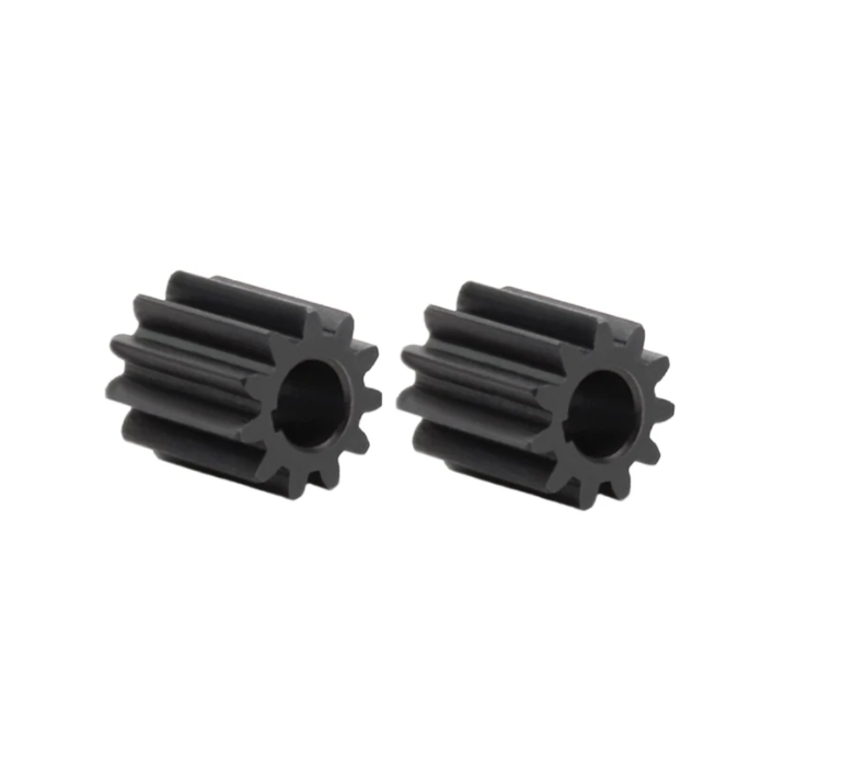
The failed component was a pinion gear whose root passed over a hexagonal steel bar. A bolt below the pinion gear clamped the assembly together. During assembly, tightening the bolt generated a tensile stress concentration at the root of the pinion gear. The fracture location was at the thinnest and most highly constrained section of the pinion gear. This location is consistent with the expected stress concentration in the pinion gear geometry, but the applied load was far below the design tightening torque. Therefore, the pinion gear should not have fractured if the material had possessed the specified quenched-and-tempered microstructure and adequate grain-boundary strength.
The pinion gear material, 20Cr13 steel, is a martensitic stainless steel with moderate carbon content and approximately 12 to 14 wt% Cr. It is commonly used for components requiring a combination of corrosion resistance, wear resistance, and strength after quenching and tempering. The carbon content controls hardness and strength, while Cr provides corrosion resistance and hardenability. Because 20Cr13 steel has high hardenability, it can form martensite even during air cooling. The heat treatment of the pinion gear therefore requires careful control of austenitizing temperature, holding time, cooling rate, and tempering temperature. If the pinion gear is overheated or overburned, the grain boundaries can become weak, and the pinion gear may fail at low loads despite acceptable bulk hardness.
I considered several possible causes for the pinion gear fracture: incorrect chemical composition, insufficient hardness, excessive hardness, machining damage, hydrogen embrittlement, stress corrosion cracking, improper tightening, and heat-treatment defects. The subsequent sections describe how I evaluated each possibility and why the evidence pointed to overheating and overburning as the dominant causes of pinion gear failure.
Inspection Strategy for the Pinion Gear
I designed the investigation to combine bulk-material checks with local microstructural and fracture-surface evidence. Bulk chemical composition can confirm whether the pinion gear matches 20Cr13 steel, but it cannot reveal grain-boundary damage. Hardness can reveal average strength level, but it cannot detect narrow zones of ferrite, Cr segregation, or incipient grain-boundary melting. Metallography and scanning electron microscopy are necessary to reveal the condition of the grain boundaries in the pinion gear. Elemental mapping is necessary to determine whether Cr redistributed during thermal exposure. Table 1 summarizes the inspection methods I used and the information each method provided.
| Method | Purpose | Information Obtained for the Pinion Gear |
|---|---|---|
| Macroscopic observation | Identify fracture location and general fracture appearance | Root fracture, porcelain-like gray surface, no obvious plastic deformation |
| Chemical composition analysis | Verify 20Cr13 steel specification | Composition conformed to the standard range for 20Cr13 steel |
| Hardness testing | Check acceptance requirement of 20 to 30 HRC | Measured 21 to 26 HRC, which passed the requirement but fluctuated |
| Metallographic examination | Observe microstructure and grain-boundary condition | Spheroidized pearlite, grain-boundary precipitates, overburning and overheating features |
| Scanning electron microscopy | Determine fracture mode and local morphology | Intergranular brittle fracture, sugar-like particles, some transgranular cleavage |
| Elemental mapping | Detect Cr segregation and remelting effects | Cr segregation in grain-boundary ferrite and remelted pits |
Chemical Composition of the Pinion Gear
I analyzed the chemical composition of the failed pinion gear using vacuum direct-reading optical emission spectrometry. The measured composition is compared with the specification for 20Cr13 steel in Table 2. The carbon, silicon, manganese, phosphorus, sulfur, chromium, and nickel contents were all within the required ranges. The measured Cr content of 12.12 wt% was slightly above the lower limit but still within the standard range. Therefore, I could not attribute the pinion gear fracture to a wrong grade or a major alloying error.
| Element | Measured Value (wt%) | Specified Range for 20Cr13 (wt%) |
|---|---|---|
| C | 0.23 | 0.16 to 0.25 |
| Si | 0.42 | ≤ 1.00 |
| Mn | 0.53 | ≤ 1.00 |
| P | 0.022 | ≤ 0.040 |
| S | 0.008 | ≤ 0.035 |
| Cr | 12.12 | 12.00 to 14.00 |
| Ni | 0.18 | ≤ 0.60 |
For a martensitic stainless steel such as 20Cr13, the carbon equivalent and chromium equivalent can provide a rough indication of hardenability and phase stability. I calculated the carbon equivalent using a common empirical expression:
$$ C_{eq} = C + \frac{Mn}{6} + \frac{Cr + Mo + V}{5} + \frac{Ni + Cu}{15} $$
Using the measured values and neglecting Mo, V, and Cu, the carbon equivalent was approximately:
$$ C_{eq} \approx 0.23 + \frac{0.53}{6} + \frac{12.12}{5} + \frac{0.18}{15} \approx 2.76 $$
This high value reflects the strong effect of Cr on hardenability. It also means that the pinion gear can transform to martensite over a wide range of cooling rates, including air cooling. Therefore, an improper heat treatment can easily produce a hard and brittle pinion gear if tempering is inadequate. Conversely, an improper high-temperature treatment can produce grain-boundary damage that hardness testing may not detect.
Hardness Response of the Pinion Gear
I tested the hardness of the pinion gear near the fracture location. The measured hardness values ranged from 21 to 26 HRC. Although all readings satisfied the drawing requirement of 20 to 30 HRC, the scatter was significant. The mean hardness and standard deviation were approximately:
$$ \bar{H} = \frac{1}{n}\sum_{i=1}^{n} H_i \approx 23.5\ \mathrm{HRC} $$
$$ s = \sqrt{\frac{1}{n-1}\sum_{i=1}^{n}(H_i – \bar{H})^2} \approx 1.8\ \mathrm{HRC} $$
The hardness range itself did not indicate an obvious nonconformance. However, hardness is a bulk property and is influenced by the volume fraction of hard phases, the local carbon content, and the indentation location. A pinion gear with weak grain boundaries, ferrite bands, or remelted pits can still exhibit an average hardness within the specification. Therefore, the hardness acceptance test was insufficient to guarantee the structural integrity of the pinion gear.
| Measurement | Value | Interpretation |
|---|---|---|
| Minimum hardness | 21 HRC | Within specification |
| Maximum hardness | 26 HRC | Within specification |
| Mean hardness | Approximately 23.5 HRC | Within specification |
| Standard deviation | Approximately 1.8 HRC | Noticeable scatter |
| Required range | 20 to 30 HRC | Passed |
Macroscopic Fracture Appearance of the Pinion Gear
The fractured pinion gear showed that the crack initiated at the root, which was the structurally weakest region. The fracture surface had a porcelain-like appearance, gray color, and no metallic luster. There was no obvious macroscopic crack origin, and I did not observe significant necking or plastic deformation. The fracture path appeared to follow the constraint direction imposed by the threaded hole and the clamping geometry. Based on the geometry, I concluded that the fracture initiated on the outer side of the hexagonal region of the pinion gear. This location is consistent with a tensile stress concentration when the bolt was tightened.
The absence of gross plastic deformation indicated that the pinion gear did not fail by ductile overload. The porcelain-like surface suggested a brittle fracture mode. Such an appearance is often associated with intergranular or cleavage fracture in high-hardness or grain-boundary-weakened steels. For the pinion gear, this appearance was the first indication that the fracture was not caused by simple mechanical overload of a sound material.
Metallographic Examination of the Pinion Gear
I prepared metallographic samples from the region near the fracture of the pinion gear. After polishing, I etched the samples with a ferric chloride hydrochloric acid aqueous solution and examined them under an optical microscope. The microstructure consisted primarily of a ferrite matrix with granular cementite, which is spheroidized pearlite. Along the grain boundaries, I observed large amounts of gray precipitates. Outside the pearlite regions, some grain boundaries contained black banded structures mixed with white blocky constituents. This microstructure was not the expected quenched-and-tempered sorbite for a 20Cr13 pinion gear.
To distinguish overheating from overburning, I further etched the metallographic sample in a 10 vol% sulfuric acid nitric acid solution for 30 s, rinsed it with water, wiped it with degreased cotton, and repeated this procedure three times. After light polishing, I examined the sample again under the optical microscope. The entire sample surface appeared gray and was densely covered with black spots. The black spots were corrosion pits. In the surrounding matrix, some grain boundaries appeared white and discontinuous, which is a characteristic of overburning. Other grain boundaries in the gray matrix appeared black, which is a characteristic of overheating. The pinion gear therefore contained both overheated and overburned regions.
| Microstructural Feature | Observed Condition in the Pinion Gear | Interpretation |
|---|---|---|
| Matrix | Ferrite with granular cementite | Spheroidized pearlite, not the expected tempered sorbite |
| Grain-boundary precipitates | Large gray precipitates | Ferrite precipitation associated with overheating |
| Banded grain-boundary regions | Black bands with white blocky constituents | Possible remelted zones and local phase transformation |
| Corrosion pits | Dense black spots after special etching | Overburning and grain-boundary remelting |
| White discontinuous grain boundaries | Local regions after etching | Overburning characteristic |
| Black grain boundaries | Gray matrix regions after etching | Overheating characteristic |
The presence of spheroidized pearlite was important. A properly quenched-and-tempered 20Cr13 pinion gear should contain tempered martensite or tempered sorbite, not spheroidized pearlite. Spheroidized pearlite can form during annealing or during tempering at an excessively high temperature. Because 20Cr13 steel has high hardenability, even air cooling after austenitizing can produce martensite. If the pinion gear had been properly quenched and tempered, it would not have exhibited a predominantly spheroidized pearlite matrix. The observed microstructure therefore indicated that the heat treatment of the pinion gear was not properly controlled.
Scanning Electron Microscopy of the Pinion Gear Fracture
I examined the fracture surface of the pinion gear using scanning electron microscopy. From the fracture initiation region to the final fracture region, the microscopic appearance was similar. The fracture surface consisted of sugar-like particles, which is typical of intergranular fracture. The grain facets were not smooth, and some transgranular cleavage was present between the intergranular regions. I did not observe fatigue striations, corrosion products, or dimples. These features confirmed that the pinion gear failed by brittle fracture rather than fatigue or ductile overload.
I also observed banded structures along the grain boundaries. These bands showed cleavage fracture characteristics. To identify the constituents, I examined the metallographic sample in the scanning electron microscope. The precipitates along the grain boundaries were δ ferrite, which is a hard and brittle phase and a characteristic of overheating. The black banded structures were pit-like defects that extended along the grain boundaries into the matrix. These pits were characteristic of grain-boundary melting and overburning. Inside the pits, I found white blocky and spherical particles. Elemental mapping showed that both the grain-boundary ferrite and the particles inside the pits had obvious Cr segregation. This indicated that the particles inside the pits were remelted products of precipitated ferrite.
| SEM Feature | Observation on the Pinion Gear | Meaning |
|---|---|---|
| Fracture mode | Sugar-like intergranular facets | Brittle intergranular fracture |
| Secondary mode | Local transgranular cleavage | Mixed brittle fracture |
| Fatigue evidence | None | Not a fatigue failure |
| Grain-boundary phase | δ ferrite | Overheating |
| Black bands | Pits extending along grain boundaries | Overburning and remelting |
| White particles | Spherical blocky particles in pits | Remelted ferrite with Cr segregation |
Elemental Segregation and Grain-Boundary Damage
I used elemental mapping to study the distribution of Cr and other elements in the pinion gear microstructure. The maps showed clear Cr segregation at the grain boundaries, especially in the δ ferrite and in the particles inside the remelted pits. This segregation is significant because Cr is a ferrite stabilizer and a carbide former. When the pinion gear is exposed to excessive temperature, Cr can diffuse toward grain boundaries and form Cr-rich regions. At the same time, the adjacent matrix can become depleted in Cr, reducing local corrosion resistance and altering phase stability. The grain-boundary regions can then transform to ferrite or even melt if the local composition and temperature reach the solidus or eutectic temperature.
The driving force for Cr segregation can be described qualitatively by a segregation equation:
$$ C_{gb} = C_0 \exp\left(-\frac{\Delta G_{seg}}{RT}\right) $$
where \(C_{gb}\) is the grain-boundary concentration, \(C_0\) is the bulk concentration, \(\Delta G_{seg}\) is the segregation free energy, \(R\) is the gas constant, and \(T\) is the absolute temperature. At high temperature, diffusion is faster, and segregation can become more extensive. The diffusion coefficient follows an Arrhenius relationship:
$$ D = D_0 \exp\left(-\frac{Q}{RT}\right) $$
where \(D_0\) is the pre-exponential factor and \(Q\) is the activation energy for diffusion. The combination of high temperature and sufficient time allowed Cr in the pinion gear to redistribute. The result was a grain-boundary region that was chemically different from the matrix and susceptible to melting, ferrite formation, and embrittlement.
Grain-boundary melting can be promoted by solute segregation because segregation lowers the local melting point. A simplified expression for the melting-point depression caused by a segregated element is:
$$ T_m = T_m^0 – \frac{R T_m^0}{\Delta H_f} \ln\left(\frac{1}{X_{Cr}}\right) $$
where \(T_m^0\) is the melting point of the pure matrix, \(\Delta H_f\) is the heat of fusion, and \(X_{Cr}\) is the local mole fraction of Cr. Although this expression is approximate, it illustrates why Cr-rich grain boundaries can melt below the bulk solidus temperature. When local melting occurs, the grain boundaries form liquid films. On cooling, these films solidify as remelted zones with altered composition and morphology. The original grain-boundary cohesion is destroyed, and the pinion gear becomes susceptible to intergranular fracture.
Thermal History Reconstruction for the Pinion Gear
The combination of overheated and overburned microstructures indicated that the pinion gear experienced a thermal excursion above the safe austenitizing range. Overheating usually occurs when the steel is held at too high a temperature for too long, causing grain growth and precipitation of ferrite along prior austenite grain boundaries. Overburning occurs at even higher temperatures, when grain boundaries begin to melt. In the pinion gear, the presence of δ ferrite along grain boundaries, Cr segregation, and remelted pits provided strong evidence for both conditions.
I reconstructed the likely thermal history of the pinion gear as follows. During heating, the pinion gear exceeded the recommended austenitizing temperature. Grain growth occurred, and Cr diffused toward grain boundaries. At the grain boundaries, the local Cr concentration increased and the local melting point decreased. When the temperature reached the local solidus, thin liquid films formed at the grain boundaries. On cooling, these films solidified as Cr-rich ferrite or as fine remelted particles. The grain-boundary regions became incoherent with the matrix, and their load-bearing capacity was greatly reduced. Later, during bolt tightening, the tensile stress at the pinion gear root caused intergranular crack initiation and propagation.
| Stage | Thermal or Mechanical Event | Microstructural Consequence in the Pinion Gear |
|---|---|---|
| 1 | Heating above the recommended temperature | Grain growth and increased diffusion rate |
| 2 | Extended holding at high temperature | Cr segregation toward grain boundaries |
| 3 | Local temperature exceeds grain-boundary solidus | Incipient melting and remelting at grain boundaries |
| 4 | Cooling after high-temperature exposure | δ ferrite precipitation and Cr-rich remelted particles |
| 5 | Subsequent heat treatment or tempering | Spheroidized pearlite instead of tempered sorbite |
| 6 | Bolt tightening during assembly | Intergranular fracture at the pinion gear root |
Mechanical and Fracture-Mechanics Considerations
The fracture of the pinion gear occurred during tightening, which imposed a combination of clamping force, friction, and bending at the root. The bolt torque can be related to the axial clamping force by:
$$ T = K F d $$
where \(T\) is the applied torque, \(K\) is the nut factor, \(F\) is the clamping force, and \(d\) is the nominal bolt diameter. Even before a torque wrench was used, manual tightening could generate a significant axial force. The pinion gear root experienced a local tensile stress concentration. For a simplified bending geometry, the nominal bending stress can be estimated by:
$$ \sigma_b = \frac{M c}{I} $$
where \(M\) is the bending moment, \(c\) is the distance from the neutral axis to the outer fiber, and \(I\) is the second moment of area. The stress concentration factor at the root is:
$$ K_t = \frac{\sigma_{max}}{\sigma_{nom}} $$
For a sound quenched-and-tempered pinion gear, the material should tolerate this stress without fracture. However, the grain boundaries in the failed pinion gear had lost cohesion. The effective fracture resistance of the grain boundaries was much lower than that of the matrix. The Griffith-type relationship for brittle fracture can be written as:
$$ \sigma_f = \sqrt{\frac{2E\gamma_s}{\pi a}} $$
where \(\sigma_f\) is the fracture stress, \(E\) is the elastic modulus, \(\gamma_s\) is the surface energy, and \(a\) is the flaw size. In the pinion gear, the grain-boundary films, ferrite precipitates, and remelted pits acted as pre-existing flaws and weak paths. The effective surface energy for intergranular fracture was lower than that for transgranular fracture, so the fracture stress was reduced. This explains why the pinion gear fractured at such a low applied load.
The Hall-Petch relationship also provides context for the role of grain size and grain-boundary strength:
$$ \sigma_y = \sigma_0 + k_y d^{-1/2} $$
where \(\sigma_y\) is the yield strength, \(\sigma_0\) is the friction stress, \(k_y\) is the strengthening coefficient, and \(d\) is the grain diameter. Overheating can coarsen the grains and reduce the grain-boundary area, but the more damaging effect in the pinion gear was the chemical and structural degradation of the grain boundaries themselves. A coarse grain structure with weak boundaries cannot provide the expected strength or toughness. The pinion gear therefore behaved as a brittle material despite a hardness reading that appeared acceptable.
Role of Ferrite and Cr Segregation in the Pinion Gear
The presence of δ ferrite along the grain boundaries was a critical factor in the pinion gear failure. δ ferrite is relatively soft compared with martensite or tempered sorbite, but it can be brittle under constraint, especially when it forms a continuous or semi-continuous network along prior austenite grain boundaries. In the pinion gear, the ferrite bands provided a path for intergranular crack propagation. The Cr segregation in these bands further altered their mechanical and chemical behavior. Because Cr is a ferrite stabilizer, local Cr enrichment can stabilize ferrite at temperatures where austenite would normally be stable. This can create a duplex or ferrite-containing microstructure that is not intended for a quenched-and-tempered pinion gear.
The Cr-depleted regions adjacent to the grain boundaries may also have lower hardenability and corrosion resistance. During cooling, these regions can transform to ferrite or to other soft phases instead of martensite. The resulting microstructure is heterogeneous. Hardness testing may average over the soft and hard regions, producing readings within specification. However, the local grain-boundary regions remain weak. When the pinion gear is loaded, cracks initiate at these weak boundaries and propagate along them. The fracture surface then exhibits the sugar-like intergranular morphology observed in the scanning electron microscope.
| Feature | Effect on the Pinion Gear | Consequence |
|---|---|---|
| δ ferrite at grain boundaries | Creates a brittle grain-boundary network | Intergranular crack path |
| Cr segregation | Stabilizes ferrite and lowers local melting point | Remelting and heterogeneous microstructure |
| Cr-depleted matrix | Reduces hardenability and corrosion resistance | Soft zones and reduced local integrity |
| Remelted pits | Acts as stress concentrators and flaws | Low-stress crack initiation |
| Spheroidized pearlite | Lower strength than tempered sorbite | Reduced load capacity of the pinion gear |
Why Hardness Testing Did Not Prevent the Pinion Gear Failure
Hardness testing is commonly used as a final acceptance check for heat-treated components. It is fast, relatively inexpensive, and can be performed on the pinion gear without complete destruction. However, hardness is not a direct measure of grain-boundary integrity. A pinion gear can have an acceptable average hardness while containing severe grain-boundary defects. In this failure, the hardness of the pinion gear was 21 to 26 HRC, which fell within the 20 to 30 HRC requirement. If only hardness had been considered, the pinion gear would have been accepted. The fracture then occurred at low load because the grain boundaries were already degraded.
Hardness testing also has limited sampling volume. The indentation samples a small volume of material, and the result depends on where the indentation is placed. If the pinion gear has banded or segregated microstructures, different indentations can produce different values. The observed hardness scatter of 21 to 26 HRC was a warning sign, but it was not outside the specification. A more appropriate acceptance approach for a safety-critical pinion gear would include microstructural evaluation, process parameter monitoring, and destructive sampling at a specified frequency.
| Acceptance Method | Ability to Detect Overheating | Ability to Detect Overburning | Limitation for the Pinion Gear |
|---|---|---|---|
| Hardness testing | Low | Very low | Average value can remain within specification |
| Metallography | High | High | Destructive and time-consuming |
| Scanning electron microscopy | High | High | Not suitable for full production inspection |
| Elemental mapping | Moderate to high | High | Specialized and slow |
| Process parameter control | High | High | Requires disciplined furnace monitoring |
Fracture Sequence of the Pinion Gear
Based on all evidence, I reconstructed the fracture sequence of the pinion gear as shown in Table 7. The sequence begins with a thermal defect in the raw material or heat treatment and ends with final fracture during assembly. The critical point is that the pinion gear was already weakened before it was installed. The bolt tightening only provided the final stress that triggered failure.
| Step | Event | Evidence |
|---|---|---|
| 1 | Raw material or heat treatment exposed to excessive temperature | Overheating and overburning features in the pinion gear |
| 2 | Cr segregation at grain boundaries | Elemental maps showing Cr enrichment in ferrite and pits |
| 3 | Local grain-boundary melting and remelting | Pits extending along grain boundaries |
| 4 | δ ferrite precipitation along grain boundaries | SEM and metallographic observation |
| 5 | Loss of grain-boundary cohesion | Intergranular brittle fracture |
| 6 | Hardness acceptance passes | 21 to 26 HRC, within 20 to 30 HRC |
| 7 | Bolt tightening generates tensile stress at the pinion gear root | Fracture at the root during fastening |
| 8 | Crack initiation and intergranular propagation | Sugar-like fracture surface |
| 9 | Final fracture of the pinion gear | Complete separation at the root |
Expected Versus Observed Microstructure of the Pinion Gear
For a properly manufactured 20Cr13 pinion gear, the quenched-and-tempered condition should produce a tempered martensitic or tempered sorbite microstructure. The hardness should be uniform within the specified range. Grain boundaries should be clean and free of continuous ferrite networks or remelted films. The observed microstructure in the failed pinion gear differed significantly from this expected condition. Table 8 compares the expected and observed conditions.
| Characteristic | Expected for a Properly Heat-Treated Pinion Gear | Observed in the Failed Pinion Gear |
|---|---|---|
| Matrix | Tempered martensite or tempered sorbite | Spheroidized pearlite |
| Grain boundary | Clean, coherent, and free of continuous ferrite | δ ferrite precipitates and remelted pits |
| Cr distribution | Relatively uniform | Cr segregation at grain boundaries and pits |
| Hardness uniformity | Uniform within specification | 21 to 26 HRC with noticeable scatter |
| Fracture mode | Ductile or mixed mode if overloaded | Brittle intergranular fracture |
| Service performance | Able to withstand assembly tightening | Fractured at low load before torque wrench use |
Root Causes of the Pinion Gear Fracture
The root cause of the pinion gear fracture was an improper thermal history that produced overheating and overburning. Overheating caused grain-boundary ferrite precipitation and Cr segregation. Overburning caused local grain-boundary melting, remelting, and pit formation. These defects reduced the grain-boundary cohesion and made the pinion gear susceptible to intergranular brittle fracture. The heat treatment also failed to produce the expected tempered sorbite microstructure; instead, the pinion gear contained spheroidized pearlite. This microstructure had lower strength than the intended quenched-and-tempered structure.
Contributing causes included the use of hardness testing as the primary acceptance criterion, the lack of microstructural verification, and insufficient process control during heat treatment. Because the hardness of the pinion gear was within the specification, the defective pinion gear was accepted and entered assembly. The bolt tightening then applied sufficient stress to initiate and propagate a crack along the weakened grain boundaries. The pinion gear fractured before the specified torque was applied, demonstrating that the material had lost a large fraction of its load-bearing capacity.
Preventive Actions for Future Pinion Gear Production
To prevent recurrence, I recommend a combination of material control, heat-treatment control, inspection improvements, and assembly improvements. The most important action is to prevent overheating and overburning in the first place. Once overburning occurs, it cannot be corrected by subsequent heat treatment. The only safe disposition for an overburned pinion gear is scrap. Table 9 summarizes the recommended actions and their expected effects.
| Action | Implementation | Expected Effect on the Pinion Gear |
|---|---|---|
| Scrap the affected lot | Do not rework or reheat-treat overburned pinion gears | Prevents installation of defective pinion gears |
| Control austenitizing temperature | Use calibrated thermocouples and furnace controllers | Prevents grain growth and incipient melting |
| Control holding time | Set maximum soak time for the pinion gear | Limits Cr diffusion and grain-boundary segregation |
| Control cooling rate | Verify quench or air-cooling practice | Avoids undesirable ferrite and pearlite formation |
| Control tempering temperature | Prevent excessive tempering that forms spheroidized pearlite | Maintains tempered sorbite and target hardness |
| Add microstructural acceptance | Perform periodic destructive metallography | Detects overheating and overburning before shipment |
| Use process parameter records | Trace furnace batch, temperature, and time | Enables rapid containment if a deviation occurs |
| Improve tightening procedure | Use a torque wrench and verify clamping force | Reduces accidental overload of the pinion gear root |
| Review root geometry | Increase fillet radius if possible | Lowers stress concentration in the pinion gear |
Additional Quantitative Considerations
The thermal stress generated during heating or cooling can be estimated by:
$$ \sigma_{th} = \frac{E \alpha \Delta T}{1-\nu} $$
where \(\sigma_{th}\) is the thermal stress, \(E\) is Young’s modulus, \(\alpha\) is the coefficient of thermal expansion, \(\Delta T\) is the temperature difference, and \(\nu\) is Poisson’s ratio. If the thermal stress exceeds the local grain-boundary strength, cracking can occur even without external loading. In the pinion gear, the grain boundaries were already weakened by remelting and ferrite precipitation. Therefore, the critical temperature difference for damage was lower than it would be for a sound material.
The martensite start temperature for low-alloy and stainless steels can be approximated by:
$$ M_s = 561 – 474C – 33Mn – 17Ni – 17Cr – 21Mo $$
Using the measured composition and neglecting Mo, the martensite start temperature is approximately:
$$ M_s \approx 561 – 474(0.23) – 33(0.53) – 17(0.18) – 17(12.12) \approx 230\ \mathrm{^\circ C} $$
This value indicates that the pinion gear can form martensite during cooling. If the cooling rate is sufficient, the matrix should transform to martensite, which can then be tempered to the desired hardness. The observed spheroidized pearlite suggests that the pinion gear either was not properly austenitized and quenched or was subjected to an annealing or high-temperature tempering treatment that produced spheroidization. In either case, the heat-treatment schedule was not appropriate for the pinion gear.
The hardness requirement of 20 to 30 HRC corresponds approximately to a tempered martensitic structure with moderate strength. If the pinion gear contains spheroidized pearlite instead of tempered martensite, the hardness may still fall within the same range, but the strength and toughness will differ. Spheroidized pearlite has soft ferrite and coarse cementite particles, which can lower the yield strength and fatigue resistance. The pinion gear may pass hardness acceptance but still have inferior mechanical performance.
Discussion of Fracture Surface Features
The fracture surface of the pinion gear showed a porcelain-like gray appearance with no metallic luster. This appearance is consistent with brittle fracture. In scanning electron microscopy, the surface consisted of sugar-like particles, which are characteristic of intergranular separation. The grain facets were not smooth, and some areas showed transgranular cleavage. No fatigue striations were present, so cyclic loading was not the cause of failure. No dimples were present, so ductile overload was not the dominant mechanism. The fracture mode was therefore brittle intergranular fracture, which matched the metallographic evidence of weak grain boundaries.
The presence of intergranular fracture is especially significant in a pinion gear. A sound quenched-and-tempered pinion gear should generally exhibit transgranular fracture under overload, with some ductility. Intergranular fracture indicates that the grain boundaries were the weakest link. In this pinion gear, the grain boundaries contained δ ferrite, Cr segregation, and remelted pits. These features provided both a weak path and a stress concentration. The crack could therefore initiate at a relatively low applied stress and propagate along the prior austenite grain boundaries.
Corrosion and Environmental Effects
Although the pinion gear is made of 20Cr13 stainless steel, the Cr segregation and Cr depletion associated with overheating can reduce local corrosion resistance. The Cr-rich ferrite and remelted regions may act as cathodic or anodic sites, depending on composition. The surrounding matrix may become more susceptible to corrosion. In the failed pinion gear, however, I did not find evidence that corrosion initiated the fracture. The fracture surface was clean and brittle, without significant corrosion products. The primary role of Cr segregation was microstructural and mechanical rather than corrosive. It stabilized ferrite, lowered the local melting point, and contributed to grain-boundary embrittlement.
If the pinion gear were exposed to a corrosive environment in service, the Cr-depleted zones could become preferential corrosion paths. This would further weaken the grain boundaries and increase the risk of stress corrosion cracking. For a pinion gear that must operate in a moist or chemically active environment, the combination of Cr segregation and tensile stress could be especially dangerous. Therefore, the microstructural defects found in this pinion gear would be unacceptable even if the immediate fracture had not occurred during assembly.
Comparison With Other Possible Failure Mechanisms
I considered and rejected several alternative causes. The chemical composition was within specification, so a wrong material grade was unlikely. The hardness was within the required range, so gross under-hardening or over-hardening was not the direct cause. There was no evidence of fatigue striations, so fatigue was not the initiating mechanism. There were no corrosion pits or corrosion products on the fracture surface, so corrosion was not the primary cause. The fracture occurred during manual tightening before a torque wrench was used, so gross mechanical overload was unlikely. The only mechanism consistent with all observations was grain-boundary weakening caused by overheating and overburning.
| Alternative Mechanism | Evidence For | Evidence Against | Assessment for the Pinion Gear |
|---|---|---|---|
| Wrong chemical composition | None | Composition met 20Cr13 specification | Rejected |
| Insufficient hardness | Hardness at lower end of range | Hardness within 20 to 30 HRC | Not the primary cause |
| Fatigue | None | No fatigue striations | Rejected |
| Corrosion | Cr segregation present | No corrosion products on fracture surface | Not the initiating cause |
| Mechanical overload | Fracture during tightening | Low load before torque wrench use | Trigger, not root cause |
| Overheating and overburning | Ferrite, Cr segregation, remelted pits, intergranular fracture | None | Primary cause |
Practical Implications for Pinion Gear Manufacturing
The failure of this pinion gear shows that hardness acceptance alone is not sufficient for a critical heat-treated component. A pinion gear can meet the hardness requirement while containing severe microstructural defects. For 20Cr13 steel, the heat-treatment window must be controlled carefully. The austenitizing temperature should be high enough to dissolve carbides and achieve the desired hardness after quenching, but not so high that grain growth, ferrite precipitation, or incipient melting occurs. The holding time should be long enough for thermal equalization but short enough to limit diffusion and segregation. The cooling rate should be sufficient to avoid undesirable ferrite or pearlite formation. The tempering temperature should be selected to produce tempered sorbite or tempered martensite with the required hardness and toughness.
For the pinion gear, the observed spheroidized pearlite indicates that the heat treatment either did not reach the proper austenitizing condition or was followed by an excessive tempering or annealing treatment. Spheroidized pearlite can have hardness above 20 HRC, especially if the cooling rate during annealing is relatively fast. Therefore, hardness alone cannot distinguish between a properly tempered pinion gear and a pinion gear with spheroidized pearlite. Metallographic examination is necessary to verify the phase constituents and grain-boundary condition. In addition, process parameter records should be maintained for each heat-treatment batch so that any deviation can be traced.
Recommended Disposition and Follow-Up
Because overburning cannot be reversed by reheat treatment, all pinion gears from the affected lot should be quarantined and evaluated. If overburning is confirmed in representative samples, the lot should be scrapped. Re-tempering or re-austenitizing will not restore grain-boundary cohesion because the remelted regions and Cr segregation have already altered the local chemistry and structure. The pinion gear that fractured should be retained as evidence. Additional samples should be taken from the same heat-treatment batch for metallographic examination and, if possible, mechanical testing. The furnace records should be reviewed to identify the temperature excursion or process deviation that caused the overheating and overburning.
I also recommend that the assembly process be reviewed. Although the tightening operation triggered the fracture, the root cause was the defective material. Nevertheless, improvements in tightening control can reduce the risk of overload in sound pinion gears. A calibrated torque wrench should be used, and the clamping force should be verified. The root geometry of the pinion gear should be reviewed to ensure that the stress concentration is minimized. If the design allows, a larger fillet radius or a smoother transition at the root can reduce the local stress.
Final Conclusions
The pinion gear fractured during fastening because its grain boundaries had been severely weakened by overheating and overburning. The raw material or heat-treatment process exposed the pinion gear to an excessive temperature. This caused Cr segregation at grain boundaries, local melting and remelting, and precipitation of δ ferrite. The grain-boundary regions lost cohesion and became brittle. The matrix also failed to develop the expected tempered sorbite structure and instead contained spheroidized pearlite. Hardness testing did not detect these defects because the average hardness remained within the specified range of 20 to 30 HRC.
The fracture surface showed brittle intergranular features with sugar-like particles, confirming that the crack propagated along the weakened grain boundaries. No fatigue striations, corrosion products, or ductile dimples were observed. The fracture initiation site was at the pinion gear root, where bolt tightening produced a tensile stress concentration. The applied load was low, but the grain-boundary strength of the pinion gear was even lower. Therefore, the pinion gear fractured before the specified tightening torque was reached.
Overburning cannot be corrected by subsequent heat treatment. The affected pinion gears should be scrapped. Future production should rely on process parameter control, periodic microstructural examination, and proper heat-treatment specifications rather than hardness testing alone. By controlling austenitizing temperature, holding time, cooling rate, and tempering temperature, the manufacturer can ensure that the pinion gear develops the intended tempered microstructure and maintains adequate grain-boundary cohesion. These actions will prevent similar pinion gear fractures and improve the reliability of the assembly.