
I designed a planetary pinion gear driven disturbance-assisted high-speed precision seed metering device to overcome the leakage, blockage, and poor seed-filling stability that occur in mechanical maize meters at high forward speeds. The core idea of my design is to use a planetary pinion gear train to generate a reverse and differential motion between an agitation ring and a seed plate. This motion creates a time-varying disturbance field above the cells, activates the seed population in the filling zone, and promotes single-seed filling. In this article, I present the structural design, kinematic modeling, force analysis, parameter optimization, bench experiments, and field validation of the proposed device. I use the term pinion gear repeatedly because the pinion gear is the central transmission element that enables the reverse differential agitation. The planetary pinion gear arrangement is compact, robust, and suitable for mechanical precision maize seeding.
Maize is a major food and feed crop, and precision planting directly affects yield, seed consumption, and crop uniformity. Mechanical seed meters are simple, reliable, and low in cost, but at high operating speeds the filling time becomes very short. Seeds tend to arch, bridge, and stagnate in the filling zone, which reduces the qualified rate and increases both multiple and leakage rates. Pneumatic meters can improve high-speed filling, but they require complex air systems, higher power, and have limited adaptability to seed shape and size. Therefore, I focused on a mechanical solution that uses a planetary pinion gear drive to actively disturb the seed population and enhance filling without external air assistance.
The proposed meter consists of a rear housing, a planetary carrier, an input shaft, planetary pinion gear shafts, a sun gear, planetary pinion gears, an internal ring gear, a seed guide wheel, a seed transfer partition, a seed plate, an agitation ring, and a seed inlet cover. The agitation ring is mounted on four uniformly distributed planetary pinion gear shafts. It rotates in the opposite direction and at a different speed relative to the seed plate. This relative motion creates a continuously changing interference flow field in the filling zone, breaks up seed accumulation, and drives seeds into the cells. The combination of the agitation ring and the seed plate cells forms the disturbance-assisted filling zone, which is the key functional region of my design.
The working process of the meter can be divided into five stages: filling, cleaning, transferring, guiding, and dropping. During operation, a motor or ground wheel drives the seed plate and the planetary pinion gear train. The agitation ring rotates with the planetary pinion gear train and disturbs the seed population in the filling zone. Seeds are pushed into the cells. When the seed-taking unit rotates to a certain angle, excess seeds fall back under gravity, leaving only one seed per cell. The single seed continues to rotate with the seed plate and is transferred through an opening in the partition into a seed guide groove on the seed guide wheel. The seed guide wheel rotates synchronously with the seed plate and carries the seed to the lower right discharge port. The seed then falls into a seed tube under gravity and initial velocity, completing the single-seed precision metering process.
I selected maize seed shape and size as the basis for structural design. I classified seeds into dent, cone-spherical, and spherical types. The number ratio of these three types was approximately 6:3:1. I randomly selected 100 seeds of each type and used a three-dimensional scanner to obtain point cloud data. I established a three-dimensional coordinate system with the seed centroid as the origin, where the x, y, and z axes corresponded to seed length, width, and thickness. The measured size ranges are summarized in Table 1. These data were used to design the cell geometry and the seed plate parameters.
| Seed type | Parameter | Range (mm) |
|---|---|---|
| Dent | Length | 10.68–13.39 |
| Dent | Width | 7.63–10.11 |
| Dent | Thickness | 3.91–6.17 |
| Cone-spherical | Length | 11.05–13.92 |
| Cone-spherical | Width | 6.02–9.55 |
| Cone-spherical | Thickness | 4.25–8.36 |
| Spherical | Length | 7.72–9.88 |
| Spherical | Width | 7.61–10.18 |
| Spherical | Thickness | 7.41–9.28 |
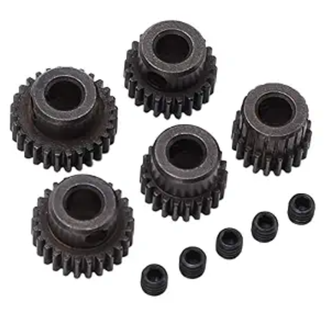
The transmission system of my meter uses an NGW planetary pinion gear train. The internal ring gear is fixed to the housing. The seed plate and the planetary carrier are integrated, so the seed plate itself acts as the planetary carrier and the power input member. The sun gear acts only as an idler and participates in meshing transmission. The planetary pinion gears are uniformly mounted on planetary pinion gear shafts. Each planetary pinion gear meshes externally with the sun gear and internally with the internal ring gear. This forms a compact coaxial double-meshing planetary pinion gear transmission system. The pinion gear motion is the source of the reverse differential agitation.
Power is input to the planetary carrier through the drive shaft. Because the internal ring gear is fixed, the carrier drives each planetary pinion gear to perform a compound motion consisting of revolution and self-rotation. The agitation ring assembly is mounted on the planetary pinion gear shaft. The compound motion of the planetary pinion gear creates a time-varying interference field in the filling zone. This establishes a coaxial differential relative motion between the seed plate and the agitation ring. Through the connection of the output members and the transmission path, the agitation ring moves in the opposite direction and at a different speed relative to the seed plate. This provides the kinematic foundation for disturbance-assisted filling.
To establish the speed constraint of the transmission system, I used a relative motion analysis method with the planetary carrier as the reference frame. For an NGW planetary pinion gear train, the sun gear and the planetary pinion gear form an external meshing pair, while the internal ring gear and the planetary pinion gear form an internal meshing pair. In the carrier coordinate system, the Willian speed relation is satisfied:
$$ n_s – n_c = – \frac{Z_r}{Z_s} (n_r – n_c) $$
where \(n_s\) is the sun gear speed, \(n_r\) is the internal ring gear speed, \(n_c\) is the planetary carrier or seed plate speed, \(Z_s\) is the number of sun gear teeth, and \(Z_r\) is the number of internal ring gear teeth. In my working condition, the internal ring gear is fixed, so \(n_r = 0\). The carrier provides the input speed \(n_c\). Substituting \(n_r = 0\) into the equation and rearranging gives the transmission ratio:
$$ i = \frac{n_s}{n_c} = 1 + \frac{Z_r}{Z_s} $$
The self-rotation of the planetary pinion gear is determined jointly by the relative speed constraints of the internal and external meshing pairs in the carrier system. Taking the internal and external meshing pairs as objects, the speed compatibility relation is:
$$ (n_s – n_c) Z_s + n_p Z_p = 0 $$
$$ (n_r – n_c) Z_r – n_p Z_p = 0 $$
where \(Z_p\) is the number of planetary pinion gear teeth and \(n_p\) is the planetary pinion gear or agitation ring speed. Combining these relations yields:
$$ n_p = – \frac{Z_r}{Z_p} n_c $$
This equation shows that the self-rotation direction of the planetary pinion gear relative to the carrier is opposite to that of the carrier. Its speed is proportional to the tooth number ratio and the input speed \(n_c\). Combining the above equations, I found that \(n_s\) and \(n_c\) are in the same direction but at different speeds, while \(n_p\) and \(n_c\) are in opposite directions and at different speeds. Therefore, when a reverse and adjustable disturbance motion is required in the circumferential direction of the seed plate, it can be achieved by adjusting the tooth number combination or the final speed ratio. Because the overall size of the meter is fixed, I adjusted the number of disturbance rods on the agitation ring to regulate the disturbance amplitude.
In the design of the NGW planetary pinion gear train, the selection of gear parameters determines not only the kinematic characteristics and speed ratio but also the meshing accuracy, load distribution, and assembly manufacturability. Based on the low-speed, light-load, and compact working characteristics of a mechanical seed meter, I selected 40CrMo as the gear material. The module \(m\) ranged from 1 to 3 mm. The accuracy grade was set to grade 9 according to ISO 1328. Due to the geometric constraints of the whole machine, the pitch circle diameter of the internal ring gear \(d_r\) was fixed at 205 mm. To optimize the coverage of the disturbance field and ensure filling uniformity, the number of planetary pinion gears \(C_s\) was set to 4. To ensure manufacturability, assembly, and running stability, the tooth number design had to satisfy four geometric and assembly constraints.
The first constraint is the tooth profile measurability condition. The addendum circle radius of the internal ring gear must not be smaller than the base circle radius. Otherwise, the tooth groove width changes non-monotonically, the tooth profile measuring bar cannot enter the groove, and interference occurs between the addendum and dedendum. From the gear geometry:
$$ d_a \ge d_b $$
$$ d_a = m Z_r + 2 m h_a^* $$
$$ d_b = m Z_r \cos \alpha $$
where \(d_a\) is the addendum circle radius of the internal ring gear, \(d_b\) is the base circle radius, \(h_a^*\) is the addendum height coefficient, and \(\alpha\) is the pressure angle. Combining these gives:
$$ 1 + \frac{2 h_a^*}{Z_r} \ge \cos \alpha $$
The second constraint is that the center distances of the internal and external meshing pairs must be identical. This ensures that the planetary pinion gear shaft trajectory is a concentric circle and avoids meshing interference. Therefore:
$$ Z_r = Z_s + 2 Z_p $$
The third constraint is the assembly closure condition for multiple planetary pinion gears. To allow all planetary pinion gears to mesh correctly with both the sun gear and the internal ring gear and to be uniformly distributed, the following condition must be satisfied:
$$ \frac{Z_r – Z_s}{C_s} = k, \quad k \in \mathbb{Z} $$
The fourth constraint is the geometric clearance between adjacent planetary pinion gear addendum circles. A sufficient gap must be maintained to prevent collision or addendum interference during operation. The geometric relation is:
$$ h = R_p \sin \theta_p – 4 d_a \ge h_{\min} $$
where \(h\) is the straight-line clearance between adjacent planetary pinion gear addendums, \(R_p\) is the planetary center orbit radius, \(\theta_p\) is the angle between adjacent planetary centers, and \(h_{\min}\) is the minimum clearance. The parameters \(R_p\), \(\theta_p\), and \(d_a\) are given by:
$$ R_p = a_s $$
$$ \theta_p = \frac{2 \pi}{C_s} $$
$$ d_a = 4 m (Z_p + 2 h_a^*) $$
where \(a_s\) is the center distance between the sun gear and the planetary pinion gear pitch circles. Substituting these into the clearance equation gives:
$$ m (Z_s + Z_p) \sin \frac{\pi}{C_s} \ge m (Z_p + 2 h_a^*) + h_{\min} $$
After satisfying these four constraints, I performed systematic tooth number calculation and parameter optimization. The main structural parameters of the NGW planetary pinion gear train are listed in Table 2. The pinion gear tooth numbers, module, pressure angle, and modification coefficients were selected to ensure compactness, smooth meshing, and sufficient load capacity.
| Category | Parameter | Sun gear | Planetary pinion gear | Internal ring gear |
|---|---|---|---|---|
| Tooth number | \(Z\) | 18 | 32 | 82 |
| Module | \(m\) (mm) | 2.5 | 2.5 | 2.5 |
| Pressure angle | \(\alpha\) (°) | 20 | 20 | 20 |
| Helix angle | \(\beta\) (°) | 0 | 0 | 0 |
| Tooth width | \(b\) (mm) | 15 | 15 | 15 |
| Addendum coefficient | \(h_a^*\) | 1 | 1 | 1.109 |
| Dedendum coefficient | \(h_f^*\) | 1.25 | 1.25 | 1.104 |
| Bottom clearance coefficient | \(c_n^*\) | 0.25 | 0.25 | -0.005 |
| Modification coefficient | \(x\) | 0.415 | 0.295 | 1.157 |
| Pitch diameter | \(d\) (mm) | 45 | 80 | 205 |
| Base diameter | \(d_b\) (mm) | 42.29 | 75.18 | 192.63 |
| Working pitch diameter | \(d’\) (mm) | 46.29 | 82.29 | 210.87 |
| Addendum diameter | \(d_a\) (mm) | 52.08 | 86.48 | 205.24 |
| Dedendum diameter | \(d_f\) (mm) | 40.83 | 75.23 | 216.30 |
| Span tooth number | \(k_0\) | 3 | 5 | 11 |
| Common normal length | \(w_k\) (mm) | 19.79 | 34.84 | 82.34 |
| Measuring pin diameter | \(d_m\) (mm) | 5.8 | 5.5 | 5.3 |
The agitation ring is the final executive component of the planetary pinion gear drive system. Its function is to convert the revolution and self-rotation of the planetary pinion gear into periodic disturbance of the seed population. This creates a reverse, differential, and non-steady activation and filling effect in the coaxial space of the seed plate. The design goal is to construct a uniformly distributed dynamic disturbance field within the limited geometric space. This keeps the particle population in the filling zone activated, reduces static friction locking and arching, and improves seed flowability and cell filling uniformity.
To balance disturbance intensity and reliability, I selected thermoplastic polyurethane with 70D hardness for the disturbance rods. Its elongation at break is greater than 300%, and its tensile strength is 35 MPa. The agitation ring body is a circular ring structure with a diameter \(d_r\) of 25 mm and a ring thickness \(b_r\) of 10 mm. Disturbance rod groups are uniformly distributed along the circumference. The geometry of the disturbance rod directly determines the spatial characteristics of the disturbance flow field. I used a spiral disturbance rod with one spiral turn. Its pitch is equal to the disturbance length \(L_r\), and the helical line diameter corresponds to the disturbance rod diameter \(d_t\). The spiral disturbance rod has a gradual incidence angle, which enhances disturbance while avoiding severe seed jamming, making the disturbance smoother.
The reverse differential motion between the agitation ring and the seed plate forms a periodic shear field at the cell opening. Taking the end of the disturbance rod as the analysis object, the tangential relative speed between the disturbance rod and the seed plate is:
$$ v_t = \frac{2 \pi}{60} | n_c – n_p | L_r $$
where \(v_t\) is the tangential relative speed between the disturbance rod and the seed plate. This relative speed determines the shear intensity in the disturbance zone and thus affects the fluidization degree of the particles. A higher relative speed can increase the local kinetic energy of the seed population, but if it is too high, it may cause seed rebound and cell opening disturbance.
The swept volume per unit time of the disturbance rod is:
$$ V_e = N_r \pi d_t L_r v_t $$
where \(V_e\) is the swept volume, \(N_r\) is the number of disturbance rods, and \(d_t\) is the disturbance rod diameter. This equation shows that \(V_e\) is proportional to both \(L_r\) and \(d_t\). However, their roles in filling promotion are different. The length \(L_r\) directly determines the disturbance coverage and energy penetration depth, and it is the main geometric factor affecting filling efficiency. The diameter \(d_t\) mainly affects the particle contact force and local shear rate, while its influence on the overall disturbance field distribution is relatively weak.
The disturbance length \(L_r\) must simultaneously satisfy coverage, non-interference, and geometric constraints. From the geometric analysis, the design must satisfy:
$$ L_r < \frac{d_z – (d_s + d_p + d_r)}{2} $$
$$ L_r < \frac{\sqrt{2} (d_s + d_p)}{4} $$
$$ L_r > d_x $$
where \(d_z\) is the seed plate diameter, \(d_s\) is the sun gear pitch diameter, \(d_p\) is the planetary pinion gear pitch diameter, and \(d_x\) is the diameter of the connection point between the cell and the seed plate. Substituting the parameters gives a reasonable effective disturbance length \(L_r\) range of 20–32.5 mm. This interval satisfies the assembly requirements and ensures effective disturbance.
The disturbance rod diameter is limited by the space between the seed plate and the housing. If the diameter is too large, the planetary pinion gear shaft may interfere with the seed inlet cover or the cells, resulting in an excessively thick agitation ring and seed jamming between the agitation ring and the seed plate. Considering the average maize seed size, I selected \(d_t = 6\) mm. The agitation ring is fixed coaxially with the planetary pinion gear through a flat key and rotates with the planetary pinion gear. Because the planetary pinion gear performs compound motion in the NGW planetary pinion gear train, its self-rotation direction is opposite to that of the seed plate, which acts as the planetary carrier, and its speed is different. Therefore, the agitation ring moves in the opposite direction and at a different speed relative to the seed plate. This differential relationship causes the end of the disturbance rod to periodically sweep over the cell openings.
When the disturbance rod sweeps reversely across the cell opening area, its tangential component generates shear force and disturbance force. This continuously disturbs the seed population above the cell opening, causing seeds to roll, slide, and redistribute. This breaks the static particle structure and enhances particle flow. The process can be regarded as applying a time-varying filling-promoting disturbance field above the cells. It effectively reduces the particle packing density and contact stress at the cell opening, making it easier for seeds to enter the cells and achieving efficient filling.
The disturbance frequency of the agitation ring is:
$$ f_d = \frac{N_r | n_p – n_c |}{60} $$
Substituting the speed ratio between the seed plate and the agitation ring gives:
$$ f_d = \frac{N_r n_c (Z_r – Z_p)}{60 Z_p} $$
This shows that the disturbance frequency is proportional to the number of disturbance rods and the seed plate speed. The planetary pinion gear speed and the seed plate speed jointly determine the relative motion and the resulting disturbance frequency.
The rotation of the agitation ring creates periodic load disturbances in the filling zone, causing the contact force between seeds to change dynamically. The instantaneous contact force can be expressed as:
$$ F_i = F_0 + \Delta F \sin (\omega_p t) $$
where \(F_i\) is the instantaneous contact force between seeds, \(F_0\) is the average static contact force, \(\Delta F\) is the disturbance amplitude, \(\omega_p\) is the disturbance angular frequency, and \(t\) is the disturbance time. This periodic load fluctuation continuously breaks the static friction network of seeds above the cell opening, keeping the seed system in a fluidized state and improving filling capacity and uniformity.
To further reveal the filling promotion mechanism of the agitation ring, I established a force model for a single seed in the filling zone. When the disturbance rod rotates counterclockwise, its end applies a resultant force \(F_r\) to the seed. This resultant force can be decomposed into a normal component \(F_t\) and a tangential component \(F_n\). The normal component is perpendicular to the contact surface and mainly produces extrusion and impact, which breaks static friction locking and arch structures between seeds. The tangential component acts along the movement direction of the disturbance rod and drives the seed to roll and slide into the cell. The seed is also subjected to support force \(F_s\), friction force \(f\), centrifugal force \(F_c\), and gravity \(G\). According to static equilibrium, the force equations in the tangential and normal directions are:
$$ F_n + G \sin \gamma_g = F_s \cos \gamma_s + F_c \cos \gamma_c + f $$
$$ F_t + F_s \sin \gamma_s = G \cos \gamma_g + F_c \sin \gamma_c $$
where \(\gamma_g\) is the angle between gravity and the normal direction, \(\gamma_s\) is the angle between the support force and the normal direction, and \(\gamma_c\) is the angle between the centrifugal force and the normal direction. After decomposing the resultant force and substituting, I obtained:
$$ F_r \sin \theta = F_s (\cos \gamma_s + \mu) \cos \gamma_s + m_0 \omega_s^2 r \cos \gamma_c – m_0 g \sin \gamma_g $$
$$ F_r \cos \theta = m_0 g \cos \gamma_g + m_0 \omega_s^2 r \sin \gamma_c – F_s \sin \gamma_s $$
where \(\theta\) is the resultant force direction angle, \(\mu\) is the friction coefficient, \(m_0\) is the seed mass, \(g\) is gravitational acceleration, \(\omega_s\) is the disturbance rod angular speed, and \(r\) is the seed rotation radius, that is, the vertical distance from the centroid to the disturbance rod rotation axis. The total force and the resultant force direction angle are:
$$ F_r = \sqrt{ [F_s (\cos \gamma_s + \mu) + m_0 \omega_s^2 r \cos \gamma_c – m_0 g \sin \gamma_g]^2 + [m_0 g \cos \gamma_g + m_0 \omega_s^2 r \sin \gamma_c – F_s \sin \gamma_s]^2 } $$
$$ \theta = \arctan \frac{F_s (\cos \gamma_s + \mu) + m_0 \omega_s^2 r \cos \gamma_c – m_0 g \sin \gamma_g}{m_0 g \cos \gamma_g + m_0 \omega_s^2 r \sin \gamma_c – F_s \sin \gamma_s} $$
These equations show that the resultant force of the disturbance rod on the seed is jointly determined by the disturbance angular speed, gravity component, centrifugal force, and support force from neighboring seeds. The angle \(\theta\) determines the nature of the filling promotion. When \(\theta\) is in a suitable range, the normal component can effectively break the static structure without causing excessive impact, while the tangential component can fully excite seed rolling and sliding. Together, they achieve efficient filling promotion of the population above the cell opening.
The seed plate in my design also serves as the planetary carrier. It is coaxially connected with the planetary pinion gear drive system and participates directly in seed distribution. The seed plate diameter determines the number and distribution of seed-taking units, and it is a key structural parameter affecting metering performance. To analyze the influence of the seed plate diameter \(d_z\) on the filling time \(t\), the geometric relation is:
$$ v_c t = l $$
$$ v_c = \frac{n_c \pi d_z}{60} $$
$$ l = \alpha_f r_c $$
where \(v_c\) is the linear speed of the seed plate, \(l\) is the arc length of the filling zone, \(\alpha_f\) is the filling zone angle in radians, and \(r_c\) is the radius at the cell center. Rearranging gives:
$$ t = \frac{60 \alpha_f r_c}{n_c \pi d_z} $$
This equation shows that the filling time \(t\) is proportional to the filling zone angle \(\alpha_f\) and inversely proportional to the seed plate diameter \(d_z\) and the seed plate speed \(n_c\). In other words, at a constant seed plate speed, increasing the diameter significantly extends the filling arc length, thereby increasing the filling time and improving filling sufficiency and cleaning reliability. A larger seed plate diameter also allows more seed-taking units to be arranged, which can reduce the working speed while maintaining the seeding rate and improve the smoothness of operation. Therefore, when the structural size and installation space permit, a larger seed plate diameter should be preferred to achieve the best balance between filling performance and metering accuracy.
In my design, the seed plate ring diameter \(d_z\) is 225 mm, and the thickness \(b_z\) is 3 mm. Four planetary pinion gear shaft holes are uniformly distributed around the circumference, each with a diameter \(d_h\) of 17 mm. A seed guide groove with a depth of 0.3 mm is arranged between adjacent seed-taking units to guide seeds efficiently into the units. The number of seed-taking units is:
$$ N_k = \frac{2 \pi r_c}{w_c} $$
where \(N_k\) is the number of seed-taking units and \(w_c\) is the spacing between seed-taking units. The radius at the cell center \(r_c\) is 105 mm. The spacing \(w_c\) must be greater than 1.5 times the maximum seed length; otherwise, filling is hindered. According to the seed size statistics, \(w_c\) should be greater than 22.4 mm, so I selected \(w_c = 24\) mm. Substituting this into the equation gives \(N_k = 27.49\), which I rounded to 27 seed-taking units. The relationship between the seed plate speed and the working speed is:
$$ n_c = \frac{2500 v_m}{3 N_k z} $$
where \(v_m\) is the working speed in km/h and \(z\) is the planting spacing in mm. With \(z = 25\) mm, the seed plate speed range under high-speed conditions from 8 to 20 km/h is 20–50 r/min. This speed range is compatible with the planetary pinion gear drive and the agitation ring.
The cell structure directly determines the filling and cleaning performance of the meter. After the cleaning stage, each cell must retain only one seed. Therefore, the cell parameters must be designed according to seed shape, size, and filling posture. The basic dimensions of the cell include the inlet width \(W_1\), internal width \(W_2\), wall height \(H_1\), depth \(H_2\), length \(L_1\), bottom inclination angle \(\gamma_1\), and entry angle \(\gamma_2\). The parameter values must be determined according to effective filling conditions.
The effective filling postures include a single seed filling the cell laterally, a single seed filling the cell longitudinally, two seeds both filling laterally, two seeds both filling longitudinally, one lateral seed and one longitudinal seed filling laterally, and one lateral seed and one longitudinal seed filling longitudinally. From these postures, the cell parameter ranges can be derived as:
$$ 0 \le H_1 \le t_0 $$
$$ 0 \le H_2 \le t_0 + w_0 $$
$$ 0 \le W_1 \le (t_0 + w_0) \cos \gamma_1 $$
$$ 0 \le W_2 \le t_0 $$
$$ 0 \le L_1 \le l_0 $$
where \(l_0\) is the maximum maize seed length, \(w_0\) is the maximum maize seed width, and \(t_0\) is the maximum maize seed thickness. The bottom inclination angle \(\gamma_1\) directly affects the opening shape of the filling inlet and thus determines the seed filling posture. If \(\gamma_1\) is too large, the seed posture does not match the cell; if it is too small, multiple seeds may refill. The entry angle \(\gamma_2\) determines the constraint force on the seed after filling. If \(\gamma_2\) is too large, cleaning becomes difficult; if it is too small, qualified seeds may be mistakenly cleaned. Based on previous studies, seed size ranges, and the derived equations, I optimized the key parameters of the seed-taking unit. The final values are listed in Table 3.
| Parameter | \(W_1\) (mm) | \(W_2\) (mm) | \(H_1\) (mm) | \(H_2\) (mm) | \(L_1\) (mm) | \(\gamma_1\) (°) | \(\gamma_2\) (°) |
|---|---|---|---|---|---|---|---|
| Value | 12 | 5.5 | 5 | 13 | 8 | 20 | 22 |
I conducted bench experiments to evaluate the performance of the proposed planetary pinion gear driven seed meter. The experiments were carried out in an agricultural equipment engineering center. I used ungraded Zhengdan 958 maize seeds. The gears were precision ground, the agitation ring was 3D printed from TPU, and the housing was machined from aluminum alloy. I built a test bench with a data acquisition system. The drive motor speed range was 0–50 r/min, and it drove the meter through a chain, sprocket, and transmission shaft. The conveying device included a PVC conveyor belt and a 60 W permanent magnet motor with a cast aluminum base. Its linear speed could be adjusted steplessly from 0 to 16 km/h to simulate different forward speeds. The data acquisition system included a high-speed camera and motion analysis software. The high-speed camera was placed horizontally with respect to the conveyor belt surface. The vertical distance between the lens center and the belt surface was about 15 cm. The field of view was adjusted so that the right edge was tangent to the outer edge of the seed tube outlet. The resolution was 720 pixels, and the sampling frame rate was 480 f/s. I collected more than 250 seeds per run and used the middle stable segment of 250 seeds for analysis. I imported the video into the motion analysis software, calibrated the pixel-to-physical scale, and obtained accurate seed spacing data.
I selected the disturbance length, the number of disturbance rods, and the working speed as experimental factors. The evaluation indicators were the qualified rate \(A\), the multiple rate \(D\), and the leakage rate \(M\), following the national standard for single-seed precision seeders. The maize planting spacing was 25 cm. I used the spacing of 250 seeds discharged under stable operation as the test sample. Each group was repeated three times, and the average was used.
To determine reasonable factor ranges, I first conducted single-factor experiments. With the number of disturbance rods fixed at 3 and the working speed at 12 km/h, I tested disturbance lengths of 26, 28, 30, 32, and 34 mm. With the disturbance length fixed at 30 mm and the working speed at 12 km/h, I tested disturbance rod numbers of 1, 2, 3, 4, 5, and 6. With the disturbance length fixed at 30 mm and the number of disturbance rods fixed at 3, I tested working speeds of 8, 10, 12, 14, and 16 km/h. The single-factor results showed the following trends. When the disturbance length increased from 26 to 30 mm, the qualified rate increased significantly, and the leakage and multiple rates decreased. When the disturbance length continued to increase to 34 mm, the qualified rate decreased, and multiple and leakage phenomena intensified. A short disturbance length caused insufficient disturbance, leading to incomplete filling and leakage. An excessively long disturbance length shifted the disturbance zone away from the cell opening, disturbed the seed motion trajectory, and caused multiple and leakage rates. The disturbance length range of 28–32 mm gave better metering performance. When the number of disturbance rods increased from 1 to 4, the qualified rate continued to increase and the leakage rate decreased. This was because the disturbance range expanded and uniformity improved, enhancing seed flowability and filling. When the number increased to 5, the qualified rate dropped sharply, and the leakage rate increased. The multiple rate also increased. This was caused by excessive disturbance, which compressed the seed flow space and increased ineffective collisions. When the number was 6, the leakage rate increased further, indicating that excessive disturbance aggravated instability. To ensure high performance and stability at high speed, I selected the disturbance rod number range of 2–4. The qualified rate first increased and then decreased with increasing speed, reaching a maximum at 12 km/h, where the multiple rate was also the lowest. The leakage rate was lowest at 8 km/h, increased at 12 km/h, and reached its highest at 16 km/h. At 8 km/h, the filling time was sufficient, so leakage was low, but local multiple filling occurred due to insufficient seed flow. At 10–12 km/h, moderate centrifugal force and disturbance optimized the seed fluidization state, giving the highest qualified rate and the lowest multiple rate, although the shortened filling time slightly increased leakage risk. When the speed exceeded 14 km/h, the excessively short filling time and large centrifugal force disturbed the seed motion trajectory, destroyed population stability, and simultaneously increased multiple and leakage rates, significantly reducing the qualified rate. To achieve the best balance between high qualified rate and low multiple rate, I selected the working speed range of 10–14 km/h.
Based on the single-factor results, I used the Box-Behnken design method with disturbance length, number of disturbance rods, and working speed as factors. The factor coding is shown in Table 4. I generated 17 experimental runs using Design-Expert software and completed the bench tests. The qualified rate \(Y_1\), multiple rate \(Y_2\), and leakage rate \(Y_3\) are listed in Table 5. The factors \(X_1\), \(X_2\), and \(X_3\) are the coded values of disturbance length, number of disturbance rods, and working speed, respectively.
| Coded level | \(X_1\): disturbance length (mm) | \(X_2\): number of disturbance rods | \(X_3\): working speed (km/h) |
|---|---|---|---|
| -1 | 28 | 2 | 10 |
| 0 | 30 | 3 | 12 |
| 1 | 32 | 4 | 14 |
| Run | \(X_1\) | \(X_2\) | \(X_3\) | \(Y_1\) (%) | \(Y_2\) (%) | \(Y_3\) (%) |
|---|---|---|---|---|---|---|
| 1 | 0 | 0 | 0 | 92.36 | 4.04 | 3.60 |
| 2 | 1 | 1 | 0 | 90.79 | 4.10 | 5.11 |
| 3 | 0 | -1 | 1 | 90.51 | 5.06 | 4.43 |
| 4 | -1 | 1 | 0 | 88.58 | 6.40 | 5.02 |
| 5 | -1 | 0 | 1 | 89.08 | 6.63 | 4.29 |
| 6 | 0 | 0 | 0 | 92.44 | 4.09 | 3.47 |
| 7 | 0 | 0 | 0 | 93.02 | 3.46 | 3.52 |
| 8 | -1 | -1 | 0 | 89.99 | 5.28 | 4.73 |
| 9 | 0 | 0 | 0 | 92.11 | 4.54 | 3.35 |
| 10 | 1 | -1 | 0 | 89.12 | 6.14 | 4.74 |
| 11 | 0 | -1 | -1 | 88.97 | 5.61 | 5.42 |
| 12 | 1 | 0 | -1 | 88.22 | 6.45 | 5.33 |
| 13 | 0 | 0 | 0 | 92.73 | 3.78 | 3.49 |
| 14 | 0 | 1 | -1 | 88.84 | 5.54 | 5.62 |
| 15 | 0 | 1 | 1 | 90.15 | 5.08 | 4.77 |
| 16 | 1 | 0 | 1 | 89.74 | 5.13 | 5.13 |
| 17 | -1 | 0 | -1 | 87.94 | 6.05 | 6.01 |
I performed quadratic regression analysis for the qualified rate. The analysis of variance is shown in Table 6. The quadratic regression equation for the qualified rate \(Y_1\) is:
$$ Y_1 = 92.53 + 0.285 X_1 – 0.0287 X_2 + 0.6888 X_3 + 0.77 X_1 X_2 + 0.095 X_1 X_3 – 0.0575 X_2 X_3 – 1.89 X_1^2 – 1.02 X_2^2 – 1.89 X_3^2 $$
| Source | Sum of squares | df | Mean square | \(F\) | \(P\) |
|---|---|---|---|---|---|
| Model | 45.15 | 9 | 5.02 | 59.69 | < 0.0001** |
| \(X_1\) | 0.6498 | 1 | 0.6498 | 7.73 | 0.0273* |
| \(X_2\) | 0.0066 | 1 | 0.0066 | 0.0787 | 0.7872 |
| \(X_3\) | 3.8 | 1 | 3.8 | 45.16 | 0.0003** |
| \(X_1 X_2\) | 2.37 | 1 | 2.37 | 28.22 | 0.0011** |
| \(X_1 X_3\) | 0.0361 | 1 | 0.0361 | 0.4295 | 0.5332 |
| \(X_2 X_3\) | 0.0132 | 1 | 0.0132 | 0.1574 | 0.7034 |
| \(X_1^2\) | 15.08 | 1 | 15.08 | 179.39 | < 0.0001** |
| \(X_2^2\) | 4.38 | 1 | 4.38 | 52.1 | 0.0002** |
| \(X_3^2\) | 15.12 | 1 | 15.12 | 179.86 | < 0.0001** |
| Residual | 0.5883 | 7 | 0.084 | ||
| Lack of fit | 0.0948 | 3 | 0.0316 | 0.2562 | 0.8539 |
| Pure error | 0.4935 | 4 | 0.1234 | ||
| Total | 45.74 | 16 |
The regression model for the qualified rate is extremely significant, and the lack-of-fit term is not significant, indicating that the model fits well. The coefficient of determination \(R^2\) is 0.9871, the coefficient of variation is 0.3212%, and the adjusted coefficient of determination \(R^2_{\text{Adj}}\) is 0.9706. These values indicate high correlation and explanatory ability. The factors affecting the qualified rate, in descending order of influence, are working speed, disturbance length, and number of disturbance rods. The interaction between disturbance length and number of disturbance rods has an extremely significant effect on the qualified rate. The response surface shows that when the working speed is 12 km/h, the qualified rate first increases and then decreases as the disturbance length increases from 28 to 32 mm and as the number of disturbance rods increases from 2 to 4. The maximum occurs near a disturbance length of 30 mm and a disturbance rod number of 3. At low disturbance levels, the shear effect on the seed population is limited, and arching or dead zones easily form, reducing seed flowability and restricting cell filling. As the disturbance parameters increase, the dead zones are effectively broken, the seed fluidization degree improves, and filling performance increases significantly. However, when the disturbance length is too long or the number of disturbance rods is too large, excessive tangential kinetic energy is imparted to the seeds, causing cell opening rebound and splashing. Dense mechanical agitation also increases seed-to-seed interference, destabilizing the filling trajectory and reducing the qualified rate.
I also performed quadratic regression analysis for the multiple rate. The analysis of variance is shown in Table 7. The quadratic regression equation for the multiple rate \(Y_2\) is:
$$ Y_2 = 3.49 + 0.0325 X_1 + 0.15 X_2 – 0.47 X_3 + 0.02 X_1 X_2 + 0.38 X_1 X_3 + 0.035 X_2 X_3 + 0.772 X_1^2 + 0.642 X_2^2 + 0.932 X_3^2 $$
| Source | Sum of squares | df | Mean square | \(F\) | \(P\) |
|---|---|---|---|---|---|
| Model | 15.43 | 9 | 1.71 | 15.84 | 0.0007** |
| \(X_1\) | 0.8064 | 1 | 0.8064 | 7.45 | 0.0294* |
| \(X_2\) | 0.1176 | 1 | 0.1176 | 1.09 | 0.3319 |
| \(X_3\) | 0.3828 | 1 | 0.3828 | 3.54 | 0.1021 |
| \(X_1 X_2\) | 2.5 | 1 | 2.5 | 23.06 | 0.002** |
| \(X_1 X_3\) | 0.9025 | 1 | 0.9025 | 8.34 | 0.0234* |
| \(X_2 X_3\) | 0.002 | 1 | 0.002 | 0.0187 | 0.8951 |
| \(X_1^2\) | 5.28 | 1 | 5.28 | 48.81 | 0.0002** |
| \(X_2^2\) | 0.6008 | 1 | 0.6008 | 5.55 | 0.0507 |
| \(X_3^2\) | 3.9 | 1 | 3.9 | 36.05 | 0.0005** |
| Residual | 0.7579 | 7 | 0.1083 | ||
| Lack of fit | 0.1182 | 3 | 0.0394 | 0.2463 | 0.0582 |
| Pure error | 0.6397 | 4 | 0.1599 | ||
| Total | 16.19 | 16 |
The multiple rate model is extremely significant, and the lack-of-fit term is not significant. The coefficient of determination \(R^2\) is 0.9532, the coefficient of variation is 6.4%, and the adjusted coefficient of determination \(R^2_{\text{Adj}}\) is 0.893. The factors affecting the multiple rate, in descending order, are disturbance length, working speed, and number of disturbance rods. The interactions \(X_1 X_2\) and \(X_1 X_3\) have significant effects. The response surface shows that the multiple rate is low when the disturbance length is 29–31 mm and the number of disturbance rods is 2–4. When the working speed is 12 km/h and the number of disturbance rods is fixed, the multiple rate first decreases rapidly and then slowly increases with increasing disturbance length. A short disturbance length cannot effectively break seed agglomeration and arching, causing multiple seeds to enter the cell together. As the disturbance length increases, seed dispersion improves and the multiple rate decreases. However, an excessively long disturbance length produces excessive impact kinetic energy, causes disorder in the seed motion in the guiding zone, interferes with the cleaning process, and may even push previously removed excess seeds back into the cell, causing the multiple rate to rise again. When the disturbance length is 30–32 mm, the multiple rate decreases with increasing number of disturbance rods. This is because a higher disturbance frequency eliminates population settlement and dead zones between two consecutive disturbances, keeping seeds in an ideal fluidized and discrete state and avoiding multi-seed jamming caused by local compaction. When the number of disturbance rods is fixed at 3, the multiple rate first decreases and then increases with increasing disturbance length and working speed. At low parameter levels, the shear dispersion ability is weak, and the internal friction of the seed population is high at low speed, so seeds easily enter the cell in agglomerated form, resulting in a high multiple rate. As the parameters increase moderately, the fluidization and dispersion degree improve, and the multiple rate decreases. When the parameters are too large, the excessively long disturbance length causes disorder in the filling zone, interferes with the normal cleaning trajectory, and the high working speed generates a strong centrifugal force that presses excess seeds against the cell edge, increasing the detachment resistance and shortening the cleaning time window, causing the multiple rate to rise significantly.
I also performed quadratic regression analysis for the leakage rate. The analysis of variance is shown in Table 8. The quadratic regression equation for the leakage rate \(Y_3\) is:
$$ Y_3 = 3.98 – 0.3175 X_1 – 0.1212 X_2 – 0.2188 X_3 – 0.79 X_1 X_2 – 0.475 X_1 X_3 + 0.0225 X_2 X_3 + 1.12 X_1^2 + 0.3777 X_2^2 + 0.9628 X_3^2 $$
| Source | Sum of squares | df | Mean square | \(F\) | \(P\) |
|---|---|---|---|---|---|
| Model | 11.34 | 9 | 1.26 | 245.24 | < 0.0001** |
| \(X_1\) | 0.0084 | 1 | 0.0084 | 1.64 | 0.2405 |
| \(X_2\) | 0.18 | 1 | 0.18 | 35.03 | 0.0006** |
| \(X_3\) | 1.77 | 1 | 1.77 | 343.91 | < 0.0001** |
| \(X_1 X_2\) | 0.0016 | 1 | 0.0016 | 0.3114 | 0.5942 |
| \(X_1 X_3\) | 0.5776 | 1 | 0.5776 | 112.4 | < 0.0001** |
| \(X_2 X_3\) | 0.0049 | 1 | 0.0049 | 0.9536 | 0.3613 |
| \(X_1^2\) | 2.51 | 1 | 2.51 | 488.35 | < 0.0001** |
| \(X_2^2\) | 1.74 | 1 | 1.74 | 337.73 | < 0.0001** |
| \(X_3^2\) | 3.66 | 1 | 3.66 | 711.75 | < 0.0001** |
| Residual | 0.036 | 7 | 0.0051 | ||
| Lack of fit | 0.0033 | 3 | 0.001 | 0.1235 | 0.9414 |
| Pure error | 0.0329 | 4 | 0.0082 | ||
| Total | 11.38 | 16 |
The leakage rate model is extremely significant, and the lack-of-fit term is not significant. The coefficient of determination \(R^2\) is 0.9968, the coefficient of variation is 1.56%, and the adjusted coefficient of determination \(R^2_{\text{Adj}}\) is 0.8928. The factors affecting the leakage rate, in descending order, are working speed, number of disturbance rods, and disturbance length. The interactions \(X_2\), \(X_3\), \(X_1^2\), \(X_2^2\), \(X_3^2\), and \(X_1 X_3\) have extremely significant effects. The response surface shows that the leakage rate is low when the disturbance length is 28–31 mm and the working speed is 11–14 km/h. When the number of disturbance rods is fixed, the leakage rate first decreases rapidly and then slowly increases with increasing disturbance length. A short disturbance length limits the disturbance range, so the arching and dead zones at the far end of the filling zone cannot be effectively broken. Some cells fail to capture seeds because of poor seed flowability. As the disturbance length increases, the dead zones are eliminated and the leakage rate decreases. However, when the disturbance length is too long, the linear speed at the end of the disturbance rod becomes too high, and the impact kinetic energy on the seeds increases significantly. This can knock away seeds that are about to enter the cell or interfere with their motion trajectory, preventing normal cell entry and causing the leakage rate to rise again.
Using the regression models, I formulated a multi-objective optimization problem with the goals of maximizing the qualified rate \(Y_1\) and minimizing the multiple rate \(Y_2\) and the leakage rate \(Y_3\). The optimization model is:
$$ \max Y_1 $$
$$ \min Y_2 $$
$$ \min Y_3 $$
$$ \text{subject to:} \quad -1 \le X_1 \le 1, \quad -1 \le X_2 \le 1, \quad -1 \le X_3 \le 1 $$
The optimization gave a disturbance length of 30.16 mm, a number of disturbance rods of 3.008, and a working speed of 12.37 km/h. Under these conditions, the predicted qualified rate was 92.61%, the multiple rate was 3.95%, and the leakage rate was 3.46%. Considering engineering feasibility, I corrected the optimal solution to a disturbance length of 30 mm, a number of disturbance rods of 3, and a working speed of 12 km/h. I used this combination as the recommended parameter set for the meter.
I conducted validation experiments based on the bench test results. The field validation was carried out in an experimental field with a total area of 6667 m². The soil type was brown loam. To avoid the influence of vibration on metering performance, I selected a flat and soft plot for the test. According to the actual working conditions, I set the disturbance length to 30 mm, the number of disturbance rods to 3, and the working speed to 12 km/h. I performed three parallel tests under this condition. The field test results are shown in Table 9. The measured qualified rate was 91.42%, the multiple rate was 4.35%, and the leakage rate was 4.23%. The errors between the field results and the bench-predicted values were small. Although the unstructured field environment, such as vibration, uneven ground, and speed fluctuations, differed from the ideal laboratory environment and caused slight errors, the overall results confirmed the good correlation between the predicted and experimental values.
| Parameter | Test group | Measured value (%) | Average (%) |
|---|---|---|---|
| Qualified rate | 1 | 92.17 | 91.42 |
| Qualified rate | 2 | 91.13 | 91.42 |
| Qualified rate | 3 | 90.96 | 91.42 |
| Multiple rate | 1 | 4.42 | 4.35 |
| Multiple rate | 2 | 4.14 | 4.35 |
| Multiple rate | 3 | 4.49 | 4.35 |
| Leakage rate | 1 | 3.82 | 4.23 |
| Leakage rate | 2 | 4.31 | 4.23 |
| Leakage rate | 3 | 4.56 | 4.23 |
I also compared the performance of my planetary pinion gear driven meter with conventional mechanical meters, such as spoon-wheel and finger-clip types, at a working speed of 12 km/h. The comparison is shown in Table 10. The planetary pinion gear driven meter achieved a significantly higher qualified rate than the spoon-wheel and finger-clip meters. Its leakage rate was much lower than that of the comparison models, demonstrating that the agitation mechanism effectively solved the high-speed filling problem. Its multiple rate was also well controlled. The comprehensive performance satisfies the requirements of high-speed precision seeding.
| Meter type | Qualified rate (%) | Multiple rate (%) | Leakage rate (%) |
|---|---|---|---|
| Planetary pinion gear driven | 91.42 | 4.35 | 4.23 |
| Spoon-wheel | 84.50 | 6.80 | 8.70 |
| Finger-clip | 82.80 | 4.38 | 12.82 |
In conclusion, I proposed and developed a planetary pinion gear driven disturbance-assisted precision maize seed meter to address the problems of leakage, blockage, and unstable filling in conventional mechanical meters at high speeds. The device uses an NGW planetary pinion gear train. An agitation ring is mounted on the planetary pinion gear shafts, creating a reverse and differential time-varying disturbance field in the filling zone. This field strengthens seed flow and cell filling. I selected the disturbance length, the number of disturbance rods, and the working speed as the main adjustable parameters. Single-factor experiments showed that their preferred ranges were 28–32 mm, 2–4, and 10–14 km/h, respectively. Response surface analysis showed that the factors affecting the qualified rate, in descending order, were working speed, disturbance length, and number of disturbance rods. The factors affecting the multiple rate, in descending order, were disturbance length, working speed, and number of disturbance rods. The factors affecting the leakage rate, in descending order, were working speed, number of disturbance rods, and disturbance length. Through multi-objective optimization and field validation, I determined the optimal parameter combination: disturbance length of 30 mm, number of disturbance rods of 3, and working speed of 12 km/h. Under these conditions, the qualified rate was 91.42%, the multiple rate was 4.35%, and the leakage rate was 4.23%. The errors between the measured and predicted values were small, verifying the reliability of the model and the optimization results. The proposed planetary pinion gear driven meter meets the operational requirements of high-speed mechanical precision maize seeding and provides a reference for the structural design and parameter optimization of high-speed mechanical precision seed meters.
The planetary pinion gear drive is the key enabler of the reverse differential agitation. The pinion gear self-rotation, the pinion gear revolution, and the fixed internal ring gear together produce the required relative motion. The pinion gear tooth number, the pinion gear module, and the pinion gear modification coefficient all influence the transmission smoothness and the disturbance frequency. The pinion gear shaft carries the agitation ring, and the pinion gear compound motion directly determines the spatial and temporal distribution of the disturbance field. By adjusting the pinion gear train parameters and the number of disturbance rods, the disturbance frequency and amplitude can be tuned to match different seed sizes and working speeds. The pinion gear based design is compact and reliable, and it avoids the complexity and energy consumption of pneumatic systems. The pinion gear driven agitation also reduces seed damage because the TPU disturbance rods are flexible and the disturbance force is controlled. The pinion gear system therefore provides a practical mechanical solution for high-speed precision maize seeding.
Future work can further optimize the pinion gear tooth profile and the disturbance rod geometry to reduce noise and wear. The pinion gear lubrication and the pinion gear material can also be improved for long-term field operation. The interaction between the pinion gear motion and the seed population can be studied using discrete element modeling to further optimize the disturbance field. The pinion gear drive concept can also be extended to other crops and other mechanical precision meters. I believe that the planetary pinion gear driven disturbance-assisted design will contribute to the development of high-speed mechanical precision seeding technology.