
I studied the influence of forging temperature on the wear resistance of straight bevel gears made from 40Cr steel, because the straight bevel gear is a common and highly loaded transmission element whose service life depends strongly on surface durability, geometric accuracy, and resistance to material loss. In many practical applications, a straight bevel gear must operate not only at room temperature but also at elevated temperatures, where the combined effects of contact pressure, sliding, thermal softening, oxidation, and microstructural instability can change the wear mechanism. The forging temperature used to produce the straight bevel gear is one of the most important process variables, because it controls deformation uniformity, grain size, phase evolution, residual stress, and the final hardness distribution. I therefore prepared a series of 40Cr straight bevel gear samples with different initial forging temperatures and final forging temperatures, and I tested their wear resistance at both 25 °C and 300 °C. The results allowed me to identify a preferred forging window for the straight bevel gear and to explain why the wear resistance first improves, then remains nearly unchanged or slightly changes, and finally deteriorates as the forging temperature moves away from the optimum.
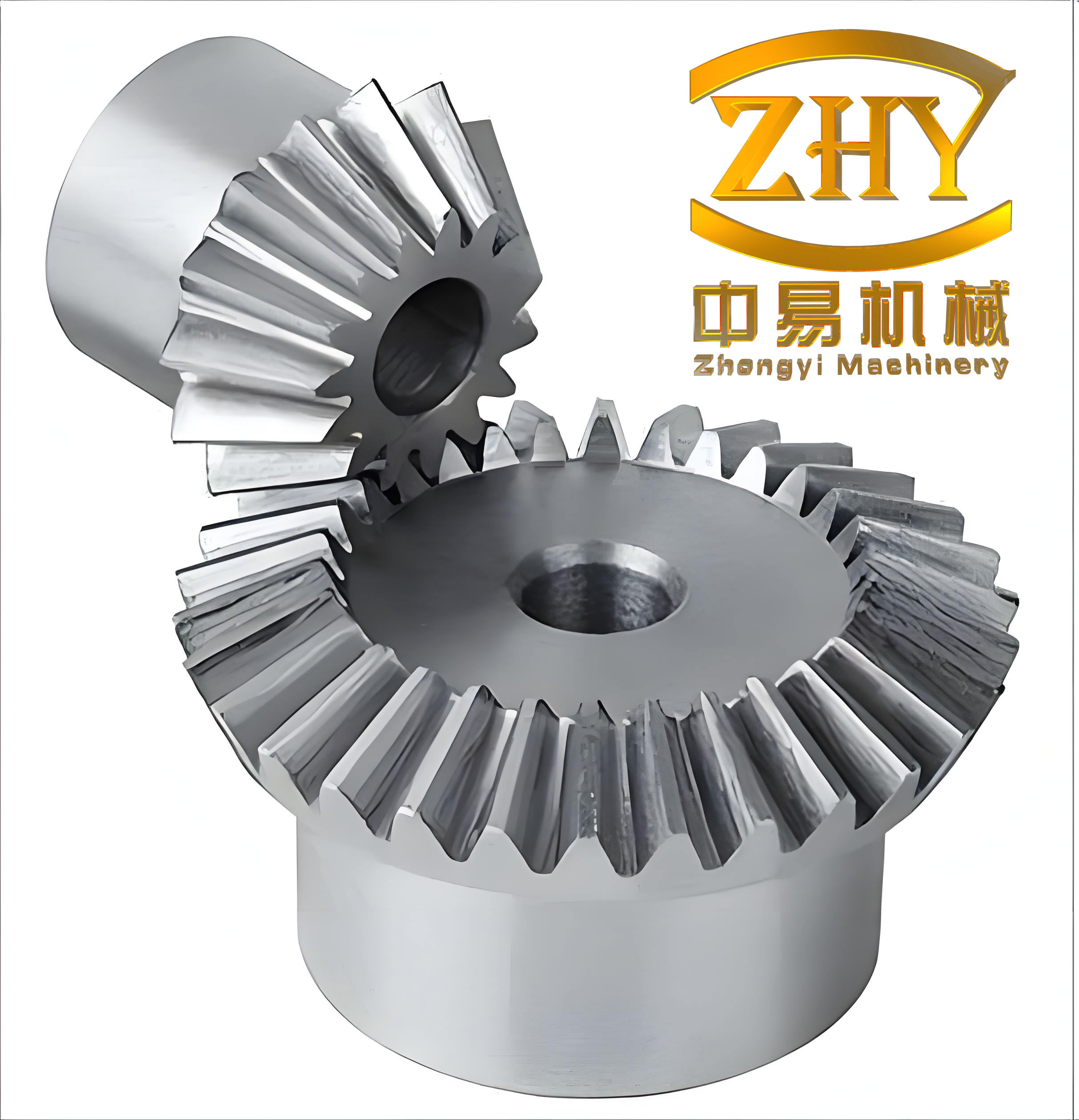
The straight bevel gear used in this work had 20 teeth, a module of 4 mm, a pressure angle of 20°, an addendum coefficient of 1, and a clearance coefficient of 0.3. The material was 40Cr steel, which is widely used for gears, shafts, and other machine elements that require a combination of strength, toughness, hardenability, and wear resistance. I kept the forging ratio constant at 7 for all trials so that the influence of forging temperature could be examined without the additional variable of total deformation. After forging, every straight bevel gear sample received the same heat treatment: oil quenching at 850 °C for 3 min, followed by tempering at 520 °C for 4 h. This identical post-forging treatment was essential because it allowed the wear behavior to be linked primarily to the forging temperature rather than to differences in quenching or tempering.
The wear tests were performed on a high-temperature friction and wear tester. I used a wheel speed of 250 r/min, a total wheel revolution count of 2 500 r, a relative sliding speed of 100 mm/min, a load of 100 N, and test temperatures of 25 °C and 300 °C. For each straight bevel gear sample, I recorded the wear volume. A smaller wear volume indicates better wear resistance, while a larger wear volume indicates worse wear resistance. I also examined the worn surfaces by scanning electron microscopy so that the quantitative wear volume could be connected with the visible damage modes, such as fine scratches, peeling, spalling, delamination, and material detachment. In my analysis, I treated the straight bevel gear as a tribological system in which the forging temperature changes the initial microstructure, and the test temperature changes the dynamic response of that microstructure under repeated contact.
The chemical composition of the 40Cr straight bevel gear material is summarized in Table 1. The composition range is typical for medium-carbon low-alloy steel, and the chromium content provides hardenability and contributes to the formation of carbides and tempered martensite after quenching and tempering. The carbon content allows the straight bevel gear to achieve a useful combination of core toughness and surface hardness after the selected heat treatment. The relatively low levels of sulfur and phosphorus are beneficial because they reduce the risk of hot cracking, cold cracking, and inclusion-related damage during forging and wear.
| Element | Mass percent range (%) | Role in the straight bevel gear |
|---|---|---|
| C | 0.37–0.44 | Controls hardenability, martensite hardness, and wear resistance |
| Si | 0.17–0.37 | Supports deoxidation and solid-solution strengthening |
| Mn | 0.50–0.80 | Improves hardenability and toughness |
| Cr | 0.80–1.10 | Increases hardenability, temper resistance, and carbide formation |
| Ni | ≤0.30 | Residual element, may improve toughness slightly |
| S | ≤0.035 | Impurity; high levels can reduce ductility |
| P | ≤0.035 | Impurity; high levels can increase embrittlement risk |
| Cu | ≤0.30 | Residual element with limited influence at this level |
The geometric parameters of the straight bevel gear are given in Table 2. These parameters define the contact kinematics, the sliding velocity distribution along the tooth flank, and the contact stress field. Even when the material and heat treatment are identical, a change in module, pressure angle, or tooth count can alter the wear response of a straight bevel gear. For this reason, I fixed the geometry for all samples and varied only the forging temperature. The constant geometry also made it possible to compare the wear volumes directly and to interpret the observed differences as being caused mainly by forging-induced microstructural changes.
| Parameter | Value | Influence on straight bevel gear behavior |
|---|---|---|
| Number of teeth | 20 | Affects contact ratio and load sharing |
| Module | 4 mm | Controls tooth size and bending strength |
| Pressure angle | 20° | Affects contact stress and sliding direction |
| Addendum coefficient | 1 | Defines tooth height and contact pattern |
| Clearance coefficient | 0.3 | Defines root clearance |
| Forging ratio | 7 | Controls total deformation and consolidation |
I designed the forging experiments so that the initial forging temperature could be studied independently from the final forging temperature. For the initial forging temperature series, I kept the final forging temperature at 860 °C and changed the initial forging temperature from 1 130 °C to 1 210 °C in steps of 20 °C. For the final forging temperature series, I kept the initial forging temperature at 1 170 °C and changed the final forging temperature from 820 °C to 880 °C in steps of 20 °C. The complete forging process matrix is shown in Table 3. This matrix allowed me to identify the individual effects of initial forging temperature and final forging temperature on the wear resistance of the straight bevel gear.
| Sample | Initial forging temperature (°C) | Final forging temperature (°C) | Forging ratio | Purpose |
|---|---|---|---|---|
| 1 | 1 130 | 860 | 7 | Low initial temperature condition |
| 2 | 1 150 | 860 | 7 | Lower intermediate initial temperature |
| 3 | 1 170 | 860 | 7 | Candidate optimum initial temperature |
| 4 | 1 190 | 860 | 7 | Upper intermediate initial temperature |
| 5 | 1 210 | 860 | 7 | High initial temperature condition |
| 6 | 1 170 | 820 | 7 | Low final temperature condition |
| 7 | 1 170 | 840 | 7 | Lower intermediate final temperature |
| 8 | 1 170 | 880 | 7 | High final temperature condition |
The heat treatment and wear test conditions are listed in Table 4. Because all straight bevel gear samples were quenched and tempered in the same way, the measured wear resistance reflects the combined effect of forging temperature and the subsequent heat treatment. The 520 °C tempering treatment produced a tempered martensitic or tempered bainitic structure with a balance of hardness and toughness. The wear test at 300 °C was included because many gears in service experience elevated temperatures due to friction, insufficient lubrication, or hot operating environments. At 300 °C, the straight bevel gear surface can experience thermal softening, oxide formation, and a change in the relative importance of adhesive and abrasive wear.
| Condition | Parameter |
|---|---|
| Quenching temperature | 850 °C |
| Quenching time | 3 min |
| Quenching medium | Oil |
| Tempering temperature | 520 °C |
| Tempering time | 4 h |
| Wear tester | High-temperature friction and wear tester |
| Wheel speed | 250 r/min |
| Total wheel revolutions | 2 500 r |
| Relative sliding speed | 100 mm/min |
| Normal load | 100 N |
| Test temperatures | 25 °C and 300 °C |
| Measured response | Wear volume |
To interpret the wear results, I used several standard wear descriptors. The wear volume is the primary measured quantity and is defined as the volume of material removed from the straight bevel gear surface during the test. If mass loss is measured, the wear volume can be calculated from the density and the mass difference. The corresponding expression is
$$V_w = \frac{\Delta m}{\rho}$$
where \(V_w\) is the wear volume, \(\Delta m\) is the mass loss, and \(\rho\) is the density of the straight bevel gear material. In this study, I used the directly recorded wear volume as the main indicator. The wear rate, which normalizes the wear volume by the applied load and the sliding distance, is written as
$$W_r = \frac{V_w}{F s}$$
where \(W_r\) is the dimensional wear rate, \(F\) is the normal load, and \(s\) is the sliding distance. A lower wear rate means that the straight bevel gear can tolerate more sliding distance before a given amount of material is removed. I also used the relative wear resistance, defined as the ratio of a reference wear volume to the wear volume of the sample under consideration:
$$R_w = \frac{V_{ref}}{V_w}$$
In this definition, a larger \(R_w\) indicates better wear resistance. When the reference is the best sample in the series, the relative wear resistance of the best straight bevel gear becomes 1, and all other samples have values below 1. This normalization is useful because it allows the performance of different straight bevel gear samples to be compared without depending on the absolute scale of the wear tester.
At the contact level, the wear behavior of the straight bevel gear can be related to the Archard wear equation, which is often written as
$$V_w = K \frac{F s}{H}$$
where \(K\) is the dimensionless wear coefficient, \(F\) is the normal load, \(s\) is the sliding distance, and \(H\) is the surface hardness. Rearranging this equation gives the wear coefficient:
$$K = \frac{V_w H}{F s}$$
This relationship shows that for a given load and sliding distance, a higher hardness usually reduces the wear volume, while a larger wear coefficient increases it. The wear coefficient itself depends on the microstructure, the presence of oxides, the lubrication state, the contact temperature, and the dominant wear mechanism. For the straight bevel gear, the forging temperature can change both \(H\) and \(K\), so the final wear volume is a combined response rather than a simple function of hardness alone.
Because the tests were conducted at 25 °C and 300 °C, I also considered the temperature dependence of the wear process. A common way to express the thermally activated nature of wear and microstructural evolution is the Arrhenius-type relation
$$K(T) = K_0 \exp\left(-\frac{Q}{RT}\right)$$
where \(K(T)\) is the temperature-dependent wear coefficient, \(K_0\) is a pre-exponential factor, \(Q\) is an activation energy, \(R\) is the universal gas constant, and \(T\) is the absolute temperature. At 300 °C, the value of \(T\) is higher, so thermally activated processes such as recovery, oxide growth, and dislocation rearrangement become more likely. These processes can either reduce wear by forming protective oxide layers or increase wear by softening the surface and promoting delamination. The measured results showed that the same forging temperature ranking was maintained at both test temperatures, but the absolute wear volume was larger at 300 °C than at 25 °C for the optimal straight bevel gear. This indicates that the forging process sets a microstructural baseline, while the test temperature shifts the entire wear curve upward.
The initial forging temperature had a strong influence on the wear resistance of the straight bevel gear. As the initial forging temperature increased from 1 130 °C to 1 210 °C, the wear resistance first improved, then remained nearly unchanged over a limited interval, and finally decreased sharply. This trend was observed at both 25 °C and 300 °C. The best wear resistance was obtained when the initial forging temperature was 1 170 °C. At this condition, the wear volume of the straight bevel gear was 21 × 10⁻³ mm³ at 25 °C and 48 × 10⁻³ mm³ at 300 °C. These values were the lowest in the initial forging temperature series. When the initial forging temperature was lower or higher than 1 170 °C, the wear volume increased, and the worn surface showed more severe damage.
| Initial forging temperature (°C) | Final forging temperature (°C) | Wear resistance at 25 °C | Wear resistance at 300 °C | Dominant observation |
|---|---|---|---|---|
| 1 130 | 860 | Poor | Poor | Extensive peeling and detachment |
| 1 150 | 860 | Improved | Improved | Moderate damage |
| 1 170 | 860 | Best | Best | Fine scratches, minimal peeling |
| 1 190 | 860 | Near best | Near best | Slight increase in damage |
| 1 210 | 860 | Sharp decline | Sharp decline | Local peeling and material loss |
The surface morphology observations supported the wear volume measurements. For the straight bevel gear forged with an initial forging temperature of 1 130 °C, the worn surface contained many peeled regions and detached flakes after testing at either 25 °C or 300 °C. This indicates that the subsurface microstructure was not sufficiently uniform or that the forging process did not provide enough deformation energy to close internal defects and refine the structure. For the straight bevel gear forged at 1 170 °C, the worn surface showed only fine scratches and no obvious peeling or detachment. This suggests that the surface could accommodate the contact stress and sliding action without large-scale delamination. For the straight bevel gear forged at 1 210 °C, the worn surface showed a small amount of peeling and detachment, so the damage was less severe than at 1 130 °C but clearly worse than at 1 170 °C. The same ranking was found at 25 °C and 300 °C.
The final forging temperature also played a decisive role in the wear resistance of the straight bevel gear. When the final forging temperature increased from 820 °C to 880 °C, the wear volume first decreased and then increased. The minimum wear volume again occurred at 860 °C. At this final forging temperature, the straight bevel gear had a wear volume of 21 × 10⁻³ mm³ at 25 °C and 48 × 10⁻³ mm³ at 300 °C. These values are identical to the best values obtained in the initial forging temperature series because the optimal initial temperature of 1 170 °C and the optimal final temperature of 860 °C define the same best condition. When the final forging temperature was lower than 860 °C, the straight bevel gear showed more severe wear. When the final forging temperature was higher than 860 °C, the wear also increased, but the damage was intermediate between the low-temperature and optimal conditions.
| Initial forging temperature (°C) | Final forging temperature (°C) | Wear resistance at 25 °C | Wear resistance at 300 °C | Dominant observation |
|---|---|---|---|---|
| 1 170 | 820 | Poor | Poor | Severe wear, peeling, detachment |
| 1 170 | 840 | Improved | Improved | Moderate wear |
| 1 170 | 860 | Best | Best | Fine scratches, stable surface |
| 1 170 | 880 | Decreased | Decreased | Some peeling and detachment |
The worn surface morphology for the final forging temperature series followed the same pattern as the wear volume results. At a final forging temperature of 820 °C, the straight bevel gear surface showed extensive peeling and detachment after wear testing at 25 °C and 300 °C. This suggests that the final forging temperature was too low, so the material experienced insufficient deformation and possibly cold hardening near the end of forging. At a final forging temperature of 860 °C, the worn surface had only fine scratches and no obvious peeling or detachment. This indicates that the straight bevel gear reached a favorable combination of deformation, recrystallization, and microstructure refinement. At a final forging temperature of 880 °C, the worn surface again showed some peeling and detachment, which is consistent with overheating and grain coarsening. Therefore, the final forging temperature should not be too low or too high, and 860 °C is the preferred value for the straight bevel gear in this study.
I explain the observed wear behavior in terms of three stages of friction and wear for the straight bevel gear. In the initial stage, the applied load creates high contact stresses between the worn wheel and the gear surface. The straight bevel gear surface undergoes plastic flow, and sliding or scratching marks appear. In the stable stage, the contact conditions become more uniform, and the wear rate becomes relatively steady. In the accelerated stage, accumulated damage leads to subsurface crack initiation, crack propagation, and eventual material detachment. A straight bevel gear with poor wear resistance enters the accelerated stage earlier and shows more peeling and spalling. A straight bevel gear with good wear resistance remains in the stable stage longer and exhibits only fine scratches.
The wear volume as a function of time can be idealized in a piecewise form. During the running-in stage, the volume may increase rapidly:
$$V(t) = V_0 + k_i t, \quad 0 \le t \le t_i$$
During the steady wear stage, the increase is slower and approximately linear:
$$V(t) = V_i + k_s (t – t_i), \quad t_i \le t \le t_s$$
During the accelerated wear stage, the slope increases:
$$V(t) = V_s + k_a (t – t_s), \quad t \ge t_s$$
where \(k_i\), \(k_s\), and \(k_a\) are the wear rates in the initial, steady, and accelerated stages, respectively. In my experiments, the straight bevel gear forged at 1 170 °C and 860 °C had the lowest \(k_s\) and the longest delay before accelerated wear. The straight bevel gear forged at 1 130 °C or 820 °C entered the accelerated stage earlier, which produced a larger final wear volume and more visible surface damage.
| Wear stage | Characteristic | Straight bevel gear response |
|---|---|---|
| Initial stage | High local stress and plastic flow | Scratches and sliding marks |
| Stable stage | Uniform contact and slow material loss | Fine wear tracks, low wear rate |
| Accelerated stage | Crack growth and material detachment | Peeling, spalling, and large wear volume |
The influence of the initial forging temperature can be understood through the balance between deformation energy and grain growth. If the initial forging temperature is too low, the straight bevel gear does not receive enough thermal energy for uniform deformation. The material may have high flow stress, and the deformation may be concentrated in localized regions. This can leave residual porosity, uneven microstructure, and internal defects that later act as crack initiation sites during wear. As a result, the straight bevel gear has poor wear resistance. When the initial forging temperature increases toward 1 170 °C, the material becomes softer and more ductile, the deformation becomes more uniform, and the microstructure becomes denser and more homogeneous. This improves the load-bearing capacity of the straight bevel gear and reduces wear. If the initial forging temperature becomes too high, the prior austenite grains grow rapidly, and the final microstructure becomes coarse. A coarse microstructure has less grain-boundary strengthening and a lower resistance to plastic deformation and crack propagation. Therefore, the straight bevel gear wear resistance decreases sharply at 1 210 °C.
Grain growth during high-temperature forging can be described by a general kinetic equation:
$$d^n – d_0^n = A t \exp\left(-\frac{Q_g}{RT}\right)$$
where \(d\) is the average grain size, \(d_0\) is the initial grain size, \(n\) is the grain growth exponent, \(A\) is a material constant, \(t\) is time, \(Q_g\) is the activation energy for grain growth, \(R\) is the gas constant, and \(T\) is the absolute temperature. This equation shows that grain size increases with temperature and time. For the straight bevel gear, excessive initial forging temperature causes \(d\) to increase, and the coarser grains reduce the resistance to wear. The Hall–Petch relationship further connects grain size to strength:
$$\sigma_y = \sigma_0 + k_y d^{-1/2}$$
where \(\sigma_y\) is the yield strength, \(\sigma_0\) is the friction stress, and \(k_y\) is the strengthening coefficient. A larger grain size reduces \(\sigma_y\), which in turn reduces the ability of the straight bevel gear to resist plastic deformation under contact loading. Because wear resistance is strongly influenced by the ability to avoid plastic flow and crack initiation, the coarse-grained straight bevel gear forged at an excessively high initial temperature exhibits poor wear resistance.
| Initial forging condition | Microstructural tendency | Effect on straight bevel gear wear |
|---|---|---|
| Too low | Insufficient deformation, uneven structure, possible defects | Poor wear resistance, peeling, detachment |
| Optimal | Uniform deformation, refined and homogeneous structure | Best wear resistance, fine scratches only |
| Too high | Grain coarsening, lower boundary strengthening | Reduced wear resistance, local peeling |
The final forging temperature controls the condition of the straight bevel gear at the end of deformation. If the final forging temperature is too low, the material has limited plasticity, the deformation resistance is high, and cold hardening can occur. This may increase surface hardness locally, but it also introduces residual stresses and microcracks that are detrimental to wear resistance. The straight bevel gear may appear hard but brittle, and under repeated sliding contact it can develop peeling and detachment. If the final forging temperature is too high, the straight bevel gear may overheat, and the microstructure can coarsen. Overheating also reduces the benefit of deformation-induced refinement and can produce a softer, less stable surface. Therefore, the final forging temperature must be kept in a narrow window. In my experiments, 860 °C gave the best balance between sufficient plasticity and controlled microstructure.
The final forging temperature can also affect the stored deformation energy. The stored energy can be approximated as
$$E_s = \int \sigma \, d\epsilon – Q_r$$
where \(E_s\) is the stored energy, \(\sigma\) is the flow stress, \(\epsilon\) is the strain, and \(Q_r\) is the energy released by recovery and recrystallization. At a low final forging temperature, recovery and recrystallization are limited, so a large amount of stored energy remains in the straight bevel gear. This can lead to an unstable microstructure and increased susceptibility to crack initiation during wear. At an excessively high final forging temperature, recovery and recrystallization may proceed too far, and grain growth may occur, which again reduces wear resistance. The optimum final forging temperature provides enough thermal activation for beneficial recrystallization without causing excessive grain growth.
At 300 °C, the wear volume of the straight bevel gear was larger than at 25 °C, even for the optimal forging condition. The increase from 21 × 10⁻³ mm³ at 25 °C to 48 × 10⁻³ mm³ at 300 °C is more than a factor of two. This shows that elevated temperature degrades the wear resistance of the straight bevel gear. The main reasons are thermal softening, increased oxidation, and a change in the contact stress distribution. Thermal softening reduces the hardness \(H\), and according to the Archard relation, a lower hardness increases the wear volume for the same load and sliding distance. Oxidation can produce oxide layers that may either protect the surface or break down into abrasive debris. If the oxide layer is stable and adherent, it can reduce metal-to-metal contact. If the oxide layer is brittle and easily removed, it can accelerate wear by producing hard oxide particles. In my tests, the worn surfaces at 300 °C showed more damage than those at 25 °C, which suggests that the protective effect of oxidation was not sufficient to offset thermal softening and microstructural degradation.
The temperature dependence of hardness can be written in a simplified form as
$$H(T) = H_0 \exp\left[-\alpha (T – T_0)\right]$$
where \(H(T)\) is the hardness at temperature \(T\), \(H_0\) is the hardness at a reference temperature \(T_0\), and \(\alpha\) is a softening coefficient. A higher test temperature reduces \(H(T)\), which tends to increase the wear volume. For the straight bevel gear, the forging temperature determines the initial hardness and the stability of the tempered microstructure. The optimal forging condition produces a microstructure that resists softening better than the low-temperature or high-temperature forging conditions. This is why the ranking of the straight bevel gear samples remained similar at 25 °C and 300 °C, but the absolute wear volume was larger at 300 °C.
| Test temperature | Main additional effect | Consequence for straight bevel gear |
|---|---|---|
| 25 °C | Mechanical contact and mild oxidation | Lower wear volume, clearer effect of forging microstructure |
| 300 °C | Thermal softening, oxidation, possible oxide debris | Higher wear volume, same optimum forging window |
The optimization of forging temperature for the straight bevel gear can be expressed as a multi-objective problem. I want to minimize the wear volume at 25 °C and 300 °C simultaneously. A convenient objective function is
$$J(T_i, T_f) = w_{25} \frac{V_{25}(T_i, T_f)}{V_{25,ref}} + w_{300} \frac{V_{300}(T_i, T_f)}{V_{300,ref}}$$
where \(T_i\) is the initial forging temperature, \(T_f\) is the final forging temperature, \(V_{25}\) and \(V_{300}\) are the wear volumes at the two test temperatures, \(V_{25,ref}\) and \(V_{300,ref}\) are reference wear volumes, and \(w_{25}\) and \(w_{300}\) are weighting factors. If room-temperature performance is more important, \(w_{25}\) can be increased. If elevated-temperature performance is more important, \(w_{300}\) can be increased. In this study, the same optimum was obtained for both test temperatures, so the weighting factors do not change the preferred forging window. The optimal condition is
$$T_i^* = 1\,170\,^\circ\text{C}, \quad T_f^* = 860\,^\circ\text{C}$$
Under this condition, the straight bevel gear achieved the smallest wear volume at both 25 °C and 300 °C. The corresponding measured wear volumes were
$$V_{25}^* = 21 \times 10^{-3}\,\text{mm}^3$$
$$V_{300}^* = 48 \times 10^{-3}\,\text{mm}^3$$
These values provide a practical benchmark for the straight bevel gear produced by the forging process. They also show that the elevated-temperature wear volume is about 2.29 times the room-temperature wear volume:
$$\frac{V_{300}^*}{V_{25}^*} = \frac{48}{21} \approx 2.29$$
This ratio is useful because it quantifies the thermal penalty for the straight bevel gear under the selected testing conditions. If a design requires a certain wear life at 300 °C, the room-temperature wear volume alone is not sufficient for prediction, and the elevated-temperature ratio must be included.
| Optimization item | Value | Comment |
|---|---|---|
| Optimal initial forging temperature | 1 170 °C | Best combination of deformation uniformity and grain control |
| Optimal final forging temperature | 860 °C | Best balance of plasticity, recrystallization, and microstructure |
| Wear volume at 25 °C | 21 × 10⁻³ mm³ | Lowest in the test matrix |
| Wear volume at 300 °C | 48 × 10⁻³ mm³ | Lowest in the test matrix |
| Elevated-to-room wear ratio | ≈2.29 | Quantifies thermal penalty |
The process window for the straight bevel gear can be summarized by upper and lower limits. The initial forging temperature should be high enough to ensure uniform deformation and microstructural homogenization, but low enough to avoid grain coarsening. The final forging temperature should be high enough to avoid cold hardening and cracking, but low enough to avoid overheating and grain growth. Based on the experimental trends, I can define a practical window around the optimum. The initial forging temperature should remain close to 1 170 °C, and temperatures below 1 150 °C or above 1 190 °C are less favorable. The final forging temperature should remain close to 860 °C, and temperatures below 840 °C or above 880 °C are less favorable. This window is not a sharp threshold but a region where the straight bevel gear is expected to maintain good wear resistance at both room and elevated temperatures.
| Process variable | Less favorable low side | Preferred value | Less favorable high side |
|---|---|---|---|
| Initial forging temperature | 1 130–1 150 °C | 1 170 °C | 1 190–1 210 °C |
| Final forging temperature | 820–840 °C | 860 °C | 880 °C |
From a production perspective, the straight bevel gear forging process should be controlled with attention to both temperature and time. Temperature alone is not sufficient because grain growth depends on time as well as temperature. A long dwell at a high initial forging temperature can produce the same harmful grain coarsening as a shorter dwell at an even higher temperature. Similarly, a final forging temperature that is acceptable under a short forging cycle may become detrimental if the straight bevel gear remains hot for a long time after deformation. Therefore, the optimal forging parameters should be implemented together with controlled heating rates, transfer times, and cooling rates. The heat treatment after forging must also be kept consistent, because the quench and temper response of the straight bevel gear depends on the prior microstructure produced during forging.
The wear mechanisms observed in this study can be divided into abrasive wear, adhesive wear, oxidative wear, and delamination wear. Abrasive wear occurs when hard particles or asperities cut or plow the surface. Adhesive wear occurs when asperities weld and then rupture, transferring material from one surface to another. Oxidative wear occurs when surface oxides form and are removed. Delamination wear occurs when subsurface cracks propagate and eventually cause sheet-like material removal. For the straight bevel gear, the dominant mechanism depends on the forging temperature, the test temperature, and the local contact conditions. The low-temperature forged straight bevel gear showed more delamination and peeling, which suggests that subsurface defects and uneven microstructure promoted crack initiation. The optimally forged straight bevel gear showed fine scratches, which suggests a more stable combination of mild abrasive and oxidative wear. The high-temperature forged straight bevel gear showed local peeling, which suggests that grain coarsening and reduced boundary strength allowed cracks to form and propagate.
| Wear mechanism | Typical surface feature | Relation to straight bevel gear forging |
|---|---|---|
| Abrasive wear | Scratches, grooves, plowing | Hard debris or asperities; reduced by uniform hardness |
| Adhesive wear | Local transfer, smearing, tearing | Metal-to-metal contact; influenced by surface energy and hardness |
| Oxidative wear | Oxide films, compacted oxide debris | More important at 300 °C; depends on microstructure stability |
| Delamination wear | Peeling, spalling, sheet-like detachment | Promoted by defects, coarse grains, and subsurface cracks |
The relationship between microstructure and wear resistance can be summarized through several equations. The hardness contribution is represented by
$$V_w \propto \frac{1}{H^m}$$
where \(m\) is an exponent that depends on the wear mechanism. The grain-size contribution can be represented through the Hall–Petch relation, which shows that a smaller grain size increases strength. The defect contribution can be represented by a damage parameter \(D\):
$$V_w \propto D \, F \, s$$
where \(D\) increases with porosity, inclusions, microcracks, and microstructural heterogeneity. The forging temperature affects \(H\), \(D\), and the grain size simultaneously. A low initial forging temperature may increase \(D\) because of incomplete deformation and residual defects. A high initial forging temperature may decrease the strength by increasing grain size. The optimal forging temperature minimizes the combined effect of \(D\) and grain coarsening while maintaining sufficient hardness. Similarly, a low final forging temperature may increase \(D\) through cold hardening and cracking, while a high final forging temperature may reduce \(H\) through overheating and grain growth. The optimum at 860 °C provides the best compromise.
I also considered the effect of contact pressure on the straight bevel gear. The nominal contact pressure is
$$p = \frac{F}{A_c}$$
where \(p\) is the contact pressure, \(F\) is the normal load, and \(A_c\) is the real contact area. For a rough surface, \(A_c\) is much smaller than the apparent area, so local pressures can be very high. The straight bevel gear with a uniform, fine-grained microstructure can distribute the load over a larger real contact area, which reduces the local pressure and delays the transition to accelerated wear. The straight bevel gear with coarse grains or defects has a more irregular contact response, which can concentrate stress and promote peeling. This is another reason why the optimally forged straight bevel gear performed better at both 25 °C and 300 °C.
The flash temperature at the contact interface can be approximated as
$$T_f = T_b + \Delta T_f$$
where \(T_f\) is the flash temperature, \(T_b\) is the bulk temperature, and \(\Delta T_f\) is the temperature rise caused by frictional heating. At a test temperature of 300 °C, the bulk temperature is already high, so the flash temperature can reach even higher values. This can cause local softening, oxide formation, and microstructural change. The forging process determines how well the straight bevel gear resists these local thermal transients. A stable tempered microstructure with fine grains and uniform hardness is more resistant to flash-temperature softening than a coarse or defective microstructure. Thus, the forging temperature indirectly controls the high-temperature wear resistance of the straight bevel gear.
In my assessment, the initial forging temperature and final forging temperature should not be selected independently. They interact through the total thermomechanical history of the straight bevel gear. The initial forging temperature controls the starting microstructure and the ease of deformation, while the final forging temperature controls the finishing microstructure and the amount of stored energy. A high initial forging temperature followed by a low final forging temperature may produce a different combination of grain size and residual stress than a low initial forging temperature followed by a high final forging temperature. For the straight bevel gear, the best combination in this study was 1 170 °C initial and 860 °C final. This combination gave the lowest wear volume at both test temperatures and the least severe surface damage.
The interaction can be represented qualitatively by a response surface:
$$V_w(T_i, T_f) = \beta_0 + \beta_1 T_i + \beta_2 T_f + \beta_{11} T_i^2 + \beta_{22} T_f^2 + \beta_{12} T_i T_f$$
where \(V_w(T_i, T_f)\) is the wear volume, and the \(\beta\) terms are model coefficients. In a full response surface study, the coefficients would be fitted from experimental data. For the present investigation, the observed trends indicate that both quadratic terms are positive, which produces minima with respect to both forging temperatures. The interaction term \(\beta_{12} T_i T_f\) can shift the location of the minimum and change the curvature of the response surface. Even without a full numerical fit, the experimental evidence is sufficient to show that the minimum lies near \(T_i = 1\,170\,^\circ\text{C}\) and \(T_f = 860\,^\circ\text{C}\).
A one-dimensional approximation for the initial forging temperature can be written as
$$V_i(T_i) = a_i (T_i – T_i^*)^2 + V_i^*$$
where \(V_i^*\) is the minimum wear volume and \(T_i^*\) is the optimal initial forging temperature. Similarly, for the final forging temperature,
$$V_f(T_f) = a_f (T_f – T_f^*)^2 + V_f^*$$
where \(V_f^*\) is the minimum wear volume and \(T_f^*\) is the optimal final forging temperature. These parabolic approximations capture the first-increase-then-decrease or first-decrease-then-increase behavior in a simple mathematical form. In the actual process, the curve is not perfectly parabolic because of the plateau observed in the initial forging temperature series, but the general shape is useful for process optimization.
| Model element | Meaning | Practical interpretation for straight bevel gear |
|---|---|---|
| \(T_i^*\) | Optimal initial forging temperature | 1 170 °C in this study |
| \(T_f^*\) | Optimal final forging temperature | 860 °C in this study |
| \(V_i^*\) | Minimum wear volume for initial temperature series | 21 × 10⁻³ mm³ at 25 °C and 48 × 10⁻³ mm³ at 300 °C |
| \(V_f^*\) | Minimum wear volume for final temperature series | Same values at the combined optimum |
| \(a_i, a_f\) | Curvature coefficients | Larger values indicate sharper sensitivity to temperature deviation |
The practical implications for manufacturing a straight bevel gear are clear. First, the forging temperature should be treated as a quality-critical parameter rather than an approximate operating variable. Small deviations from the optimum can increase wear volume and reduce service life. Second, the initial and final forging temperatures should be controlled within a narrow window. Third, the heat treatment after forging must be matched to the forging condition. If the forging temperature produces a coarse microstructure, the quench and temper treatment may not fully recover the lost wear resistance. Fourth, the testing temperature should be considered during design. A straight bevel gear that performs well at room temperature may still experience a large increase in wear volume at 300 °C, and the design must account for this thermal penalty. Fifth, the worn surface morphology should be used as a diagnostic tool. Fine scratches indicate stable wear, while peeling and detachment indicate an unfavorable microstructure or forging condition.
| Manufacturing recommendation | Reason | Expected benefit for straight bevel gear |
|---|---|---|
| Use initial forging temperature near 1 170 °C | Promotes uniform deformation and avoids coarse grains | Lower wear volume at 25 °C and 300 °C |
| Use final forging temperature near 860 °C | Balances plasticity and microstructure control | Minimal peeling and stable wear surface |
| Keep forging ratio constant | Isolates temperature effects | More reliable process comparison |
| Maintain identical quench and temper | Preserves comparability | Wear differences reflect forging history |
| Inspect worn surfaces | Links quantitative wear to damage mode | Early detection of unfavorable forging conditions |
I also note that the wear resistance of the straight bevel gear is not determined by a single property. Hardness, toughness, grain size, inclusion content, residual stress, and surface integrity all contribute. A very hard but brittle straight bevel gear may resist indentation but crack under repeated sliding. A very tough but soft straight bevel gear may deform plastically and wear rapidly. The optimal forging temperature produces a balanced microstructure that combines sufficient hardness with adequate toughness and microstructural uniformity. This balance is why the straight bevel gear forged at 1 170 °C and 860 °C showed the best overall performance. It did not simply have the highest hardness; it had the most favorable combination of properties for the tribological loading conditions.
The effect of test temperature can be further understood by comparing the wear volumes at 25 °C and 300 °C. If the wear volume at 300 °C is much larger than at 25 °C, the material is sensitive to thermal softening and oxidation. If the ratio is small, the material is thermally stable. For the optimal straight bevel gear, the ratio was about 2.29. For less favorable forging conditions, the ratio may be even larger, although the exact values depend on the wear mechanism transition. In general, a higher ratio indicates that the straight bevel gear should be protected by cooling, lubrication, or surface treatment in high-temperature service. The forging process can improve the ratio by producing a more stable microstructure, but it cannot eliminate the inherent effect of temperature on wear.
| Quantity | Symbol | Interpretation |
|---|---|---|
| Wear volume at 25 °C | \(V_{25}\) | Room-temperature material loss |
| Wear volume at 300 °C | \(V_{300}\) | Elevated-temperature material loss |
| Thermal wear ratio | \(V_{300}/V_{25}\) | Degree of thermal penalty |
| Relative wear resistance | \(R_w\) | Normalized comparison between samples |
| Wear rate | \(W_r\) | Volume loss per unit load and distance |
| Wear coefficient | \(K\) | Material and contact efficiency parameter |
From a statistical viewpoint, the experiments can be treated as a two-factor study with temperature levels selected around a central condition. The initial forging temperature factor had five levels, and the final forging temperature factor had four levels. The response was the wear volume at two test temperatures. A full factorial design would require twenty combinations, but the present study used a selected subset to focus on the most influential ranges. This is a practical approach when the goal is to identify an optimum rather than to estimate all interaction coefficients. If a full response surface were desired, additional combinations such as 1 150 °C with 840 °C, 1 190 °C with 880 °C, and other intermediate points could be added. The present data are sufficient to show that the optimum lies near 1 170 °C and 860 °C and that the wear resistance deteriorates when the straight bevel gear is forged too cold or too hot.
The variation of wear volume with forging temperature can also be linked to the concept of process capability. In manufacturing, the forging temperature is not perfectly constant. There is a distribution around the set point. If the process window is narrow, small fluctuations can produce a significant fraction of straight bevel gears with poor wear resistance. If the process window is wide, the manufacturing process is more robust. The results suggest that the initial forging temperature should be controlled more tightly than the final forging temperature when the deviation is on the high side, because the sharp decline at 1 210 °C indicates a strong sensitivity to overheating. The final forging temperature also has a clear optimum, but the degradation on the high side was intermediate rather than catastrophic. In both cases, the best strategy is to maintain the temperature near the optimum and to avoid excursions that promote either incomplete deformation or grain coarsening.
I can express the process capability index for the straight bevel gear as
$$C_p = \frac{USL – LSL}{6\sigma}$$
where \(USL\) and \(LSL\) are the upper and lower specification limits for forging temperature, and \(\sigma\) is the standard deviation of the process. A higher \(C_p\) means that the process is more capable of staying within the preferred window. If the specification limits are set at 1 150 °C and 1 190 °C for the initial forging temperature, and at 840 °C and 880 °C for the final forging temperature, then the process must be tightly controlled to achieve a high \(C_p\). This is especially important for the straight bevel gear because wear resistance is a safety-related and life-limiting property in many transmission systems.
The surface damage observations can be organized into a severity ranking. At the least severe level, the worn surface shows fine scratches and a smooth appearance. At the next level, the surface shows moderate scratching and minor plastic deformation. At the next level, the surface shows local peeling and small detached flakes. At the most severe level, the surface shows extensive peeling, spalling, and large detached regions. In this study, the optimal straight bevel gear remained at the least severe level at both 25 °C and 300 °C. The low-temperature forged straight bevel gear and the low-final-temperature forged straight bevel gear reached the most severe level. The high-temperature forged straight bevel gear and the high-final-temperature forged straight bevel gear reached the intermediate or next-to-most-severe level. This ranking is consistent with the wear volume data and supports the conclusion that 1 170 °C and 860 °C are the preferred forging temperatures.
| Damage level | Surface appearance | Wear volume tendency | Straight bevel gear condition |
|---|---|---|---|
| 1 | Fine scratches, smooth surface | Lowest | Optimal forging condition |
| 2 | Moderate scratches, minor plastic flow | Low to moderate | Slightly off-optimum |
| 3 | Local peeling, small flakes | Moderate to high | High-side temperature deviation |
| 4 | Extensive peeling, spalling, detachment | Highest | Low-side temperature deviation |
The results also imply that the straight bevel gear forging process should be designed with a defined cooling path after the final forging pass. If the straight bevel gear cools too slowly, the effective time at high temperature is increased, which can promote grain growth even if the final forging temperature itself is acceptable. If the straight bevel gear cools too quickly, residual stresses and cracking may occur. The cooling path is therefore an extension of the forging temperature control. In the present study, all samples received the same subsequent heat treatment, which means the cooling after forging and the quench and temper were standardized. In industrial production, the cooling path should be included in the process specification along with the initial and final forging temperatures.
I further note that the test load of 100 N and the sliding speed of 100 mm/min are moderate but representative of certain geared transmission contacts. A higher load would increase the contact pressure and accelerate wear, especially for the straight bevel gear with a coarse or defective microstructure. A higher sliding speed would increase frictional heating and flash temperature, which could shift the wear mechanism toward oxidative and thermal softening modes. Therefore, the optimal forging window identified here should be validated for specific application conditions. Nevertheless, the relative ranking of the straight bevel gear samples is likely to remain similar because the forging temperature controls the fundamental microstructure. The optimal condition provides the best starting point for further optimization of load, speed, lubrication, and surface treatment.
The use of 40Cr steel for the straight bevel gear is advantageous because it can be forged, machined, quenched, and tempered with well-established processes. The chromium content improves hardenability, which helps the straight bevel gear achieve a uniform hardness after quenching. However, high hardenability also means that the cooling rate must be controlled to avoid cracking. The tempering treatment at 520 °C reduces brittleness and produces a microstructure that can withstand contact fatigue and wear. The forging temperature must be compatible with this heat treatment. If the forging temperature is too high, the coarse grains may not be fully refined by the quench and temper treatment. If the forging temperature is too low, the uneven microstructure may lead to nonuniform hardening and residual stress. The optimal forging condition therefore supports the subsequent heat treatment rather than conflicting with it.
The relationship between wear resistance and service life can be expressed as
$$L = \frac{V_{allow}}{W_r}$$
where \(L\) is the wear life, \(V_{allow}\) is the allowable wear volume, and \(W_r\) is the wear rate. For a given allowable wear volume, a lower wear rate directly increases the service life of the straight bevel gear. The optimal forging condition reduces \(W_r\), so it extends \(L\). This equation is simple but useful because it connects the laboratory wear volume to the practical life of the straight bevel gear. If the wear rate at 300 °C is about 2.29 times the wear rate at 25 °C for the same sliding distance and load, then the allowable wear volume must be larger or the service time must be shorter at 300 °C. Designers should therefore account for the thermal wear ratio when specifying the straight bevel gear for high-temperature applications.
| Performance indicator | Better direction | Meaning for straight bevel gear |
|---|---|---|
| Wear volume | Lower | Less material loss |
| Wear rate | Lower | Longer service life |
| Relative wear resistance | Higher | Better performance compared with reference |
| Thermal wear ratio | Lower | Less sensitivity to elevated temperature |
| Damage severity | Lower | Fewer peeling and spalling defects |
The initial forging temperature of 1 170 °C can be interpreted as the point where the straight bevel gear has enough thermal activation for recrystallization and uniform deformation but not enough for rapid grain growth. The final forging temperature of 860 °C can be interpreted as the point where the straight bevel gear finishes deformation with a refined and stable microstructure but without cold hardening or overheating. Together, these two temperatures define a thermomechanical processing route that produces a straight bevel gear with excellent wear resistance at both room and elevated temperatures. The results also show that the wear resistance is not monotonic with temperature. Increasing the forging temperature does not always improve performance, and decreasing it does not always increase hardness in a beneficial way. The optimum is a balance, and the balance is best identified experimentally.
In my view, the most important practical conclusion is that the straight bevel gear should be forged within a narrow temperature window rather than at a single arbitrary temperature chosen from experience. The experimental data show that moving away from the optimum by only 20 °C can change the wear resistance. For example, the initial forging temperature series included 1 150 °C, 1 170 °C, and 1 190 °C, and the best result was at the center. The final forging temperature series included 840 °C, 860 °C, and 880 °C, and again the best result was at the center. This symmetry suggests that the optimum is well defined and that the process should be centered on 1 170 °C and 860 °C. The use of a center point also provides a reference for process control and quality assurance.
The wear test results at 25 °C and 300 °C can be summarized in a single comparison table. The optimal straight bevel gear had the lowest wear volume at both temperatures. The low-temperature forging conditions produced the highest wear volumes and the most severe surface damage. The high-temperature forging conditions produced intermediate wear volumes and less severe damage than the low-temperature conditions but still worse than the optimum. This summary is consistent across the initial forging temperature and final forging temperature series. It provides strong evidence that the optimal forging condition is not an artifact of one test temperature but a genuine process optimum.
| Condition | 25 °C wear resistance | 300 °C wear resistance | Overall ranking |
|---|---|---|---|
| Initial 1 130 °C, final 860 °C | Poor | Poor | Lowest |
| Initial 1 150 °C, final 860 °C | Improved | Improved | Intermediate |
| Initial 1 170 °C, final 860 °C | Best | Best | Highest |
| Initial 1 190 °C, final 860 °C | Near best | Near best | High |
| Initial 1 210 °C, final 860 °C | Sharp decline | Sharp decline | Low |
| Initial 1 170 °C, final 820 °C | Poor | Poor | Lowest |
| Initial 1 170 °C, final 840 °C | Improved | Improved | Intermediate |
| Initial 1 170 °C, final 880 °C | Decreased | Decreased | Low to intermediate |
Finally, I conclude that the forging temperature has a significant and systematic effect on the wear resistance of the straight bevel gear. The initial forging temperature and final forging temperature should both be optimized. The initial forging temperature should be high enough to ensure uniform deformation and microstructure refinement but not so high that grain coarsening occurs. The final forging temperature should be high enough to avoid cold hardening and cracking but not so high that overheating and grain growth occur. In this study, the optimal initial forging temperature was 1 170 °C, and the optimal final forging temperature was 860 °C. Under this condition, the straight bevel gear achieved the lowest wear volume at both 25 °C and 300 °C: 21 × 10⁻³ mm³ at 25 °C and 48 × 10⁻³ mm³ at 300 °C. The worn surface showed only fine scratches, without obvious peeling or detachment. These findings provide a practical basis for improving the wear resistance and service life of the straight bevel gear in industrial production.
The broader significance of this work is that the straight bevel gear should be considered as a thermomechanically processed component. Its wear resistance is not only a surface property but a consequence of the entire manufacturing chain, including heating, forging, cooling, quenching, and tempering. The forging temperature is a central link in this chain because it determines the starting condition for all subsequent steps. By controlling the initial and final forging temperatures within the optimized window, manufacturers can produce a straight bevel gear with a more uniform microstructure, better dimensional stability, lower wear volume, and longer service life. The same logic can be extended to other gear types and other medium-carbon alloy steels, although the exact optimum temperatures may differ. For the 40Cr straight bevel gear investigated here, the preferred forging temperatures are 1 170 °C initial and 860 °C final.
I also recommend that future work include hardness mapping, residual stress measurement, electron backscatter diffraction, and transmission electron microscopy to quantify the microstructural changes caused by the forging temperature. These methods would allow the wear volume to be directly correlated with grain size, dislocation density, carbide distribution, and oxide scale characteristics. A full response surface design with more temperature levels and more replication would also improve the statistical confidence. In addition, wear testing under different loads, speeds, lubricants, and surface treatments would help determine whether the optimal forging window remains the same under other service conditions. Such work would further strengthen the design and manufacturing guidelines for the straight bevel gear.
In summary, my first-person experimental investigation shows that the wear resistance of the straight bevel gear is highly sensitive to forging temperature. The initial forging temperature should be near 1 170 °C, and the final forging temperature should be near 860 °C. At these values, the straight bevel gear exhibits the smallest wear volume at both 25 °C and 300 °C and the least severe surface damage. Deviations toward lower temperatures cause insufficient deformation, cold hardening, and severe peeling, while deviations toward higher temperatures cause grain coarsening, reduced strength, and increased wear. The results provide clear evidence that forging temperature optimization is an effective way to improve the wear resistance and service reliability of the straight bevel gear.