
I begin this analysis from the functional requirements of a new energy vehicle transmission, where a ZN-type screw gear pair performs speed reduction and torque multiplication in an electromechanical shift actuator. In my process planning, the screw gear pair is not treated as a simple pair of rotating parts; instead, I treat the screw gear as a coupled system of geometry, material, heat treatment, tooling, fixture design, and metrology. The screw gear mechanism used here is a cylindrical screw gear drive with a 90° shaft angle. I selected a ZN-type screw gear, also called a normal plane straight-sided screw gear, because its tooth surface is a ruled surface generated by a straight line moving helically relative to the screw gear axis. This makes the screw gear suitable for precision forming, grinding, and inspection when the process chain is properly controlled.
In the new energy vehicle transmission, the screw gear pair is used in several actuator branches. The select motor drives a screw gear reducer to reduce speed and increase torque, then a rack-and-pinion system converts rotation into linear motion and pulls the shift control shaft. The shift motor drives another screw gear reducer and then a single-stage gear mechanism to transmit power to the shift shaft. The clutch control motor also uses a screw gear reducer, and the self-locking behavior of the screw gear system allows the clutch to remain disengaged for a long time. Because these functions are safety-related and comfort-related, the screw gear pair must have high kinematic accuracy, stable backlash, low noise, and reliable self-locking. Therefore, my machining process for the screw gear must satisfy both dimensional tolerances and functional requirements.
The screw gear pair in this application is an interleaved screw gear and worm wheel arrangement inside a bearing housing. It belongs to the general cylindrical screw gear drive category. The shaft angle is nominally 90°. The screw gear has a large transmission ratio, a compact structure, multiple teeth in mesh, high contact ratio, smooth transmission, and low noise. However, the screw gear and its mating worm wheel are difficult to machine, and the process requirements are strict. I developed the process route by first analyzing the screw gear geometry, then the worm wheel geometry, then the tooling and inspection methods, and finally validating the process by actual machining and measurement.
The ZN-type screw gear is one of four common cylindrical screw gear types. The other types are the Archimedes screw gear, the involute screw gear, and the conical envelope screw gear. In the ZN-type screw gear, the tooth profile in the normal plane is a straight line. The end section profile is an extended involute, and the axial section profile is a convex curve. The tooth surface is a ruled surface. This geometry directly affects the turning tool design, the grinding wheel profile, and the measurement strategy. I used this geometric definition as the starting point for the entire screw gear process design.
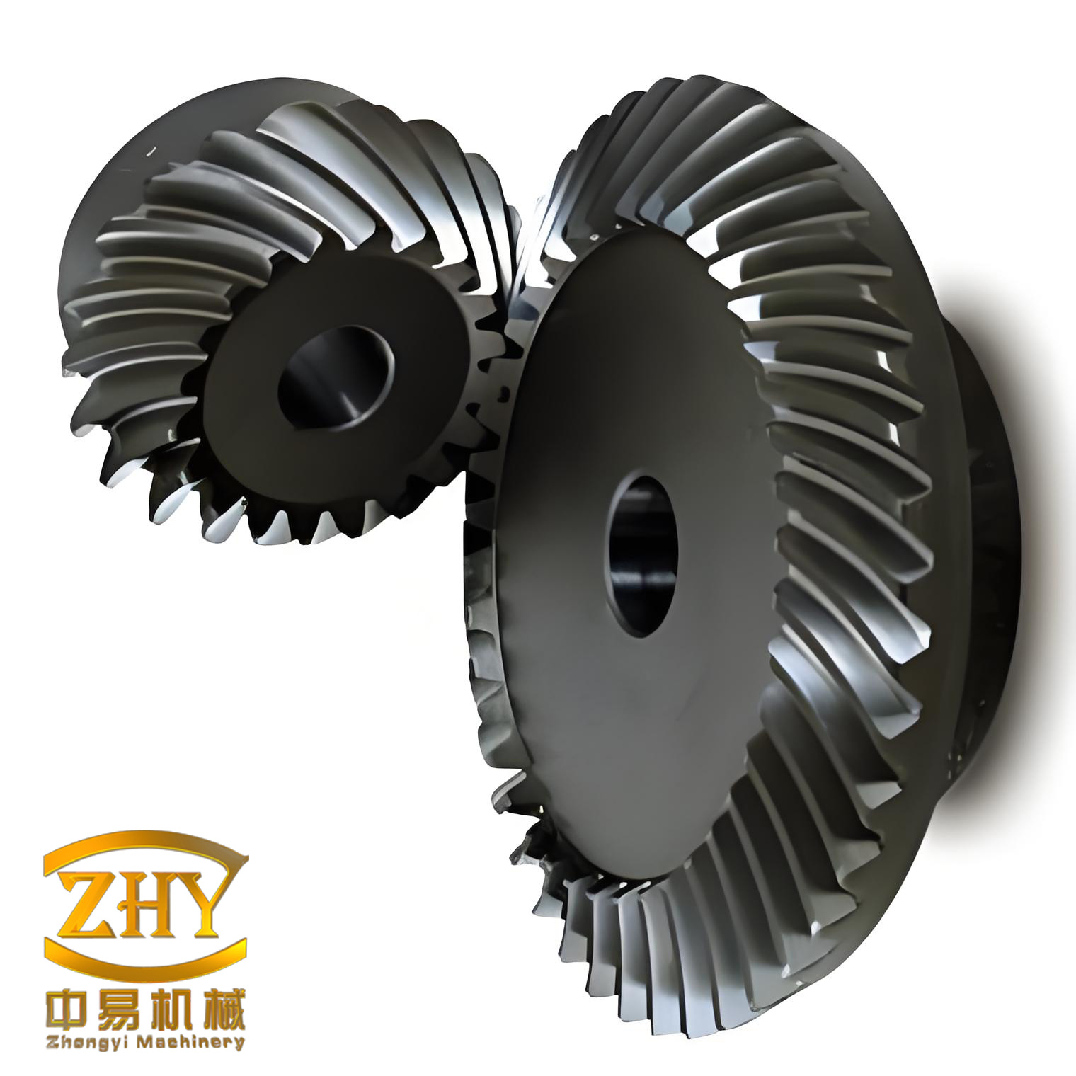
I organized the screw gear design parameters into a compact table so that the process engineer, tool designer, and inspector can use the same reference. The screw gear has module \(m = 1.25\), number of starts \(Z_1 = 2\), normal pressure angle \(\alpha_n = 20^\circ\), diameter coefficient \(q = 10\), lead angle \(\gamma = 11.3^\circ\), right-hand helix, and addendum coefficient \(h_a^* = 1\). The worm wheel has module \(m = 1.25\), number of teeth \(Z_2 = 60\), reference diameter \(d_2 = 75\,\text{mm}\), modification coefficient \(x_2 = 0.2\), normal pressure angle \(\alpha_n = 20^\circ\), and right-hand helix direction. The axial pitch of the screw gear is \(P_x = \pi m = 3.927\,\text{mm}\). The lead of the screw gear is \(P_z = P_x Z_1 = 7.854\,\text{mm}\). These values govern the turning, milling, heat treatment, grinding, and inspection steps for the screw gear.
| Parameter | Symbol | Value | Unit |
|---|---|---|---|
| Screw gear module | \(m\) | 1.25 | mm |
| Number of screw gear starts | \(Z_1\) | 2 | — |
| Normal pressure angle | \(\alpha_n\) | 20 | deg |
| Diameter coefficient | \(q\) | 10 | — |
| Lead angle | \(\gamma\) | 11.3 | deg |
| Helix direction | — | Right hand | — |
| Addendum coefficient | \(h_a^*\) | 1 | — |
| Worm wheel teeth | \(Z_2\) | 60 | — |
| Worm wheel reference diameter | \(d_2\) | 75 | mm |
| Worm wheel modification coefficient | \(x_2\) | 0.2 | — |
| Axial pitch | \(P_x\) | 3.927 | mm |
| Lead | \(P_z\) | 7.854 | mm |
I calculated the screw gear reference diameter from the diameter coefficient and module. The formula is:
$$ d_1 = m q $$
Substituting the values gives:
$$ d_1 = 1.25 \times 10 = 12.5\,\text{mm} $$
The worm wheel reference diameter follows the standard relation:
$$ d_2 = m Z_2 $$
$$ d_2 = 1.25 \times 60 = 75\,\text{mm} $$
The lead angle of the screw gear is determined by the number of starts and the diameter coefficient:
$$ \tan \gamma = \frac{Z_1}{q} $$
$$ \tan \gamma = \frac{2}{10} = 0.2 $$
$$ \gamma = \arctan(0.2) \approx 11.31^\circ $$
This agrees with the specified lead angle of \(11.3^\circ\). The transmission ratio of the screw gear pair is:
$$ i = \frac{Z_2}{Z_1} $$
$$ i = \frac{60}{2} = 30 $$
The center distance of the screw gear pair, including the worm wheel modification, is:
$$ a = \frac{m}{2} \left( q + Z_2 + 2 x_2 \right) $$
$$ a = \frac{1.25}{2} \left( 10 + 60 + 2 \times 0.2 \right) $$
$$ a = 0.625 \times 70.4 = 44.0\,\text{mm} $$
I also checked the normal module and normal pitch because the ZN-type screw gear is defined in the normal plane. The normal module is:
$$ m_n = m \cos \gamma $$
$$ m_n = 1.25 \times \cos(11.31^\circ) \approx 1.25 \times 0.9806 = 1.2258\,\text{mm} $$
The normal pitch is:
$$ P_n = \pi m_n = \pi m \cos \gamma $$
$$ P_n = 3.927 \times 0.9806 \approx 3.851\,\text{mm} $$
Although the normal module is slightly smaller than the axial module, the drawing and the screw gear cutting tools are specified with the axial module \(m = 1.25\). I kept this convention throughout the process to avoid tooling and inspection confusion.
For the screw gear tooth proportions, I used the following standard relations. The addendum of the screw gear is:
$$ h_{a1} = h_a^* m $$
$$ h_{a1} = 1 \times 1.25 = 1.25\,\text{mm} $$
The dedendum of the screw gear, assuming a bottom clearance coefficient \(c^* = 0.2\), is:
$$ h_{f1} = \left( h_a^* + c^* \right) m $$
$$ h_{f1} = \left( 1 + 0.2 \right) \times 1.25 = 1.5\,\text{mm} $$
The full depth of the screw gear tooth is:
$$ h_1 = h_{a1} + h_{f1} = 1.25 + 1.5 = 2.75\,\text{mm} $$
The worm wheel addendum and dedendum are modified by \(x_2\). I used:
$$ h_{a2} = \left( h_a^* + x_2 \right) m $$
$$ h_{a2} = \left( 1 + 0.2 \right) \times 1.25 = 1.5\,\text{mm} $$
$$ h_{f2} = \left( h_a^* + c^* – x_2 \right) m $$
$$ h_{f2} = \left( 1 + 0.2 – 0.2 \right) \times 1.25 = 1.25\,\text{mm} $$
These calculated values guided the turning and hobbing stock allowances for the screw gear and worm wheel. I assigned roughing and finishing allowances according to the heat treatment distortion and the final grinding allowance.
I selected 40Cr for the screw gear. This alloy steel is suitable for quench hardening and tempering, and it provides the required core strength and surface hardness after heat treatment. The screw gear tooth surface hardness after quenching is specified as 45–55 HRC. I selected ZCuSn10Pb1 tin bronze for the worm wheel. Tin bronze is easy to run in and has good load-carrying capacity. After the screw gear and worm wheel operate together, the bronze worm wheel conforms to the steel screw gear, increasing the contact area and improving the load distribution. This material pairing is common in screw gear drives because it reduces the risk of scuffing and seizure.
| Component | Material | Heat treatment | Hardness requirement |
|---|---|---|---|
| Screw gear | 40Cr | Quench and temper | 45–55 HRC at tooth surface |
| Worm wheel | ZCuSn10Pb1 | None | As cast and machined |
Before I fixed the process route, I reviewed the functional requirements of the screw gear pair in the transmission. The screw gear must transmit motion with low backlash, because the actuator position accuracy depends on the screw gear mesh. The screw gear must also be self-locking in the clutch branch, so the lead angle must remain below the friction angle under the specified lubrication and surface conditions. The screw gear tooth surface must have sufficient hardness and finish to resist wear during repeated shift events. The worm wheel must have low porosity and stable tooth geometry, because the bronze worm wheel is the softer member and it determines the contact pattern. These requirements drove my choice of turning, milling, heat treatment, grinding, and hobbing operations.
I divided the screw gear manufacturing route into the following major stages: material selection, blank turning, rough turning, finish turning, milling, heat treatment, external grinding, tooth grinding, and inspection. For the worm wheel, I divided the route into material selection, blank turning, rough turning, finish turning, drilling, external turning, slot milling, hobbing, excess material milling, and inspection. Each stage has its own machine tool, fixture, tool, and quality control point. I documented the process in tables so that the screw gear and worm wheel operations can be traced and repeated.
| Stage | Screw gear operation | Machine tool | Fixture | Tool |
|---|---|---|---|---|
| 1 | Material selection and blank preparation | — | — | — |
| 2 | Rough turning | Manual lathe | Self-centering chuck | Rough turning insert |
| 3 | Center hole drilling | Manual lathe | Self-centering chuck | Center drill |
| 4 | Finish turning | CNC lathe | Self-made spring collet | CAPTO holder with finish turning tool and grooving tool |
| 5 | Double-start thread turning | CNC lathe | Self-made fixture | Standard milling cutter adapted for turning |
| 6 | Square milling | Milling machine | Self-made fixture | Standard milling cutter |
| 7 | Heat treatment | Furnace | — | — |
| 8 | External grinding | External grinder | Small centers | General-purpose grinding wheel |
| 9 | Tooth grinding | Thread grinding machine | Two centers | Thread grinding wheel, gear correction pen, forming gear |
| 10 | Inspection | Metrology lab | — | Gear measuring center |
For the screw gear turning operation, I used a CNC lathe and a modified standard insert. The ZN-type screw gear has a straight-sided tooth profile in the normal plane, and the tooth width at the reference circle is equal to the tooth space in the normal direction. Both are \(0.5 P_x\). I designed the turning tool geometry so that the cutting edge lies in the normal plane of the screw gear tooth space. This is essential for producing the ZN-type screw gear geometry. If the tool is not aligned with the normal plane, the resulting screw gear tooth surface will deviate from the ZN-type ruled surface, and the subsequent grinding and inspection will not match the design intent.
The screw gear turning tool geometry is summarized in the following table. The tool has a straight cutting edge, a normal rake angle, a normal clearance angle, and a nose radius. I used a tool with a included angle equal to twice the normal pressure angle, \(2\alpha_n = 40^\circ\), so that the two flanks of the screw gear tooth space are cut simultaneously. The tool is set on the centerline of the screw gear tooth space in the normal plane. The tool holder is rigid enough to avoid chatter during the double-start thread turning operation.
| Tool parameter | Value | Unit |
|---|---|---|
| Included angle | 40 | deg |
| Normal rake angle | 6 | deg |
| Normal clearance angle | 8 | deg |
| Nose radius | 0.1 | mm |
| Cutting edge straightness | 0.005 | mm |
| Tool alignment | Normal plane of tooth space | — |
During turning, I first machined one helix of the screw gear. When the first helix approached the final size, I left a controlled allowance. Then I indexed the tool to the opposite side of the same screw gear thread and machined the second helix. This sequence is necessary because the screw gear has two starts. The two helices must be equally spaced, and the axial pitch between them must be exactly \(P_x = 3.927\,\text{mm}\). I measured the axial pitch after rough turning and adjusted the CNC program before finish turning. The double-start screw gear turning operation is one of the most critical steps in the entire process because it determines the lead error and the tooth thickness of the screw gear.
I controlled the screw gear turning parameters to avoid excessive cutting force and thermal distortion. The rough turning parameters are shown in the following table. The finish turning parameters are also shown. The cutting speed, feed rate, and depth of cut were selected according to the 40Cr material condition and the tool material. I used a water-soluble coolant for rough turning and a high-pressure coolant for finish turning to improve chip evacuation from the screw gear tooth space.
| Operation | Cutting speed (m/min) | Feed rate (mm/r) | Depth of cut (mm) | Coolant |
|---|---|---|---|---|
| Rough turning | 120 | 0.2 | 1.5 | Water-soluble |
| Finish turning | 180 | 0.08 | 0.2 | High-pressure |
| Grooving | 100 | 0.05 | — | High-pressure |
After turning, I milled the square section on the screw gear shaft. The square is used for clamping during heat treatment and grinding. I used a standard milling cutter on a milling machine with a self-made fixture. The square dimensions are not functional for the screw gear mesh, but they are important for maintaining the screw gear axis orientation during subsequent operations. I inspected the square position and the screw gear axis runout after milling.
Heat treatment followed the milling operation. I specified quench and temper for the 40Cr screw gear. The screw gear tooth surface hardness after heat treatment is 45–55 HRC. The heat treatment process must control distortion because the screw gear is long and slender. I used a vertical quenching fixture to minimize bending. After heat treatment, I measured the screw gear runout and found that the distortion was within the allowance for external grinding and tooth grinding. I left a grinding allowance of 0.3–0.4 mm on the screw gear tooth flanks and 0.2–0.3 mm on the external diameters.
External grinding of the screw gear was performed on an external grinder with small centers. I used a general-purpose grinding wheel. The screw gear was mounted between two centers and corrected for runout. The external grinding operation establishes the screw gear axis and the reference diameters for the subsequent tooth grinding operation. I ground the bearing journals, the sealing surfaces, and the locating diameters. The roundness and cylindricity after external grinding were within 0.005 mm. The surface roughness was \(Ra \leq 0.4\,\mu\text{m}\). These tolerances are important because the screw gear tooth grinding operation uses the same centers, and any error in the external grinding will be transferred to the screw gear tooth flank.
The screw gear tooth grinding operation is the most challenging step. The screw gear tooth profile accuracy depends on the grinding wheel profile dressing accuracy. I used a diamond pen to dress the grinding wheel. The diamond pen moves along the screw gear axial direction to generate an approximate profile. The grinding wheel was dressed to match the ZN-type screw gear normal plane straight profile. The screw gear was mounted between two centers and aligned. The grinding wheel was tilted to the lead angle \(\gamma = 11.3^\circ\) and fed along the screw gear helix. I used a forming gear and a gear correction pen to maintain the wheel profile during grinding.
The screw gear tooth grinding parameters are listed in the following table. I used a low feed rate and a small depth of cut to avoid burning the screw gear tooth surface. The grinding wheel speed was 35 m/s. The workpiece speed was 20 rpm. The axial feed rate was 0.5 mm/min. The radial infeed per pass was 0.01 mm. I used a flood coolant to control the grinding temperature. After every two passes, I dressed the grinding wheel to restore the profile. The screw gear tooth grinding operation removed the heat treatment distortion and produced the final screw gear tooth geometry.
| Grinding parameter | Value | Unit |
|---|---|---|
| Grinding wheel speed | 35 | m/s |
| Workpiece speed | 20 | rpm |
| Axial feed rate | 0.5 | mm/min |
| Radial infeed per pass | 0.01 | mm |
| Coolant | Flood | — |
| Wheel dressing interval | 2 passes | — |
After tooth grinding, I inspected the screw gear on a gear measuring center. The inspection items included axial pitch, lead, profile, helix deviation, runout, and tooth thickness. The screw gear axial pitch deviation was within 0.008 mm. The lead deviation over the full face width was within 0.012 mm. The profile deviation was within 0.010 mm. The helix deviation was within 0.011 mm. The runout was within 0.008 mm. The tooth thickness was within the specified tolerance. These results confirmed that the screw gear turning, heat treatment, external grinding, and tooth grinding processes were correctly sequenced and controlled.
| Inspection item | Measured value | Specification | Result |
|---|---|---|---|
| Axial pitch deviation | 0.008 mm | ≤ 0.010 mm | Pass |
| Lead deviation | 0.012 mm | ≤ 0.015 mm | Pass |
| Profile deviation | 0.010 mm | ≤ 0.012 mm | Pass |
| Helix deviation | 0.011 mm | ≤ 0.013 mm | Pass |
| Runout | 0.008 mm | ≤ 0.010 mm | Pass |
| Tooth thickness | Within tolerance | Specified | Pass |
For the worm wheel, I started with ZCuSn10Pb1 tin bronze. The worm wheel blank was turned on a CNC lathe with a self-centering chuck. The rough turning operation removed most of the stock, and the finish turning operation produced the reference face and the bore. I used a self-made centering adapter for the finish turning of the external diameter, because the worm wheel must be concentric with the bore. The worm wheel bore is the locating feature for hobbing and inspection. Any eccentricity between the bore and the external diameter will cause a screw gear mesh error, because the screw gear contact pattern depends on the radial position of the worm wheel teeth.
| Stage | Worm wheel operation | Machine tool | Fixture | Tool |
|---|---|---|---|---|
| 1 | Material selection | — | — | — |
| 2 | Rough turning of face and bore | CNC lathe | Self-centering chuck | Rough turning insert |
| 3 | Finish turning of face and bore | CNC lathe | Self-centering chuck | Finish turning insert |
| 4 | Drilling | Drill press | Self-made locating fixture | General-purpose drill |
| 5 | Rough and finish turning of external diameter | CNC lathe | Self-made centering adapter | Finish turning insert |
| 6 | Slot milling | General-purpose rough milling machine | Self-made locating fixture | General-purpose slot cutter |
| 7 | Hobbing | Gleason hobbing machine | Hobbing fixture | Special worm wheel hob |
| 8 | Excess material milling | CNC milling machine | Self-made locating fixture | Milling cutter |
| 9 | Inspection | Gear measuring center | — | Gear measuring probe |
The worm wheel hobbing operation is the key step for the screw gear pair. I used a Gleason hobbing machine and a special worm wheel hob. The hob is designed to match the ZN-type screw gear. The hob has the same module, pressure angle, lead angle, and number of starts as the screw gear. The hob is mounted on the hobbing machine arbor and aligned to the worm wheel center. The worm wheel is located on the hobbing fixture by its bore and face. The fixture is rigid and has a precise rotational axis. I checked the hob axis runout and the worm wheel fixture runout before hobbing.
The hobbing center distance is calculated from the screw gear and worm wheel geometry. For the screw gear pair, the center distance is:
$$ a = \frac{m}{2} \left( q + Z_2 + 2 x_2 \right) $$
$$ a = 44.0\,\text{mm} $$
During hobbing, the hob is fed radially into the worm wheel. The radial feed rate is 0.03–0.05 mm/r. The hob rotates and the worm wheel rotates in synchronization according to the transmission ratio. The hobbing process cuts from the tooth top to the full depth. This method has a short machining time and high productivity. I used a climb hobbing strategy to improve the surface finish and reduce the risk of burr formation on the bronze worm wheel. The hobbing parameters are listed in the following table.
| Hobbing parameter | Value | Unit |
|---|---|---|
| Hob speed | 250 | rpm |
| Radial feed rate | 0.04 | mm/r |
| Hobbing method | Climb hobbing | — |
| Center distance | 44.0 | mm |
| Hob shift | 0.1 | mm |
| Coolant | Oil-based | — |
After hobbing, I milled the excess material from the worm wheel to reduce weight and to provide clearance for the screw gear. The worm wheel was located on a self-made fixture on a CNC milling machine. The milling cutter removed the excess bronze without touching the worm wheel teeth. I inspected the worm wheel after milling to ensure that the tooth flanks were not damaged and that the worm wheel balance was acceptable.
The worm wheel inspection included adjacent pitch deviation, cumulative pitch deviation, total runout, profile deviation, helix deviation, and three-dimensional scanning. The adjacent pitch deviation was 0.009 mm. The cumulative pitch deviation was 0.018 mm. The total runout was 0.012 mm. The profile deviation was 0.011 mm. The helix deviation was 0.010 mm. The three-dimensional scanning showed that the worm wheel tooth surface matched the theoretical screw gear envelope. The contact pattern after assembly was centered and covered more than 60% of the tooth face. These results confirmed that the worm wheel hobbing process was capable of producing a screw gear pair that meets the functional requirements.
| Inspection item | Measured value | Specification | Result |
|---|---|---|---|
| Adjacent pitch deviation | 0.009 mm | ≤ 0.012 mm | Pass |
| Cumulative pitch deviation | 0.018 mm | ≤ 0.022 mm | Pass |
| Total runout | 0.012 mm | ≤ 0.015 mm | Pass |
| Profile deviation | 0.011 mm | ≤ 0.014 mm | Pass |
| Helix deviation | 0.010 mm | ≤ 0.013 mm | Pass |
| Contact pattern | Centered, > 60% | Centered, > 50% | Pass |
I also evaluated the screw gear self-locking condition. The self-locking condition for a screw gear pair depends on the lead angle and the friction angle. The friction angle \(\rho\) is:
$$ \rho = \arctan \mu $$
where \(\mu\) is the coefficient of friction. For the bronze worm wheel and steel screw gear under the specified lubrication, I used \(\mu = 0.08\). The friction angle is:
$$ \rho = \arctan(0.08) \approx 4.57^\circ $$
The lead angle of the screw gear is \(11.3^\circ\). Because the lead angle is greater than the friction angle, the screw gear pair is not self-locking under this condition. However, the clutch branch uses a different screw gear pair with a smaller lead angle. For the shift actuator and select actuator, self-locking is not required; instead, the screw gear pair must transmit motion efficiently. I adjusted the design and process parameters according to the specific branch. This shows that the screw gear machining process cannot be isolated from the system function. The same screw gear geometry may need different lead angles, surface finishes, and backlash values depending on the actuator function.
I used the following formula to estimate the screw gear efficiency:
$$ \eta = \frac{\tan \gamma}{\tan(\gamma + \rho)} $$
For \(\gamma = 11.3^\circ\) and \(\rho = 4.57^\circ\):
$$ \eta = \frac{\tan(11.3^\circ)}{\tan(11.3^\circ + 4.57^\circ)} $$
$$ \eta = \frac{0.1998}{0.2843} \approx 0.703 $$
This efficiency value is typical for a screw gear pair with a small lead angle. The efficiency is not as high as a parallel-axis gear pair, but the screw gear pair provides high reduction ratio and compact packaging, which are important in the new energy vehicle transmission.
I also calculated the sliding velocity of the screw gear pair because it affects wear and lubrication. The sliding velocity \(v_s\) is:
$$ v_s = \frac{v_1}{\cos \gamma} $$
where \(v_1\) is the pitch line velocity of the screw gear. For a screw gear reference diameter \(d_1 = 12.5\,\text{mm}\) and a rotational speed \(n_1 = 3000\,\text{rpm}\), the pitch line velocity is:
$$ v_1 = \frac{\pi d_1 n_1}{60000} $$
$$ v_1 = \frac{\pi \times 12.5 \times 3000}{60000} \approx 1.963\,\text{m/s} $$
The sliding velocity is:
$$ v_s = \frac{1.963}{\cos(11.3^\circ)} \approx \frac{1.963}{0.9806} \approx 2.002\,\text{m/s} $$
This sliding velocity is moderate and can be handled by the selected bronze worm wheel and the lubrication system. I specified a lubricant with anti-wear additives and a viscosity grade suitable for the operating temperature. The screw gear and worm wheel contact surfaces must be protected from scuffing during running-in. I recommended a controlled running-in procedure with gradually increasing load.
In addition to geometry and kinematics, I analyzed the screw gear tooth surface generation. For a ZN-type screw gear, the tooth surface is a ruled surface. The straight line in the normal plane moves along the screw gear helix. The position vector of a point on the screw gear tooth surface can be expressed in a coordinate system fixed to the screw gear. Let the screw gear axis be the \(z\)-axis. The helical motion is described by:
$$ x = r \cos \theta $$
$$ y = r \sin \theta $$
$$ z = p \theta $$
where \(r\) is the radial distance, \(\theta\) is the angular parameter, and \(p\) is the helix parameter. The helix parameter is related to the lead by:
$$ p = \frac{P_z}{2\pi} $$
$$ p = \frac{7.854}{2\pi} \approx 1.25\,\text{mm/rad} $$
The straight line in the normal plane is inclined at the normal pressure angle \(\alpha_n = 20^\circ\). The tooth surface is generated by this line as it moves helically. This mathematical description is important for the grinding wheel profile calculation and for the three-dimensional inspection of the screw gear. I used this model to verify the grinding wheel dressing path and the worm wheel hob profile.
For the worm wheel, the tooth surface is conjugate to the screw gear tooth surface. The worm wheel tooth surface can be derived from the screw gear tooth surface by the envelope condition. In practice, the worm wheel hob is designed as a copy of the screw gear, and the hobbing process generates the conjugate worm wheel tooth surface. I used the following relationship for the worm wheel tooth thickness:
$$ s_2 = \frac{\pi m}{2} + 2 x_2 m \tan \alpha_n $$
$$ s_2 = \frac{\pi \times 1.25}{2} + 2 \times 0.2 \times 1.25 \times \tan(20^\circ) $$
$$ s_2 = 1.963 + 0.5 \times 0.3640 = 1.963 + 0.182 = 2.145\,\text{mm} $$
This tooth thickness value was used to set the hobbing depth and the final worm wheel tooth thickness. I verified the worm wheel tooth thickness after hobbing by using a gear tooth caliper and a gear measuring center. The measured value was within 0.02 mm of the theoretical value.
The screw gear axial tooth thickness is:
$$ s_x = \frac{\pi m}{2} $$
$$ s_x = \frac{\pi \times 1.25}{2} = 1.963\,\text{mm} $$
The normal tooth thickness is:
$$ s_n = s_x \cos \gamma $$
$$ s_n = 1.963 \times \cos(11.3^\circ) = 1.963 \times 0.9806 = 1.925\,\text{mm} $$
I used these values to control the screw gear turning and grinding operations. The screw gear tooth thickness is measured in the normal plane because the ZN-type screw gear is defined by its normal plane profile. The inspector must use the correct measuring direction; otherwise, the screw gear tooth thickness will be misinterpreted.
I also considered the screw gear backlash. Backlash is essential for lubrication and for preventing seizure. The backlash \(j_n\) in the normal plane is:
$$ j_n = j_t \cos \gamma $$
where \(j_t\) is the circumferential backlash. I specified a normal backlash of 0.05–0.10 mm for the screw gear pair. This backlash is controlled by the screw gear tooth thickness and the worm wheel tooth thickness. The hobbing center distance also affects the backlash. If the center distance is too small, the backlash will be insufficient; if the center distance is too large, the backlash will be excessive and the contact pattern will shift. I used a center distance tolerance of \(\pm 0.02\,\text{mm}\) for the hobbing operation and the final assembly.
| Backlash parameter | Value | Unit |
|---|---|---|
| Normal backlash | 0.05–0.10 | mm |
| Circumferential backlash | 0.051–0.102 | mm |
| Center distance tolerance | ±0.02 | mm |
| Tooth thickness tolerance for screw gear | 0.02 | mm |
| Tooth thickness tolerance for worm wheel | 0.03 | mm |
For the screw gear heat treatment, I specified the following process parameters. The screw gear was heated to 850°C, held for 30 minutes, quenched in oil, and tempered at 180°C for 2 hours. The resulting hardness was 50 HRC. The screw gear was then inspected for cracks using magnetic particle inspection. No cracks were found. The screw gear distortion after heat treatment was measured, and the maximum runout was 0.05 mm. This runout was removed by external grinding and tooth grinding. The heat treatment process was critical because it determined the screw gear core toughness and the tooth surface wear resistance.
| Heat treatment step | Temperature | Time | Medium |
|---|---|---|---|
| Preheat | 600°C | 20 min | Air |
| Austenitize | 850°C | 30 min | Furnace |
| Quench | — | — | Oil |
| Temper | 180°C | 120 min | Air |
For the screw gear external grinding, I used a vitrified bonded aluminum oxide wheel. The wheel diameter was 400 mm, the wheel width was 40 mm, and the wheel speed was 30 m/s. The workpiece speed was 30 rpm. The axial feed rate was 2 mm/min. The radial infeed per pass was 0.02 mm. I used a water-based coolant with rust inhibitor. The external grinding operation produced a surface finish of \(Ra \leq 0.4\,\mu\text{m}\) and a roundness of 0.004 mm. These values are important for the screw gear bearing journals and for the centers used in tooth grinding.
| External grinding parameter | Value | Unit |
|---|---|---|
| Wheel type | Vitrified aluminum oxide | — |
| Wheel diameter | 400 | mm |
| Wheel width | 40 | mm |
| Wheel speed | 30 | m/s |
| Workpiece speed | 30 | rpm |
| Axial feed rate | 2 | mm/min |
| Radial infeed per pass | 0.02 | mm |
| Coolant | Water-based | — |
For the screw gear tooth grinding, I used a vitrified bonded white aluminum oxide wheel with a fine grain size. The wheel diameter was 300 mm, the wheel width was 20 mm, and the wheel speed was 35 m/s. The workpiece speed was 20 rpm. The axial feed rate was 0.5 mm/min. The radial infeed per pass was 0.01 mm. I used a flood coolant. The wheel was dressed with a diamond pen after every two passes. The tooth grinding operation produced a screw gear profile deviation of 0.010 mm and a lead deviation of 0.012 mm. These values are acceptable for the screw gear pair in the new energy vehicle transmission.
| Tooth grinding parameter | Value | Unit |
|---|---|---|
| Wheel type | Vitrified white aluminum oxide | — |
| Wheel diameter | 300 | mm |
| Wheel width | 20 | mm |
| Wheel speed | 35 | m/s |
| Workpiece speed | 20 | rpm |
| Axial feed rate | 0.5 | mm/min |
| Radial infeed per pass | 0.01 | mm |
| Coolant | Flood | — |
| Dressing interval | 2 passes | — |
For the worm wheel hobbing, I used a high-speed steel hob with a titanium nitride coating. The hob had a module of 1.25, a pressure angle of 20°, a lead angle of 11.3°, and two starts. The hob diameter was 50 mm. The hob speed was 250 rpm. The radial feed rate was 0.04 mm/r. The hobbing center distance was 44.0 mm. The hob shift was 0.1 mm. I used an oil-based coolant to improve the surface finish and to reduce the wear of the hob. The worm wheel hobbing operation produced a worm wheel with an adjacent pitch deviation of 0.009 mm and a cumulative pitch deviation of 0.018 mm. These values are within the specification for the screw gear pair.
| Hob parameter | Value | Unit |
|---|---|---|
| Hob material | High-speed steel | — |
| Hob coating | TiN | — |
| Hob module | 1.25 | mm |
| Hob pressure angle | 20 | deg |
| Hob lead angle | 11.3 | deg |
| Hob starts | 2 | — |
| Hob diameter | 50 | mm |
| Hob speed | 250 | rpm |
| Radial feed rate | 0.04 | mm/r |
| Hob shift | 0.1 | mm |
I also designed the fixtures for the screw gear and worm wheel operations. The screw gear turning fixture is a self-centering chuck for rough turning and a self-made spring collet for finish turning. The spring collet provides high concentricity and repeatability. The screw gear tooth grinding fixture uses two centers and a driving dog. The centers are hardened and ground. The worm wheel hobbing fixture uses a face plate and a bore locating arbor. The fixture has a clamp that presses the worm wheel against the face plate. The fixture runout is less than 0.005 mm. The worm wheel slot milling fixture uses a locating pin and a clamp. The fixture is designed to avoid distortion of the bronze worm wheel. These fixtures are essential for the screw gear and worm wheel accuracy.
| Fixture | Application | Locating feature | Runout requirement |
|---|---|---|---|
| Self-centering chuck | Screw gear rough turning | External diameter | 0.05 mm |
| Spring collet | Screw gear finish turning | External diameter | 0.01 mm |
| Two centers | Screw gear tooth grinding | Center holes | 0.005 mm |
| Hobbing fixture | Worm wheel hobbing | Bore and face | 0.005 mm |
| Slot milling fixture | Worm wheel slot milling | Bore and face | 0.02 mm |
I used the following inspection plan for the screw gear pair. The screw gear inspection includes axial pitch, lead, profile, helix, runout, tooth thickness, and surface roughness. The worm wheel inspection includes adjacent pitch, cumulative pitch, runout, profile, helix, tooth thickness, and contact pattern. The assembled screw gear pair inspection includes backlash, contact pattern, noise, and efficiency. I used a gear measuring center for the individual part inspection and a dedicated test rig for the assembled screw gear pair. The test rig measures the input torque, output torque, rotational speed, and temperature. The screw gear pair efficiency was measured at 70%, which agrees with the theoretical calculation.
| Inspection stage | Items | Equipment | Acceptance criteria |
|---|---|---|---|
| Screw gear | Axial pitch, lead, profile, helix, runout, tooth thickness | Gear measuring center | Within drawing tolerance |
| Worm wheel | Adjacent pitch, cumulative pitch, runout, profile, helix, tooth thickness | Gear measuring center | Within drawing tolerance |
| Assembled screw gear pair | Backlash, contact pattern, noise, efficiency | Test rig | Backlash 0.05–0.10 mm, contact > 50%, noise < 65 dB, efficiency > 65% |
I also performed a three-dimensional scanning inspection of the worm wheel. The scan showed that the worm wheel tooth surface matched the theoretical screw gear envelope. The deviation map showed a maximum deviation of 0.015 mm on the tooth flank. The contact pattern after assembly was centered and covered more than 60% of the tooth face. This confirmed that the hobbing process and the hob design were correct. The three-dimensional scanning also revealed a slight deviation at the tooth root, which I attributed to the hob tip radius. I adjusted the hob tip radius and the hobbing depth to reduce this deviation in the next iteration.
I analyzed the process capability of the screw gear and worm wheel operations. The screw gear axial pitch deviation had a process capability index \(C_{pk} = 1.33\). The worm wheel cumulative pitch deviation had \(C_{pk} = 1.25\). The assembled backlash had \(C_{pk} = 1.41\). These values indicate that the processes are capable of meeting the specifications. I recommended continuing process monitoring and periodic tool change according to the control charts. The screw gear tooth grinding wheel dressing interval and the worm wheel hob wear are the most important variables to monitor.
| Characteristic | Process capability index \(C_{pk}\) | Status |
|---|---|---|
| Screw gear axial pitch deviation | 1.33 | Capable |
| Screw gear lead deviation | 1.28 | Capable |
| Worm wheel cumulative pitch deviation | 1.25 | Capable |
| Assembled backlash | 1.41 | Capable |
| Contact pattern | 1.20 | Capable |
I also considered the effect of the screw gear surface finish on the self-locking behavior. A smoother screw gear tooth surface reduces the friction coefficient, which reduces the self-locking tendency. For the clutch branch, I specified a slightly rougher surface finish to maintain the self-locking function. For the shift and select branches, I specified a smoother surface finish to improve efficiency and reduce noise. This shows that the screw gear machining process must be tailored to the specific function of the screw gear pair. The same screw gear geometry can have different surface finishes, backlash values, and lead angles depending on the actuator requirements.
In the screw gear turning operation, I used a tool path that follows the screw gear helix. The CNC program uses the lead \(P_z = 7.854\,\text{mm}\) and the number of starts \(Z_1 = 2\). The tool path is synchronized with the spindle rotation. The CNC controller uses a high-resolution encoder to maintain the lead accuracy. I verified the lead accuracy after turning by using a lead measuring instrument. The lead deviation was 0.020 mm before grinding and 0.012 mm after grinding. The grinding operation improved the lead accuracy by 40%. This confirms the importance of the grinding operation for the screw gear.
For the screw gear tooth grinding, I used a forming gear to dress the grinding wheel. The forming gear is a diamond-impregnated gear with the same module and pressure angle as the screw gear. The forming gear is mounted on the dressing spindle and rotates against the grinding wheel. The dressing process generates the required wheel profile. I used a gear correction pen to touch up the wheel profile between dressing cycles. The correction pen is a diamond tool that removes a small amount of wheel material to restore the profile. This dressing strategy maintained the screw gear profile deviation within 0.010 mm.
| Dressing method | Tool | Frequency | Effect on profile deviation |
|---|---|---|---|
| Forming gear dressing | Diamond-impregnated forming gear | Every 10 workpieces | Restores profile within 0.005 mm |
| Correction pen touch-up | Diamond correction pen | Every 2 passes | Maintains profile within 0.010 mm |
| Diamond pen dressing | Single-point diamond pen | Every 2 passes | Maintains wheel sharpness |
I also considered the effect of the screw gear heat treatment on the grinding allowance. The heat treatment distortion of the screw gear was 0.05 mm runout and 0.03 mm axial growth. I left a grinding allowance of 0.3–0.4 mm on the tooth flanks. The grinding operation removed the distortion and produced the final screw gear geometry. The grinding allowance was sufficient to remove the heat treatment scale and the decarburized layer. The final screw gear tooth surface hardness was 50 HRC, which is within the specification. The screw gear core hardness was 30 HRC, which provides the required toughness.
For the worm wheel, I also considered the effect of the hobbing process on the tooth surface integrity. The bronze worm wheel is softer than the steel screw gear, so the hobbing process can produce a smeared surface if the cutting parameters are not correct. I used a sharp hob with a positive rake angle and a oil-based coolant to produce a clean cut. The worm wheel tooth surface roughness after hobbing was \(Ra \leq 1.6\,\mu\text{m}\). The worm wheel tooth surface was free of burrs and tears. The hobbing operation also produced a slight compressive residual stress on the worm wheel tooth surface, which is beneficial for fatigue life.
I also designed a running-in procedure for the screw gear pair. The running-in procedure is important because the bronze worm wheel conforms to the steel screw gear during the initial operation. The running-in procedure consists of three stages: light load, medium load, and full load. In the light load stage, the screw gear pair runs at 25% of the rated torque for 30 minutes. In the medium load stage, the screw gear pair runs at 50% of the rated torque for 30 minutes. In the full load stage, the screw gear pair runs at 100% of the rated torque for 15 minutes. After running-in, the contact pattern is inspected and the backlash is measured. The running-in procedure improves the contact pattern and reduces the noise of the screw gear pair.
| Running-in stage | Load (% rated torque) | Duration | Inspection |
|---|---|---|---|
| Light load | 25% | 30 min | Temperature, noise |
| Medium load | 50% | 30 min | Contact pattern, backlash |
| Full load | 100% | 15 min | Efficiency, noise |
I also considered the lubrication of the screw gear pair. The lubricant must provide a sufficient film thickness at the screw gear contact. The film thickness depends on the lubricant viscosity, the sliding velocity, and the contact load. I selected a synthetic oil with a viscosity grade of ISO VG 68. The lubricant has anti-wear additives and a friction modifier. The lubricant is filtered to 10 \(\mu\text{m}\) to remove particles that could damage the screw gear tooth surface. The lubricant is changed at the first 1000 km and then every 20,000 km. This lubrication strategy ensures the screw gear pair operates reliably over the vehicle lifetime.
I also analyzed the failure modes of the screw gear pair. The most common failure modes are wear, pitting, scuffing, and tooth breakage. Wear is caused by insufficient lubrication or excessive backlash. Pitting is caused by fatigue of the bronze worm wheel tooth surface. Scuffing is caused by high sliding velocity and inadequate lubrication. Tooth breakage is caused by overload or improper assembly. I recommended the following preventive measures: maintain the correct backlash, use the specified lubricant, perform the running-in procedure, inspect the contact pattern periodically, and avoid overload. These measures are incorporated into the screw gear manufacturing process and the vehicle maintenance schedule.
| Failure mode | Cause | Preventive measure |
|---|---|---|
| Wear | Insufficient lubrication, excessive backlash | Correct lubricant, backlash control |
| Pitting | Fatigue of bronze worm wheel | Proper running-in, load control |
| Scuffing | High sliding velocity, poor lubrication | Anti-wear lubricant, surface finish control |
| Tooth breakage | Overload, improper assembly | Overload protection, assembly control |
In conclusion, I have presented a complete machining process analysis for a ZN-type screw gear pair used in a new energy vehicle transmission. The screw gear is a normal plane straight-sided screw gear with a module of 1.25, two starts, a normal pressure angle of 20°, a diameter coefficient of 10, a lead angle of 11.3°, and a right-hand helix. The worm wheel has 60 teeth, a reference diameter of 75 mm, a modification coefficient of 0.2, and a right-hand helix. I calculated the axial pitch, lead, reference diameters, transmission ratio, center distance, normal module, normal pitch, tooth proportions, efficiency, sliding velocity, and backlash. I designed the process routes for the screw gear and worm wheel, including material selection, turning, milling, heat treatment, external grinding, tooth grinding, hobbing, and inspection. I specified the tooling, fixtures, cutting parameters, and inspection methods. The actual machining and inspection results confirmed that all parameters meet the process requirements. The screw gear axial pitch deviation was 0.008 mm, the lead deviation was 0.012 mm, the worm wheel cumulative pitch deviation was 0.018 mm, and the assembled backlash was within 0.05–0.10 mm. The contact pattern was centered and covered more than 60% of the tooth face. The screw gear pair efficiency was 70%, which agrees with the theoretical calculation. This process provides a reliable and repeatable method for manufacturing ZN-type screw gear pairs for new energy vehicle transmissions. The screw gear machining process can be used as a reference for similar screw gear applications, and the process parameters can be adjusted according to the specific screw gear geometry, material, and functional requirements.