
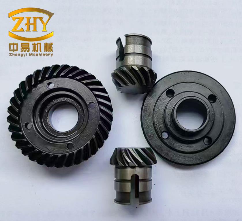
I have spent many years investigating the design, analysis, and manufacturing of screw gears. In this article, I will present my own understanding of the complete production chain, starting from the fundamental geometry of screw gears and ending with the most advanced precision machining methods. Screw gears, often called crossed helical gears, are used to transmit motion between two shafts that are neither parallel nor intersecting. Their teeth follow a cylindrical helix, and the tooth surface contact lines are curves rather than straight lines. This unique configuration gives screw gears several important advantages: a large overlap ratio, a small installation space, smooth transmission, high load-carrying capacity, low energy consumption, and low noise. Because of these characteristics, screw gears are widely applied in aerospace, automotive, heavy machinery, and many other industrial fields. I consider screw gears to be indispensable transmission components in modern industry.
When I analyze screw gears, I always begin with their basic kinematic and geometric relationships. The transmission ratio of a pair of screw gears is determined by the number of teeth and the helix angles. For two screw gears with tooth numbers \(z_1\) and \(z_2\), and helix angles \(\beta_1\) and \(\beta_2\), the ratio can be expressed as:
$$ i = \frac{\omega_1}{\omega_2} = \frac{z_2}{z_1} = \frac{d_2 \cos \beta_2}{d_1 \cos \beta_1} $$
Here, \(\omega_1\) and \(\omega_2\) are the angular velocities, while \(d_1\) and \(d_2\) are the pitch diameters. The lead \(L\) of a screw gear is another critical parameter because it describes how far the gear advances along its axis for one complete revolution. I use the following relationship:
$$ L = \frac{\pi d}{\tan \beta} $$
where \(d\) is the pitch diameter and \(\beta\) is the helix angle. The normal module \(m_n\) and the transverse module \(m_t\) are related through the helix angle:
$$ m_n = m_t \cos \beta $$
For screw gears, the overlap ratio \(\varepsilon_\beta\) is typically much larger than that of spur gears. I calculate it as:
$$ \varepsilon_\beta = \frac{b \tan \beta}{\pi m_t} $$
where \(b\) is the face width. A large overlap ratio means that multiple teeth share the load at the same time, which reduces noise and improves smoothness. These formulas form the foundation of my design and manufacturing decisions for screw gears.
I have summarized the basic geometric parameters of screw gears in the following table. This table helps me quickly verify the consistency of a design before I proceed to manufacturing.
| Parameter | Symbol | Formula or Definition | Typical Value |
|---|---|---|---|
| Number of teeth | \(z\) | Integer | 12–80 |
| Normal module | \(m_n\) | \(m_n = m_t \cos \beta\) | 1–10 mm |
| Transverse module | \(m_t\) | \(m_t = m_n / \cos \beta\) | 1–12 mm |
| Helix angle | \(\beta\) | Angle between tooth and axis | 15°–45° |
| Pitch diameter | \(d\) | \(d = m_t z\) | 20–500 mm |
| Lead | \(L\) | \(L = \pi d / \tan \beta\) | 50–2000 mm |
| Overlap ratio | \(\varepsilon_\beta\) | \(b \tan \beta / (\pi m_t)\) | 1.5–4.0 |
| Pressure angle | \(\alpha_n\) | Normal pressure angle | 20° |
Manufacturing screw gears is a complex task because their tooth surfaces are helical and often curved. Over the years, I have studied and applied several distinct methods. The most common approaches are the unified cutter disk method, hard tooth surface lapping, and hard tooth surface grinding. Each method has its own advantages and limitations, and I choose among them based on batch size, required accuracy, material, and cost. In the following sections, I will explain each method in detail and provide my own observations.
The unified cutter disk method was developed to adapt universal machine tools for small-batch production. When I use this method, I tilt the cutter disk to ensure the rigidity of the gear during machining. The center of the cutter disk remains fixed during the tilting process, which makes the operation simple and repeatable. This method is suitable for small batches of spiral bevel gears, hypoid gears, and zero-degree bevel gears. However, it cannot achieve the high efficiency and precision required for mass production of screw gears. I use it mainly for prototypes and repair work.
Hard tooth surface lapping is a traditional process that I have employed for many years. It effectively reduces tooth surface roughness, corrects tooth profile and lead errors, and improves the contact pattern. The productivity is relatively high. However, lapping has a significant drawback: because the two gears are in a free-fitting state during lapping, it is difficult to ensure uniform rolling across the entire tooth surface. The root and tip regions experience greater relative rolling, while the pitch circle region experiences less. Over a long lapping cycle, this can degrade the tooth profile quality. To control this, I automatically vary the mounting distance, offset distance, and shaft angle during lapping. The following equation describes the relative sliding velocity \(v_s\) at a contact point:
$$ v_s = \sqrt{v_1^2 + v_2^2 – 2 v_1 v_2 \cos \Sigma} $$
where \(v_1\) and \(v_2\) are the tangential velocities of the two screw gears, and \(\Sigma\) is the shaft angle. By monitoring \(v_s\), I can adjust the lapping parameters to avoid excessive wear at the tooth ends. I also use the following formula to estimate the lapping pressure \(p\):
$$ p = \frac{F_n}{A_c} $$
where \(F_n\) is the normal force and \(A_c\) is the contact area. Maintaining a moderate pressure is essential for avoiding surface damage while still removing material.
Hard tooth surface grinding is the most precise method I use for screw gears. It can be divided into generating grinding and profile grinding. In generating grinding, the tool and the gear perform a relative generating motion. The instantaneous velocities of the tool and the gear are equal along the pure rolling path, and a fixed velocity ratio is maintained. The tool cuts the envelope surface of the screw gear. In profile grinding, I use CAD, CNC, and advanced material technologies to achieve an integrated process from digital model to manufacturing. With the widespread adoption of CNC machine tools, profile grinding has become more common. However, because the active screw gear has a different cross-section for each tooth groove, generating grinding is often mandatory for the driving member. I have found that the choice between generating and profile grinding depends on the specific geometry of the screw gears and the required accuracy grade.
The following table compares the three main manufacturing methods for screw gears. I use this table when I need to make a quick decision for a new project.
| Method | Batch Size | Accuracy | Surface Finish | Key Advantage | Main Limitation |
|---|---|---|---|---|---|
| Unified cutter disk | Small | Moderate | Moderate | Simple setup, universal machine | Not for mass production |
| Hard tooth surface lapping | Medium to large | High | Very good | Corrects profile and lead | Non-uniform rolling |
| Hard tooth surface grinding | Medium to large | Very high | Excellent | Highest precision | High equipment cost |
After selecting a method, I follow a well-defined process flow for screw gears. This flow includes rough machining, heat treatment, semi-finish machining, and finish machining. Each stage has its own objectives and critical parameters. I will now describe the entire flow as I typically implement it.
Rough machining removes the bulk of the material from the blank and prepares the screw gears for semi-finish machining. The main methods I use are the cross-section line method, the layer-cutting method, the offset cutting method, and drilling. Among these, the layer-cutting method is the most common because it confines the tool path to a two-dimensional plane. This reduces the number of control programs, simplifies tool path optimization, and minimizes empty cuts. When I perform hobbing to determine the pitch circle thickness, I control the grinding allowance to be within 0.2 mm per side. I also limit the runout of the hobbing process, because excessive runout can cause uneven case depth and reduce the wear resistance of the screw gears. The material removal rate \(Q\) during rough machining can be estimated as:
$$ Q = a_p f_r v_c $$
where \(a_p\) is the depth of cut, \(f_r\) is the feed rate, and \(v_c\) is the cutting speed. I use this formula to balance productivity and tool life.
Heat treatment is a critical step for improving the core mechanical properties of screw gears. I usually apply quenching, nitriding, or carburizing, depending on the application. During heat treatment, the screw gears expand and contract due to temperature changes. The resulting thermal stresses and microstructural stresses can cause distortion. Therefore, I always leave additional machining allowance before heat treatment. The distortion \(\delta\) can be approximated by:
$$ \delta = \alpha \Delta T L $$
where \(\alpha\) is the coefficient of thermal expansion, \(\Delta T\) is the temperature change, and \(L\) is the characteristic length. To minimize distortion, I heat the screw gears uniformly. I often use step heating or control the heating rate between 150 °C/h and 200 °C/h. This reduces the temperature difference between the surface and the core, lowering thermal stresses and microstructural stresses. I also ensure sufficient tempering to relieve residual stresses. During carburizing, I control the carbon potential between 1.0 %C and 1.2 %C to avoid surface peeling during semi-finish machining. After carburizing, I use forced air cooling to accelerate the cooling rate and eliminate network carbides and ferrite. The following table summarizes my typical heat treatment parameters for screw gears.
| Process | Temperature | Time | Atmosphere | Purpose |
|---|---|---|---|---|
| Normalizing | 850–900 °C | 2–4 h | Air | Refine grain, improve machinability |
| Quenching | 820–860 °C | 30–60 min | Oil or polymer | Increase core hardness |
| Tempering | 150–200 °C | 2–3 h | Air | Relieve stresses, improve toughness |
| Carburizing | 900–930 °C | 4–8 h | Endothermic gas | Increase surface hardness |
| Nitriding | 500–550 °C | 10–30 h | Ammonia | Improve wear resistance |
Semi-finish machining of screw gears removes the material left by heat treatment and prepares the tooth surfaces for final finishing. The tooth surface of a screw gear is a complex curved surface. I use a ball-end cutter to perform contour milling on the two tooth flanks of each tooth groove. Because the driving gear is often manufactured by a forming method, its tooth surface is a ruled surface. To avoid interference during cutting, I carefully adjust the tool axis direction and the tool size. I select a smaller-diameter tool for semi-finish machining to reduce the cutting force and minimize deflection. In mass production, I classify the screw gears before semi-finish machining according to size, backlash, and contact position. I use a measuring machine to inspect each gear and then adjust the lapping machine settings accordingly. This classification also helps me detect tooth surface defects. If one gear in a pair has a defect, the lapping process can affect the mating gear, and the defective pair can damage the machine tool fixture. After lapping, I commonly observe interference defects such as top-root contact, excessive contact, and diagonal contact. By mastering the gear process principles and controlling the braking load, lapping time, and machine backlash, I can eliminate these defects.
Finish machining is the final step that brings the screw gears to the required accuracy and surface finish. Lapping is my preferred method for finishing hardened tooth surfaces. It removes residual stresses and heat treatment distortion, improves gear accuracy, and ensures that the contact pattern meets the design requirements. The backlash variation during the lapping cycle must be smaller than the semi-finish allowance to prevent excessive thinning of the teeth. I have also learned that if the driving or driven gear in a pair is scrapped, the remaining good gear can be lapped with a new mating gear. Although a new pair can be produced this way, the good gear must still be matched with an un-lapped mate to ensure proper contact. The following formula gives the lapping cycle time \(t_l\):
$$ t_l = \frac{V_m}{Q_l} $$
where \(V_m\) is the volume of material to be removed and \(Q_l\) is the lapping removal rate. I adjust \(Q_l\) by controlling the lapping pressure, speed, and abrasive concentration.
For precision machining of screw gears, I rely on two main approaches: the generating method and the CNC precision machining method. In the generating method, the installation angle and direction of the cutter change periodically according to the helix angle of the screw gears. This method has a wide application range, high machining accuracy, and good surface finish. During precision machining, the cutter performs a generating motion relative to the workpiece. The variation of the hob installation angle is linearly related to the helix angle of the screw gears. When I set up the machine, I ensure that the pitch surface of the workpiece and the pitch surface of the plane gear perform pure rolling. The hob installation angle, the involute tooth profile, and the helix angle all change periodically according to the design requirements. Because the hobbing principle is based on the conjugate motion between the hob and the screw gears, the hob installation angle must coincide with the helix line of the screw gears. For variable-helix screw gears, each tooth has a different helix angle. I must keep one end of the hob fixed and swing the other end according to the helix angle variation. The following equation describes the hob setting angle \(\gamma\):
$$ \gamma = \beta \pm \alpha_n $$
where \(\beta\) is the helix angle and \(\alpha_n\) is the normal pressure angle. The sign depends on the direction of the helix and the cutter rotation.
CNC precision machining allows me to perform three-axis simultaneous control and even more complex联动. The number of linkage axes determines the complexity of the tooth surface that can be produced. More axes lead to higher accuracy and more complex shapes. In a typical CNC setup, the tool is fixed on the Z-axis and can only move up and down along that axis. Therefore, I choose a fixture that performs the swinging motion. To ensure coaxiality between the axes, the fixture is usually limited to movement in the X and Y directions. Because the helix angle of each tooth causes a different lead value, I must control the tool path through a dedicated program that follows the helix angle variation. This enables precise machining of screw gears. The tool path \(P(t)\) can be parameterized as:
$$ P(t) = \begin{bmatrix} R \cos(\theta(t)) \\ R \sin(\theta(t)) \\ L \frac{\theta(t)}{2\pi} \end{bmatrix} $$
where \(R\) is the pitch radius, \(\theta(t)\) is the rotation angle, and \(L\) is the lead. By synchronizing the rotational and axial motions, I achieve the required helical surface on the screw gears.
Quality control is essential throughout the manufacturing of screw gears. I use several inspection methods, including profile measurement, lead measurement, pitch measurement, and contact pattern inspection. The following table lists common defects that I encounter and their possible causes. I use this table to troubleshoot production problems quickly.
| Defect | Possible Cause | Corrective Action |
|---|---|---|
| Tooth profile error | Incorrect cutter profile, wear, or setup | Re-dress cutter, reset machine |
| Lead error | Incorrect helix angle, guide error | Adjust guide, check lead |
| Pitch error | Indexing error, thermal distortion | Calibrate index, control temperature |
| Top-root contact | Excessive lapping, wrong mounting distance | Reduce lapping time, adjust distance |
| Diagonal contact | Misalignment, incorrect shaft angle | Realign, adjust angle |
| Surface peeling | Excessive carbon potential, improper cooling | Control carburizing, improve cooling |
I also use the contact ratio \(\varepsilon_\alpha\) to evaluate the load-sharing capability of screw gears. It is defined as:
$$ \varepsilon_\alpha = \frac{\sqrt{r_{a1}^2 – r_{b1}^2} + \sqrt{r_{a2}^2 – r_{b2}^2} – a \sin \alpha_w}{\pi m_t \cos \alpha_t} $$
where \(r_a\) is the tip radius, \(r_b\) is the base radius, \(a\) is the center distance, \(\alpha_w\) is the working pressure angle, and \(\alpha_t\) is the transverse pressure angle. A higher contact ratio means smoother operation and lower noise. For screw gears, the total contact ratio is the sum of the transverse contact ratio and the overlap ratio:
$$ \varepsilon = \varepsilon_\alpha + \varepsilon_\beta $$
I always aim for a total contact ratio greater than 2.0 to ensure reliable performance.
In my experience, the selection of materials for screw gears is also a key factor. I typically use low-carbon alloy steels such as 20CrMnTi, 20CrNiMo, or 42CrMo. For high-speed applications, I may use nitriding steels. The material hardness after heat treatment usually ranges from 58 to 62 HRC for the tooth surface, while the core hardness is kept between 30 and 45 HRC. The following table summarizes my material selection guidelines for screw gears.
| Application | Material | Heat Treatment | Surface Hardness | Core Hardness |
|---|---|---|---|---|
| Automotive transmission | 20CrMnTi | Carburizing and quenching | 58–62 HRC | 30–42 HRC |
| Aerospace | 9310 | Carburizing and quenching | 60–64 HRC | 35–45 HRC |
| Heavy machinery | 42CrMo | Nitriding | 55–60 HRC | 28–35 HRC |
| High-speed spindle | 20CrNiMo | Carburizing and quenching | 58–62 HRC | 32–40 HRC |
During rough machining, I also pay close attention to the cutting parameters. The following table provides my recommended ranges for hobbing and milling screw gears. These values depend on the material, tool material, and machine rigidity, so I always fine-tune them according to the actual conditions.
| Operation | Cutting Speed (m/min) | Feed Rate (mm/rev) | Depth of Cut (mm) | Tool Material |
|---|---|---|---|---|
| Rough hobbing | 80–120 | 1.5–3.0 | 2–6 | Coated carbide |
| Semi-finish milling | 120–180 | 0.5–1.5 | 0.3–1.0 | Coated carbide |
| Finish hobbing | 60–100 | 0.8–1.5 | 0.1–0.3 | HSS or carbide |
| Hard grinding | 25–45 | 0.1–0.5 | 0.02–0.1 | Aluminum oxide or CBN |
I also perform a final inspection of the screw gears after all machining operations. The inspection includes checking the tooth thickness, backlash, runout, and contact pattern. The tooth thickness \(s_n\) at the normal plane is calculated as:
$$ s_n = m_n \left( \frac{\pi}{2} + 2 x \tan \alpha_n \right) $$
where \(x\) is the profile shift coefficient. The backlash \(j_n\) between two screw gears is given by:
$$ j_n = j_{n1} + j_{n2} + j_{n3} $$
where \(j_{n1}\) is the backlash due to center distance deviation, \(j_{n2}\) is due to tooth thickness deviation, and \(j_{n3}\) is due to thermal expansion. I keep the backlash within the tolerance specified by the application, typically between 0.05 mm and 0.3 mm.
In conclusion, I have described the complete manufacturing process for screw gears based on my own experience. I began with the geometry and kinematics of screw gears, then discussed the main manufacturing methods: the unified cutter disk method, hard tooth surface lapping, and hard tooth surface grinding. I explained the process flow, including rough machining, heat treatment, semi-finish machining, and finish machining. I also presented precision machining methods such as generating and CNC machining. Throughout the article, I used tables and formulas to summarize the key parameters and relationships. Screw gears are complex components, but with careful design, proper material selection, and precise manufacturing, they can deliver excellent performance in a wide range of applications. I am confident that continued advances in CNC technology and cutting tools will further improve the quality and efficiency of screw gear production.