
I investigate a compact transmission concept that is intended for intelligent robotic joints, where high reduction, large torque capacity, small volume, and long-term backlash stability must coexist. The concept I develop is a beveloid internal gear enveloping external-rotor crown worm drive. In the broader classification of mechanical power transmission, this arrangement belongs to the family of screw gears, because its meshing action combines rolling and sliding along skewed axes. Unlike ordinary screw gears, however, the present drive uses a crown worm generated by a beveloid internal gear, and it integrates the worm with an external-rotor permanent-magnet motor. My purpose is to establish the meshing theory, derive the principal performance metrics, and evaluate how the main geometric parameters affect contact-line distribution, induced normal curvature, lubrication angle, and relative entrainment velocity.
I begin from the observation that many existing robot joint reducers have limitations. Cycloidal and harmonic reducers can be compact and precise, but they often involve complex manufacturing, compliance, and difficult wear compensation. Planetary reducers are robust, yet they may be bulky when high ratios are required. Worm drives offer high reduction ratios and compact layouts, but conventional cylindrical worm gears often suffer from unfavorable sliding, thermal problems, and limited load capacity. Enveloping worm drives improve load sharing and contact length, and crown worm drives further increase conformity. The design I analyze here pushes those advantages into an internal-meshing configuration, creating a drive that behaves as a specialized set of screw gears with large overlap and strong load-sharing potential.
The central mechanical idea is that the internal gear is a beveloid internal gear with unequal flank inclination on its two sides. This variable tooth thickness allows axial displacement of the internal gear to adjust backlash and compensate wear. The crown worm is generated as the conjugate envelope of this internal gear. Because the axis angle between the crown worm and the internal gear is \(90^\circ\), the transmission can be arranged so that the worm lies inside the internal gear. I combine the crown worm with an external-rotor permanent-magnet motor, so the motor rotor and the worm form one compact unit. The result is a three-in-one intelligent joint concept containing a servo motor, a reducer, and an integrated sensing system. In my view, this arrangement is especially attractive for modular robot joints because it reduces part count, axial length, and overall mass.
In the analysis that follows, I treat the drive as a spatial meshing problem. I establish fixed and moving coordinate frames, derive the relative velocity and relative angular velocity, obtain the meshing equation, formulate the contact-line equation for the internal gear, and generate the worm tooth surface. I then derive the induced normal curvature, the lubrication angle, and the relative entrainment velocity. These quantities are the key indicators of meshing performance for screw gears in general and for this crown worm drive in particular. Finally, I perform a parameter study focused on the worm throat diameter coefficient, the main base circle diameter, and the generating plane inclination angle. My aim is to provide a clear design-oriented understanding rather than a purely descriptive account.
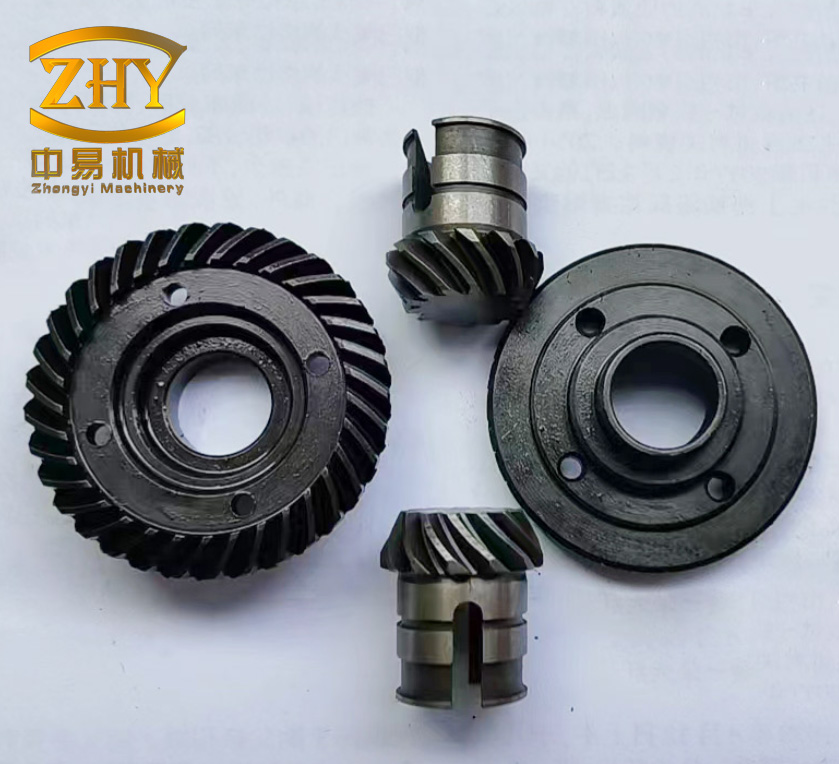
Transmission Principle and Design Rationale
I consider a crown worm that rotates about one axis while a beveloid internal gear rotates about a perpendicular axis. The internal gear has wedge-shaped teeth. Its two flanks are not symmetric in the same way as a standard spur or helical internal gear. Because the tooth thickness varies along the axial direction, moving the internal gear axially changes the effective clearance between the worm and the internal gear teeth. This gives me a direct mechanism for backlash adjustment and wear compensation. The adjustment principle differs from axial worm adjustment, circumferential worm-wheel adjustment, or center-distance adjustment. Instead, the variable tooth thickness itself becomes the control feature.
From the viewpoint of screw gears, this is important because backlash control in screw gears is often difficult. Screw gears transmit motion between non-parallel, non-intersecting axes, and their contact conditions are sensitive to small changes in center distance, shaft angle, and axial position. A beveloid internal gear gives me an additional, deliberate degree of freedom. I can shift the internal gear along its axis to restore a desired meshing condition after wear. This is a practical advantage for robotic joints, where repeatability and lost motion must remain stable over many operating cycles.
The external-rotor motor integration is equally important. In a conventional layout, the motor, reducer, and encoder are separate modules. I instead place the stator on a fixed shaft and let the external rotor carry the crown worm. The internal gear can be supported as a rotary bearing structure, and a high-resolution circular grating can be mounted for position feedback. The transmission therefore becomes a compact joint module. The worm sits inside the internal gear, which makes the radial envelope smaller than many external-meshing alternatives. For a robot joint, this internal arrangement can reduce the distance from the joint axis to the outer housing and simplify cable routing.
I also note that the proposed drive inherits several advantages of enveloping worm transmissions. These include multiple teeth in contact, large contact ratio, long total contact-line length, and high load capacity. At the same time, the internal mesh and the beveloid geometry introduce new behavior. The contact lines are not simply scaled versions of those in a planar internal gear enveloping drive. The variable tooth thickness changes the effective generating plane position, and the axial adjustment changes the meshing zone. Therefore, I need a full spatial meshing formulation before I can make design recommendations.
Coordinate Systems and Kinematic Definitions
I set up two fixed reference frames and two moving frames. Let \(\Sigma_1′(O_1′; \mathbf{i}_1′, \mathbf{j}_1′, \mathbf{k}_1′)\) and \(\Sigma_2′(O_2′; \mathbf{i}_2′, \mathbf{j}_2′, \mathbf{k}_2′)\) be the fixed frames associated with the crown worm and the internal gear, respectively. Let \(\Sigma_1(O_1; \mathbf{i}_1, \mathbf{j}_1, \mathbf{k}_1)\) and \(\Sigma_2(O_2; \mathbf{i}_2, \mathbf{j}_2, \mathbf{k}_2)\) be the corresponding moving frames. The crown worm rotates about the \(\mathbf{k}_1\) axis with angular velocity \(\omega_1\). The internal gear rotates about the \(\mathbf{k}_2\) axis with angular velocity \(\omega_2\). The instantaneous rotation angles are \(\varphi_1\) and \(\varphi_2\). The speed ratio satisfies
$$ \frac{\varphi_1}{\varphi_2} = \frac{\omega_1}{\omega_2} = \frac{Z_2}{Z_1} = i_{12}, $$
where \(Z_1\) is the number of worm threads or starts, \(Z_2\) is the number of internal gear teeth, and \(i_{12}\) is the transmission ratio from the worm to the internal gear. I also define \(i_{21}=1/i_{12}\). When \(\varphi_1=\varphi_2=0\), the moving frames coincide with the fixed frames.
The generating plane is located in the internal gear frame. I introduce an auxiliary frame \(\Sigma_3(O_3; \mathbf{i}_3, \mathbf{j}_3, \mathbf{k}_3)\). Its origin \(O_3\) has coordinates \((r_b,0,0)\) in \(\Sigma_2\). The unit vector \(\mathbf{i}_3\) is parallel to \(\mathbf{j}_2\), and the angle between \(\mathbf{j}_3\) and \(\mathbf{k}_2\) is the generating plane inclination angle \(\beta\). The main base circle radius is \(r_b\). Let \(\mathbf{n}\) be the unit normal of the generating plane, and let \(u\) and \(v\) be orthogonal plane parameters. I also introduce an activity frame \(\Sigma_p(P; \mathbf{e}_1, \mathbf{e}_2, \mathbf{e}_3)\) at an arbitrary meshing point \(P\), with \(\mathbf{e}_1\) parallel to \(\mathbf{i}_3\) and \(\mathbf{e}_3\) normal to the generating plane. This activity frame is convenient for curvature and lubrication calculations.
| Symbol | Meaning |
|---|---|
| \(\Sigma_1′,\Sigma_2’\) | Fixed frames of crown worm and internal gear |
| \(\Sigma_1,\Sigma_2\) | Moving frames of crown worm and internal gear |
| \(\Sigma_3\) | Generating plane frame |
| \(\Sigma_p\) | Activity frame at a meshing point |
| \(a\) | Center distance between axes |
| \(i_{12},i_{21}\) | Transmission ratio and its inverse |
| \(\varphi_1,\varphi_2\) | Instantaneous rotation angles |
| \(r_b\) | Main base circle radius |
| \(\beta\) | Generating plane inclination angle |
| \(u,v\) | Orthogonal parameters on the generating plane |
| \(\mathbf{v}^{(12)}\) | Relative velocity at a meshing point |
| \(\boldsymbol{\omega}^{(12)}\) | Relative angular velocity |
| \(\Phi\) | Meshing function |
| \(k_\delta\) | Induced normal curvature |
| \(\mu\) | Lubrication angle |
| \(v_{jx}\) | Relative entrainment velocity |
For the kinematic analysis, I set the worm angular velocity to \(1\ \mathrm{rad/s}\) without loss of generality. Then \(\omega^{(2)}=i_{21}\ \mathrm{rad/s}\). This normalization simplifies the expressions and does not change the geometrical trends. In a real screw gears application, the absolute speed scales the velocities, but the normalized contact and lubrication indicators remain useful for comparing designs.
Relative Velocity and Relative Angular Velocity
I write the general relative velocity at a meshing point as
$$ \mathbf{v}^{(12)} = \mathbf{v}_0^{(1)} – \mathbf{v}_0^{(2)} + \boldsymbol{\omega}^{(1)} \times \mathbf{r}^{(1)} – \boldsymbol{\omega}^{(2)} \times \mathbf{r}^{(2)}. $$
Here \(\mathbf{v}_0^{(1)}\) and \(\mathbf{v}_0^{(2)}\) are the velocities of the origins of the moving frames, \(\boldsymbol{\omega}^{(1)}\) and \(\boldsymbol{\omega}^{(2)}\) are the angular velocity vectors, and \(\mathbf{r}^{(1)}\) and \(\mathbf{r}^{(2)}\) are the position vectors of the contact point in the two moving frames. In the first envelope generation, the origins of the moving frames are fixed, so \(\mathbf{v}_0^{(1)}=\mathbf{v}_0^{(2)}=0\). This reduces the relative velocity to the rotational terms. In the internal gear frame \(\Sigma_2\), I obtain the component form
$$ \mathbf{v}_2^{(12)} = v_{2x}^{(12)}\mathbf{i}_2 + v_{2y}^{(12)}\mathbf{j}_2 + v_{2z}^{(12)}\mathbf{k}_2, $$
$$ v_{2x}^{(12)} = z_2\sin\varphi_2 – y_2 i_{21}, $$
$$ v_{2y}^{(12)} = -z_2\cos\varphi_2 + x_2 i_{21}, $$
$$ v_{2z}^{(12)} = a + y_2\cos\varphi_2 – x_2\sin\varphi_2. $$
Similarly, the relative angular velocity in \(\Sigma_2\) is
$$ \boldsymbol{\omega}_2^{(12)} = \omega_{2x}^{(12)}\mathbf{i}_2 + \omega_{2y}^{(12)}\mathbf{j}_2 + \omega_{2z}^{(12)}\mathbf{k}_2, $$
$$ \omega_{2x}^{(12)} = \cos\varphi_2, $$
$$ \omega_{2y}^{(12)} = \sin\varphi_2, $$
$$ \omega_{2z}^{(12)} = i_{21}. $$
These expressions are the foundation for the meshing condition. For screw gears, the relative motion is a combination of rotation about the instantaneous axis and translation along the tooth direction. The meshing condition extracts the component of this motion that lies in the common tangent plane. When that component vanishes along the normal, the surfaces are conjugate.
Meshing Function and Meshing Equation
From spatial meshing theory, two tooth surfaces mesh correctly when their common normal at the contact point is perpendicular to the relative velocity. I express this condition as
$$ \Phi = \mathbf{n}^{(2)} \cdot \mathbf{v}^{(12)} = 0. $$
After coordinate transformation, I write the meshing function for the first envelope as
$$ \Phi = N_1\sin\varphi_2 + N_2\cos\varphi_2 + N_3, $$
where
$$ N_1 = -v + r_b\sin\beta, $$
$$ N_2 = u\sin\beta, $$
$$ N_3 = i_{21}u\cos\beta – a\sin\beta. $$
Setting \(\Phi=0\) gives the meshing equation. I solve for the plane parameter \(v\) and obtain
$$ v = \frac{-u i_{21}\cos\beta + \sin\beta\left(r_b\sin\varphi_2 + u\cos\varphi_2 – a\right)}{\sin\varphi_2}. $$
This equation is central to my analysis. It defines the instantaneous contact line on the generating plane. For a given rotation angle \(\varphi_2\), the parameters \(u\) and \(v\) that satisfy this relation form the contact path. As \(\varphi_2\) varies, the contact line sweeps through the generating plane and creates the conjugate tooth surface. In the language of screw gears, this is the kinematic heart of the transmission: the meshing equation enforces the correct ratio between rotational motion and surface generation.
I emphasize that the denominator \(\sin\varphi_2\) indicates a singular behavior near \(\varphi_2=0\). In practice, the design avoids operation at this singular position, or it treats the limit carefully. The singular condition corresponds to a degeneracy in the instantaneous contact geometry. For robust screw gears, the nominal meshing zone should be placed away from such degeneracies. My parameter study therefore focuses on the normal operating range rather than the singular limit.
Contact Lines and Generated Worm Tooth Surface
The contact line on the internal gear tooth surface is obtained by combining the generating plane coordinates with the meshing equation. In the internal gear frame, I write
$$ \mathbf{r}_2^{(2)} = x_2\mathbf{i}_2 + y_2\mathbf{j}_2 + z_2\mathbf{k}_2, $$
$$ x_2 = r_b – v\sin\beta, $$
$$ y_2 = -u, $$
$$ z_2 = v\cos\beta, $$
$$ \Phi = 0. $$
Substituting the meshing equation into these coordinates gives the contact line for each angular position. The contact line is not a straight line in physical space because the generating plane orientation and the relative motion combine to produce a curved spatial path. For the internal gear, the contact line moves across the tooth flank as the gear rotates. The envelope of these lines forms the worm tooth surface.
When the generating plane moves continuously with \(\varphi_2\), the worm tooth surface in the worm moving frame \(\Sigma_1\) is
$$ x_2 = r_b – v\sin\beta, $$
$$ y_2 = -u, $$
$$ z_2 = v\cos\beta, $$
$$ v = \frac{-u i_{21}\cos\beta + \sin\beta\left(r_b\sin\varphi_2 + u\cos\varphi_2 – a\right)}{\sin\varphi_2}, $$
$$ x_1 = -x_2\cos\varphi_1\sin\varphi_2 + y_2\cos\varphi_1\cos\varphi_2 + z_2\sin\varphi_1 + a\cos\varphi_1, $$
$$ y_1 = x_2\sin\varphi_1\sin\varphi_2 – y_2\sin\varphi_1\cos\varphi_2 + z_2\cos\varphi_1 – a\sin\varphi_1, $$
$$ z_1 = x_2\cos\varphi_2 + y_2\sin\varphi_2. $$
These equations define the crown worm surface as the conjugate envelope of the beveloid internal gear. I use them to generate the worm geometry numerically. The resulting surface is a spatial screw-like surface. This is why the drive can be viewed as a specialized member of the screw gears family, although its overall layout is that of a crown worm and an internal gear.
I find it useful to distinguish three features of the contact pattern. First, the contact lines may cross within the meshing zone. The crossing region is sometimes called a secondary action region, because a point on the worm surface may contact the internal gear more than once during the overall meshing cycle. Second, the density of contact lines indicates how many teeth share the load. A denser set of lines across several teeth generally means higher load capacity. Third, the orientation of the contact lines relative to the sliding velocity controls lubrication and wear. A contact line that is nearly perpendicular to the sliding velocity tends to produce a large lubrication angle, which is favorable. I use these features throughout my parameter analysis.
Induced Normal Curvature
The induced normal curvature is one of the most important indicators of contact stress and conformity in screw gears. I define it along the direction normal to the contact line. Using the activity frame, I write
$$ k_\delta = \frac{(\omega_{3y}^{(12)})^2 + (\omega_{3x}^{(12)})^2}{\Psi}, $$
where \(\Psi\) is the first kind function of the transmission,
$$ \Psi = \Phi_t + \omega_{3y}^{(12)}v_{3x}^{(12)} – \omega_{3x}^{(12)}v_{3y}^{(12)}, $$
and \(\Phi_t\) is the second kind function,
$$ \Phi_t = i_{21}\cos\varphi_2\left(-v + r_b\sin\beta\right) – i_{21}\sin\varphi_2 u\sin\beta. $$
Here \(v_{3x}^{(12)}\), \(v_{3y}^{(12)}\), \(\omega_{3x}^{(12)}\), and \(\omega_{3y}^{(12)}\) are the components of relative velocity and relative angular velocity in the activity frame along \(\mathbf{i}_3\) and \(\mathbf{j}_3\). A smaller induced normal curvature means that the two surfaces are more conformal. Greater conformity usually reduces contact stress, improves load capacity, and can improve elastohydrodynamic lubrication. For screw gears, conformity is not uniform along the contact line, so I evaluate \(k_\delta\) over the full meshing cycle.
I interpret the sign and magnitude of \(k_\delta\) carefully. The denominator \(\Psi\) contains the meshing function derivative and the relative motion components. If \(\Psi\) approaches zero, the induced curvature can become very large, indicating a risk of edge contact or severe local stress. In my numerical studies, I therefore monitor \(\Psi\) as well as \(k_\delta\). The design objective is not simply to minimize curvature at one point, but to keep the curvature and the first-kind function within acceptable bounds across the entire contact zone.
Lubrication Angle
The lubrication angle measures the angle between the relative velocity direction and the contact-line tangent direction. I compute it as
$$ \mu = \arcsin\left(\frac{v_{3x}^{(12)}\omega_{3y}^{(12)} – v_{3y}^{(12)}\omega_{3x}^{(12)}}{\sqrt{(v_{3x}^{(12)})^2+(v_{3y}^{(12)})^2}\sqrt{(\omega_{3y}^{(12)})^2+(\omega_{3x}^{(12)})^2}}\right). $$
A lubrication angle near \(90^\circ\) is favorable because the sliding velocity is nearly perpendicular to the contact line. This condition helps the lubricant entrain into the contact and form a film. A small lubrication angle means that the relative motion is more nearly parallel to the contact line, so the lubricant is less effectively drawn into the contact. In screw gears, the lubrication angle is often a decisive factor for scuffing resistance and thermal performance. I therefore treat \(\mu\) as a primary design objective.
I also note that the lubrication angle is not constant during meshing. It changes from the beginning of contact to the end of contact. A design with a high average lubrication angle and small variation is generally preferable to one with a high peak but a deep minimum. In my parameter study, I examine both the mean value and the range of \(\mu\).
Relative Entrainment Velocity
The relative entrainment velocity describes how quickly the contacting surfaces draw lubricant through the contact. I use
$$ v_{jx} = \frac{v_{3x}^{(12\Sigma)}\omega_{3y}^{(12)} – v_{3y}^{(12\Sigma)}\omega_{3x}^{(12)}}{2\sqrt{(\omega_{3x}^{(12)})^2+(\omega_{3y}^{(12)})^2}}, $$
where \(v_{3x}^{(12\Sigma)}\) and \(v_{3y}^{(12\Sigma)}\) are the components of the sum velocity in the activity frame. A larger entrainment velocity generally improves film thickness, because more lubricant is carried into the contact per unit time. However, a larger entrainment velocity is not automatically beneficial if it is accompanied by a small lubrication angle or a large induced curvature. I therefore evaluate \(v_{jx}\) together with \(k_\delta\) and \(\mu\).
From a design perspective, the relative entrainment velocity is a useful indicator of thermal and lubrication behavior. If \(v_{jx}\) is too low, the contact may run hot and wear quickly. If \(v_{jx}\) is high but the contact pressure is also high, the design may still be acceptable because the lubricant film can carry the load. The best design balances entrainment, conformity, and contact-line orientation.
| Metric | Symbol | Desired trend | Physical meaning |
|---|---|---|---|
| Induced normal curvature | \(k_\delta\) | Smaller | Higher conformity and lower contact stress |
| Lubrication angle | \(\mu\) | Closer to \(90^\circ\) | Better lubricant entrainment and scuffing resistance |
| Relative entrainment velocity | \(v_{jx}\) | Larger, within thermal limits | Improved film formation and heat transport |
| Contact-line density | Qualitative | Higher over multiple teeth | Greater load sharing and capacity |
| Secondary action region | Qualitative | Controlled or eliminated | Reduced risk of repeated contact and wear |
Parameter Study: Worm Throat Diameter Coefficient
I now examine how the worm throat diameter coefficient \(k\) affects the meshing performance. I define \(k\) as a scaling parameter that relates the worm throat diameter to the center distance. In practical design, \(k\) controls how slim or bulky the crown worm appears in the throat region. My numerical calculations show several consistent trends.
As \(k\) increases, the contact region of the internal gear increases slightly. At the same time, the crossing point of the contact lines, which defines the secondary action region, tends to disappear. This means the contact pattern becomes simpler and more predictable. However, the number of teeth in simultaneous mesh decreases. This is a trade-off: a larger \(k\) gives a cleaner contact pattern, but it reduces the total number of teeth sharing the load. For high-torque robot joints, this reduction in load sharing may be undesirable. For high-speed or lightly loaded operation, the cleaner contact pattern may be attractive.
The induced normal curvature decreases as \(k\) increases from meshing entry to meshing exit. A smaller \(k_\delta\) is favorable for contact stress. Therefore, increasing \(k\) tends to improve conformity. The lubrication angle increases with \(k\), which means that a larger \(k\) improves the orientation of the sliding velocity relative to the contact line. The relative entrainment velocity also increases with \(k\). These trends suggest that a larger worm throat diameter coefficient improves lubrication and entrainment, but at the cost of fewer teeth in contact.
| Quantity | Trend with increasing \(k\) | Design implication |
|---|---|---|
| Contact region size | Slight increase | More area may be available for load distribution |
| Secondary action region | Disappears | Simpler contact pattern and lower risk of repeated contact |
| Number of teeth in mesh | Decreases | Lower load sharing, so torque capacity may fall |
| Induced normal curvature \(k_\delta\) | Decreases | Higher conformity and lower contact stress |
| Lubrication angle \(\mu\) | Increases | Better lubricant entrainment |
| Relative entrainment velocity \(v_{jx}\) | Increases | Improved film formation and cooling |
I therefore treat \(k\) as a balancing parameter. If the primary requirement is maximum torque capacity, I prefer a smaller \(k\) so that more teeth remain in contact. If the primary requirement is smooth lubrication and low curvature, I prefer a larger \(k\). In a robotic joint, the duty cycle usually includes both high-torque quasi-static phases and high-speed positioning phases. A compromise value of \(k\) is therefore necessary. I would select \(k\) after evaluating the expected load spectrum and the thermal environment.
Parameter Study: Main Base Circle Diameter
I next examine the main base circle diameter \(d_b=2r_b\). The main base circle defines the position of the generating plane in the internal gear frame. It is therefore a fundamental geometric parameter. My calculations show that its influence is weaker than that of the generating plane inclination angle, but it is still important for fine tuning.
As \(d_b\) increases, the contact region of the internal gear increases slightly, and the secondary action region tends to disappear. This is similar to the effect of increasing \(k\), but the magnitude is smaller. The number of teeth in mesh is not strongly affected over the range I studied. This means that \(d_b\) can be adjusted to improve the contact pattern without drastically changing the load-sharing behavior.
The induced normal curvature shows a more complex trend. At the meshing entry, \(k_\delta\) increases with \(d_b\). Around \(\varphi_2=22^\circ\), the induced normal curvature remains nearly constant at approximately \(0.025\ \mathrm{mm}^{-1}\) and does not change significantly with \(d_b\). After that point, \(k_\delta\) decreases as \(d_b\) increases. This means that the effect of \(d_b\) on curvature depends on the phase of meshing. A design change that improves curvature at exit may worsen it at entry. I therefore evaluate the full cycle rather than a single point.
The lubrication angle first decreases and then increases as \(d_b\) increases. The relative entrainment velocity also first decreases and then increases. These non-monotonic trends indicate that there is an intermediate value of \(d_b\) where lubrication and entrainment reach a minimum. That value is generally not desirable. I would choose \(d_b\) away from this minimum, either on the smaller side or the larger side, depending on the other constraints. Because the overall influence of \(d_b\) is moderate, I treat it as a secondary design parameter.
| Quantity | Trend with increasing \(d_b\) | Design implication |
|---|---|---|
| Contact region size | Slight increase | Modest improvement in contact area |
| Secondary action region | Tends to disappear | More predictable contact pattern |
| Number of teeth in mesh | Weakly affected | Can be tuned without large changes in load sharing |
| Induced normal curvature \(k_\delta\) | Increases near entry; nearly constant near mid-cycle; decreases near exit | Full-cycle evaluation is required |
| Lubrication angle \(\mu\) | First decreases, then increases | Avoid the intermediate minimum |
| Relative entrainment velocity \(v_{jx}\) | First decreases, then increases | Avoid the intermediate minimum |
My overall assessment is that \(d_b\) is a fine-tuning parameter. It can improve the contact pattern and shift the curvature distribution, but it does not dominate the meshing performance. In a screw gears design workflow, I would fix \(d_b\) after the main proportions are established and then use it to optimize the contact-line pattern.
Parameter Study: Generating Plane Inclination Angle
The generating plane inclination angle \(\beta\) is the most influential parameter in my study. It determines the orientation of the generating plane and therefore controls the shape and position of the contact lines. As \(\beta\) increases, the contact region of the internal gear shifts to the right and becomes larger. The contact lines become more dispersed. The secondary action region gradually decreases and eventually disappears. At the same time, the number of teeth in contact decreases. This means that \(\beta\) strongly affects the trade-off between contact area and load sharing.
The induced normal curvature increases with \(\beta\) from meshing entry to meshing exit. A larger \(\beta\) therefore tends to reduce conformity and increase contact stress. This is an important counter-effect. Although a larger \(\beta\) disperses the contact lines and may improve lubrication, it also increases curvature. I must therefore avoid making \(\beta\) too large unless the lubrication benefit outweighs the stress penalty.
The lubrication angle increases with \(\beta\). At \(\beta=40^\circ\), the lubrication angle remains greater than \(82^\circ\) over the entire meshing cycle. This is an excellent result for lubricant entrainment. At \(\beta=20^\circ\), the lubrication angle varies widely, which means that some portions of the meshing cycle may have poor lubrication. The relative entrainment velocity also increases with \(\beta\). These results show that \(\beta\) is the primary control parameter for lubrication performance in this screw gears arrangement.
| Quantity | Trend with increasing \(\beta\) | Design implication |
|---|---|---|
| Contact region position | Shifts right and enlarges | Changes the effective meshing zone |
| Contact-line dispersion | Increases | More distributed contact, but fewer teeth may share load |
| Secondary action region | Decreases until it disappears | Lower risk of repeated contact |
| Number of teeth in mesh | Decreases | Lower load sharing |
| Induced normal curvature \(k_\delta\) | Increases | Lower conformity and higher contact stress |
| Lubrication angle \(\mu\) | Increases | At \(\beta=40^\circ\), \(\mu>82^\circ\) over the full cycle |
| Relative entrainment velocity \(v_{jx}\) | Increases | Improved lubricant transport |
I conclude that \(\beta\) should be selected with great care. A larger \(\beta\) gives better lubrication but poorer conformity. A smaller \(\beta\) gives better conformity and more teeth in contact but a more variable lubrication angle. The optimal \(\beta\) depends on the balance between torque capacity, thermal limits, and wear resistance. For a robot joint that experiences high torque at low speed, I would favor a smaller \(\beta\) to maintain conformity and load sharing. For a joint that experiences high speed and thermal stress, I would favor a larger \(\beta\) to improve lubrication.
Combined Parametric Interpretation
I now combine the individual parameter effects into a unified design perspective. The worm throat diameter coefficient \(k\) primarily controls the number of teeth in contact and the general level of conformity. The main base circle diameter \(d_b\) provides fine adjustment of the contact pattern. The generating plane inclination angle \(\beta\) controls the contact-line distribution and dominates the lubrication angle. These three parameters interact, so I cannot optimize them independently.
In my design workflow, I first choose \(k\) to achieve the required load-sharing level. If the joint must transmit high torque, I reduce \(k\) so that more teeth share the load. If the joint must operate at high speed with low torque, I increase \(k\) to improve lubrication and reduce curvature. I then choose \(\beta\) to achieve the desired lubrication angle. A value around \(40^\circ\) gives excellent lubrication but may increase curvature. A value around \(20^\circ\) gives better conformity but a wider variation in lubrication angle. Finally, I use \(d_b\) to fine-tune the contact pattern and avoid the intermediate minimum in lubrication and entrainment.
| Parameter | Primary influence | Secondary influence | Recommended role |
|---|---|---|---|
| \(k\) | Number of teeth in mesh and conformity | Lubrication and entrainment | Set first according to load requirement |
| \(d_b\) | Contact pattern and curvature distribution | Lubrication and entrainment | Fine-tune after \(k\) and \(\beta\) |
| \(\beta\) | Contact-line distribution and lubrication angle | Curvature and load sharing | Set according to thermal and wear requirements |
I also consider the practical issue of backlash adjustment. The beveloid internal gear allows axial displacement to change the effective tooth thickness. This is a major advantage because it decouples backlash control from the primary meshing geometry. I can design the nominal contact pattern for good load sharing and lubrication, and then use axial adjustment to remove clearances that develop over time. This is particularly valuable in screw gears, where wear can otherwise change the contact pattern significantly.
Numerical Observations and Trends
My numerical calculations cover a range of \(k\), \(d_b\), and \(\beta\). I summarize the main observations as follows. For \(k\), the induced curvature decreases monotonically from entry to exit as \(k\) increases. The lubrication angle increases monotonically. The entrainment velocity increases monotonically. The contact pattern becomes cleaner, but the number of teeth in mesh falls. For \(d_b\), the curvature effect is phase-dependent. Near entry, curvature increases with \(d_b\). Near mid-cycle, curvature is almost constant. Near exit, curvature decreases with \(d_b\). The lubrication angle and entrainment velocity both have a minimum at an intermediate \(d_b\). For \(\beta\), curvature, lubrication angle, and entrainment velocity all increase. The contact region shifts and enlarges, and the secondary action region disappears.
These trends can be represented in a qualitative sensitivity table. I use this table when I compare candidate designs. A plus sign means that the quantity increases with the parameter. A minus sign means that it decreases. A U-shape means that the quantity first decreases and then increases.
| Performance quantity | \(k\) | \(d_b\) | \(\beta\) |
|---|---|---|---|
| Contact region size | + (slight) | + (slight) | + |
| Secondary action region | Disappears | Disappears | Disappears |
| Number of teeth in mesh | \(-\) | Weak | \(-\) |
| Induced normal curvature \(k_\delta\) | \(-\) | Phase-dependent | + |
| Lubrication angle \(\mu\) | + | U-shape | + |
| Relative entrainment velocity \(v_{jx}\) | + | U-shape | + |
I find that the most robust designs are those that avoid extreme values of any single parameter. A very small \(k\) gives many teeth in contact but poor lubrication. A very large \(k\) gives good lubrication but few teeth in contact. A very small \(\beta\) gives good conformity but variable lubrication. A very large \(\beta\) gives excellent lubrication but high curvature. A very small or very large \(d_b\) may improve one phase of meshing while worsening another. The best compromise is usually found in the middle of the feasible ranges, with final adjustment based on the specific duty cycle.
Comparison with Conventional Screw Gears and Worm Drives
It is useful to compare the proposed drive with conventional screw gears and worm drives. In a standard cylindrical worm gear, the contact lines are often concentrated on a small portion of the worm thread. The lubrication angle can be unfavorable, and the load capacity is limited by the number of threads in contact. In a double-enveloping worm drive, the worm and gear wrap around each other, increasing the contact area and the number of teeth in contact. The proposed crown worm drive with an internal gear takes a different approach: it places the worm inside the internal gear and uses a beveloid internal gear to generate the worm surface. This internal arrangement increases the effective wrap angle and provides a compact package.
Compared with ordinary screw gears, the proposed drive has a larger contact ratio and a more distributed contact pattern. The beveloid geometry provides a direct backlash adjustment mechanism. The external-rotor motor integration eliminates the separate motor housing and coupling. These features make the drive attractive for modular robot joints, where volume and mass are critical. However, the internal mesh also introduces manufacturing challenges. The beveloid internal gear must be machined accurately, and the crown worm surface must be generated with high precision. The axial adjustment mechanism must be stiff enough to maintain the contact pattern under load.
| Feature | Conventional screw gears | Double-enveloping worm drive | Proposed crown worm drive |
|---|---|---|---|
| Axis arrangement | Skew axes | Crossed axes with wrap | Crossed axes with internal wrap |
| Contact ratio | Moderate | High | High |
| Backlash adjustment | Difficult | Center distance or axial | Axial beveloid shift |
| Compactness | Moderate | Moderate | High |
| Motor integration | Separate | Separate | Integrated external rotor |
| Wear compensation | Limited | Limited | Direct axial compensation |
I do not claim that the proposed drive is universally superior. It has specific advantages for modular robot joints, but it also requires careful thermal management and accurate manufacturing. The lubrication angle can be made very favorable, but only if \(\beta\) is chosen appropriately. The induced curvature can be kept low, but only if \(k\) and \(d_b\) are balanced. The design process is therefore a multi-objective optimization problem. I use the meshing equations and the performance metrics derived here as the objective functions and constraints.
Design Procedure
Based on my analysis, I propose the following design procedure for the beveloid internal gear enveloping external-rotor crown worm drive.
First, I define the kinematic requirements: transmission ratio \(i_{12}\), center distance \(a\), expected torque, speed range, and allowable backlash. I also define the envelope constraints imposed by the robot joint, such as maximum outer diameter and axial length.
Second, I select an initial value of the worm throat diameter coefficient \(k\). I choose a smaller \(k\) if high torque capacity is dominant, and a larger \(k\) if lubrication and low curvature are dominant.
Third, I select the generating plane inclination angle \(\beta\). I choose a larger \(\beta\) if the lubrication angle must be high over the full cycle. I choose a smaller \(\beta\) if conformity and load sharing are more important. I verify that the induced normal curvature remains within acceptable limits.
Fourth, I select the main base circle diameter \(d_b\). I avoid the intermediate value that produces a minimum in lubrication angle and entrainment velocity. I evaluate the contact-line pattern and adjust \(d_b\) to distribute the contact lines across the desired number of teeth.
Fifth, I generate the worm tooth surface using the conjugate equations. I check the contact lines at multiple rotation angles. I verify that the secondary action region is either eliminated or controlled.
Sixth, I evaluate the full-cycle lubrication angle, induced normal curvature, and relative entrainment velocity. I check that the lubrication angle is as close to \(90^\circ\) as possible, that the curvature is not excessive, and that the entrainment velocity is sufficient for the expected thermal load.
Seventh, I design the axial adjustment mechanism of the beveloid internal gear. I verify that the adjustment range is sufficient to compensate for the expected wear and to set the desired backlash. I also check the stiffness of the support structure, because axial displacement must not cause misalignment under load.
Finally, I integrate the external-rotor motor and the sensing system. I ensure that the rotor is balanced and that the magnetic forces do not distort the crown worm. I also verify that the encoder or circular grating provides the required resolution and that the thermal path is adequate.
| Step | Action | Main criterion |
|---|---|---|
| 1 | Define kinematics and envelope constraints | Ratio, torque, speed, size |
| 2 | Select \(k\) | Load sharing versus lubrication |
| 3 | Select \(\beta\) | Contact-line distribution and lubrication angle |
| 4 | Select \(d_b\) | Contact pattern and curvature balance |
| 5 | Generate worm surface | Conjugate accuracy and contact-line shape |
| 6 | Evaluate performance metrics | \(k_\delta\), \(\mu\), \(v_{jx}\) |
| 7 | Design axial adjustment | Backlash and wear compensation |
| 8 | Integrate motor and sensing | Compactness, balance, thermal path |
Discussion
My analysis shows that the proposed drive is a promising candidate for compact robotic joints, but it also reveals several design sensitivities. The most important is the generating plane inclination angle. A small change in \(\beta\) can shift the contact region, change the number of teeth in contact, and alter the lubrication angle significantly. This means that manufacturing tolerances on the generating plane orientation must be tight. If \(\beta\) is not controlled accurately, the actual contact pattern may differ from the design intent. In screw gears, such deviations can lead to edge contact, increased noise, and reduced life.
The worm throat diameter coefficient \(k\) is also important, but its effect is more gradual. A change in \(k\) changes the balance between load sharing and lubrication. The main base circle diameter \(d_b\) is the least sensitive of the three, but it still matters for fine tuning. I therefore recommend a design process that fixes \(k\) and \(\beta\) first, then uses \(d_b\) for final optimization.
I also emphasize the role of the axial adjustment mechanism. The beveloid internal gear allows backlash to be adjusted without changing the center distance or the shaft angle. This is a major practical advantage. In conventional screw gears, backlash adjustment often requires shimming, eccentric mounting, or replacing components. In the proposed drive, a controlled axial shift can restore the desired meshing condition. This makes the drive easier to maintain and extends its service life. For a robot joint, this can reduce downtime and improve long-term repeatability.
The external-rotor motor integration is another strong point. By placing the rotor on the crown worm and the stator on a fixed shaft, I eliminate the need for a separate motor housing and coupling. The internal gear acts as the output member and can be supported by a large-diameter bearing. A circular grating can be mounted directly on the internal gear to measure output position. This creates a compact, integrated joint module. The main challenges are thermal management and magnetic force balance. The motor losses must be conducted away from the worm, and the rotor must be balanced to avoid vibration. These are engineering challenges, but they are manageable with careful design.
Limitations and Future Work
My present analysis is based on ideal rigid-body meshing theory. It does not include elastic deformation, thermal expansion, manufacturing errors, or lubrication film effects. These factors can change the actual contact pattern and performance. In future work, I plan to develop a loaded tooth contact analysis that includes elastic deformation of the worm and internal gear. I also plan to study the thermal behavior of the integrated motor and reducer, because heat generation can affect clearance and lubrication.
Another limitation is that I have considered only the first envelope generation. In a real drive, the worm surface may be modified to improve contact or reduce sensitivity to misalignment. I intend to investigate profile modification and crowning strategies. These modifications can reduce edge contact and improve the robustness of the screw gears meshing. I also plan to study the effect of axial adjustment on the contact pattern more systematically, including the range over which the backlash can be adjusted without degrading the lubrication angle.
Experimental validation is also necessary. I would like to build a prototype and measure the contact pattern, transmission error, backlash, temperature, and efficiency. A test rig with adjustable center distance and shaft angle would allow me to compare the theoretical predictions with measured behavior. I would also measure the lubrication angle indirectly through oil-film resistance or temperature mapping. These experiments would help refine the design procedure and validate the parameter trends reported here.
Conclusion
I have presented a meshing analysis of a beveloid internal gear enveloping external-rotor crown worm drive for compact robotic joints. The drive is a specialized form of screw gears with an internal mesh, a crown worm, and a variable-thickness internal gear. I established the coordinate systems, derived the relative velocity and relative angular velocity, obtained the meshing function and meshing equation, formulated the contact-line equation, and generated the worm tooth surface. I also derived the induced normal curvature, lubrication angle, and relative entrainment velocity.
My parameter study shows that the worm throat diameter coefficient \(k\), the main base circle diameter \(d_b\), and the generating plane inclination angle \(\beta\) have distinct roles. Increasing \(k\) reduces the number of teeth in mesh but improves conformity, lubrication angle, and entrainment velocity. Increasing \(d_b\) slightly enlarges the contact region and has a phase-dependent effect on curvature; its effect on lubrication and entrainment is non-monotonic. Increasing \(\beta\) enlarges and shifts the contact region, disperses the contact lines, eliminates the secondary action region, reduces the number of teeth in mesh, increases curvature, and improves the lubrication angle and entrainment velocity.
I conclude that \(\beta\) is the dominant parameter for contact-line distribution and lubrication, \(k\) is the dominant parameter for load sharing and conformity, and \(d_b\) is a secondary fine-tuning parameter. The best design balances these effects according to the joint duty cycle. The beveloid internal gear provides a practical means of backlash adjustment and wear compensation, and the external-rotor motor integration offers a compact, modular package. The equations and trends presented here provide a theoretical basis for the design of this class of screw gears and crown worm drives.
| Quantity | Equation |
|---|---|
| Relative velocity | \(\mathbf{v}^{(12)}=\mathbf{v}_0^{(1)}-\mathbf{v}_0^{(2)}+\boldsymbol{\omega}^{(1)}\times\mathbf{r}^{(1)}-\boldsymbol{\omega}^{(2)}\times\mathbf{r}^{(2)}\) |
| Meshing function | \(\Phi=\mathbf{n}^{(2)}\cdot\mathbf{v}^{(12)}=N_1\sin\varphi_2+N_2\cos\varphi_2+N_3\) |
| Meshing equation | \(v=\dfrac{-u i_{21}\cos\beta+\sin\beta(r_b\sin\varphi_2+u\cos\varphi_2-a)}{\sin\varphi_2}\) |
| Contact line | \(x_2=r_b-v\sin\beta,\quad y_2=-u,\quad z_2=v\cos\beta,\quad \Phi=0\) |
| Worm surface | \(x_1=-x_2\cos\varphi_1\sin\varphi_2+y_2\cos\varphi_1\cos\varphi_2+z_2\sin\varphi_1+a\cos\varphi_1\) |
| Induced normal curvature | \(k_\delta=\dfrac{(\omega_{3y}^{(12)})^2+(\omega_{3x}^{(12)})^2}{\Psi}\) |
| Lubrication angle | \(\mu=\arcsin\left(\dfrac{v_{3x}^{(12)}\omega_{3y}^{(12)}-v_{3y}^{(12)}\omega_{3x}^{(12)}}{\sqrt{(v_{3x}^{(12)})^2+(v_{3y}^{(12)})^2}\sqrt{(\omega_{3y}^{(12)})^2+(\omega_{3x}^{(12)})^2}}\right)\) |
| Entrainment velocity | \(v_{jx}=\dfrac{v_{3x}^{(12\Sigma)}\omega_{3y}^{(12)}-v_{3y}^{(12\Sigma)}\omega_{3x}^{(12)}}{2\sqrt{(\omega_{3x}^{(12)})^2+(\omega_{3y}^{(12)})^2}}\) |
In my view, the proposed drive deserves further study because it combines the load-sharing benefits of enveloping worm drives with the compactness of internal meshing and the maintainability of a beveloid backlash adjustment. It is not a simple variation of existing screw gears; it is a distinct transmission concept with its own design rules. The equations and trends I have derived provide a foundation for those rules and a starting point for optimization, simulation, and experimental validation.