
I investigate the influence of excitation frequency on the nonlinear vibration characteristics of a non-orthogonal asymmetric face gear transmission system. The central object of my study is a face gear pair in which the two tooth flanks are not symmetric, meaning that the driving side and the coast side are generated with different pressure angles. At the same time, the face gear pair operates with a shaft angle that is not constrained to ninety degrees. This combination produces a non-orthogonal asymmetric face gear drive with a rich set of nonlinear dynamic behaviors. I build a dynamic model that includes time-varying mesh stiffness, mesh damping, transmission error, support stiffness, support damping, and backlash. I then solve the resulting differential equations numerically with a fourth-order Runge-Kutta method. The computed responses include time-domain histories, spatial frequency spectra, phase portraits, Poincare sections, and bifurcation diagrams. Through these tools, I map the route from periodic motion to period-doubling to chaos as the external excitation frequency changes. I also examine how the pressure angle and the shaft angle modify the chaotic vibration displacement of the face gear system. The results show that a non-orthogonal asymmetric face gear transmission system can exhibit single-period, double-period, and chaotic states. Within a certain range, reducing the pressure angle or increasing the shaft angle lowers the vibration displacement in the chaotic state. This behavior is beneficial for improving the stability of the non-orthogonal asymmetric face gear transmission system.
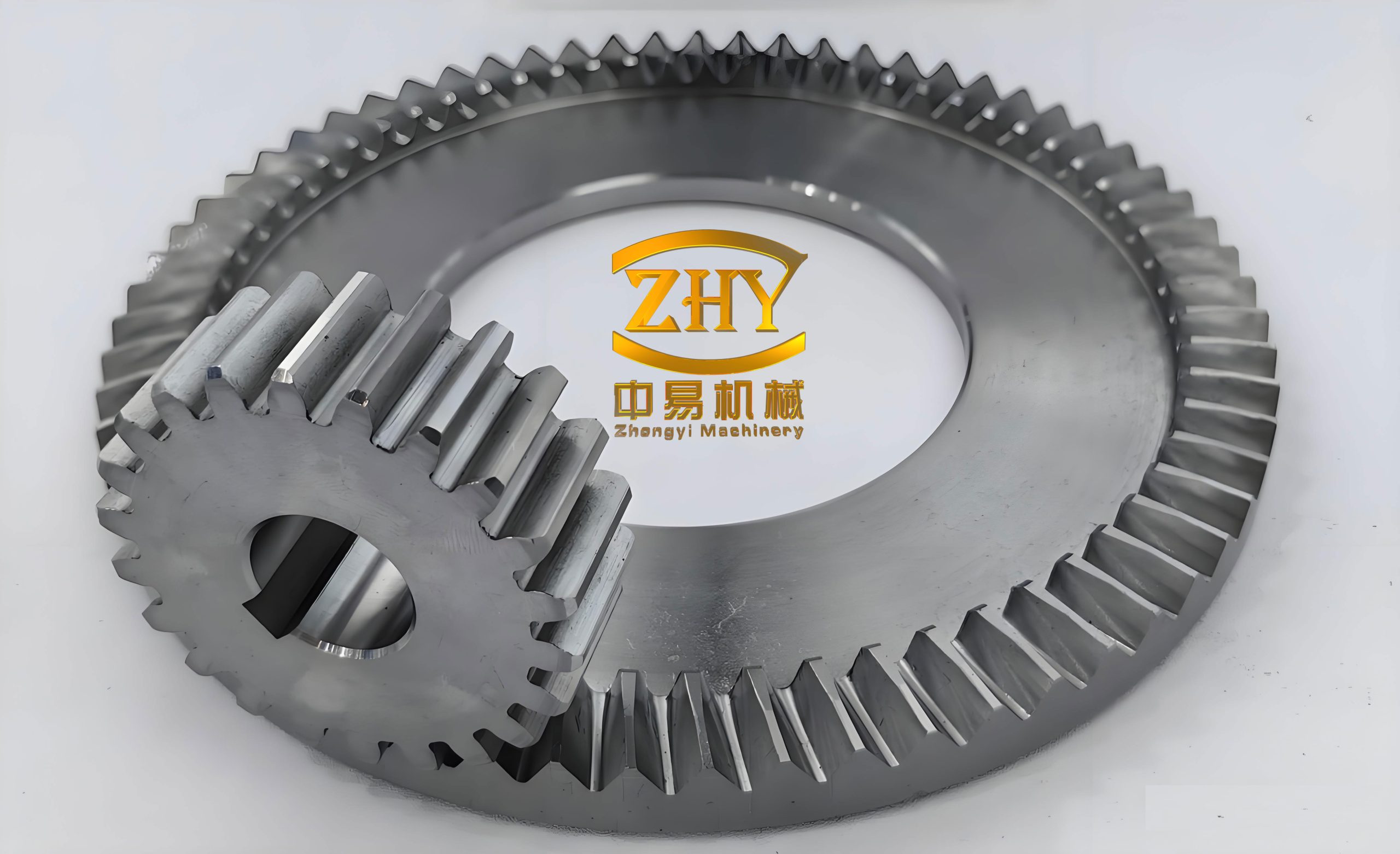
The face gear concept is important because a face gear can transmit motion between intersecting axes while offering compact packaging, high load capacity, and favorable load sharing. When the face gear is also asymmetric, the two sides of each tooth can be designed for different duties. A non-orthogonal asymmetric face gear drive therefore combines geometric flexibility with asymmetric tooth performance. I treat the cylindrical gear as gear 1 and the non-orthogonal asymmetric face gear as gear 2. The mesh process is represented along the line of action, and the relative displacement along that line becomes the primary nonlinear state variable. The backlash function introduces piecewise stiffness and damping terms, which are responsible for the loss of contact, reverse impact, and the transition between single-sided and double-sided contact. I include these effects because they are essential for a credible nonlinear dynamic analysis of any face gear system.
Modeling Assumptions and Symbolic Framework
I model the non-orthogonal asymmetric face gear transmission system as a lumped-parameter system. The cylindrical gear and the face gear each have three translational degrees of freedom along the x, y, and z axes. The rotational motion is condensed into the torsional mesh direction, so the relative displacement along the line of action captures the dominant vibration. I assume that the support bearings are linear in each coordinate direction, that the mesh stiffness is periodic with the mesh frequency, and that the transmission error is also periodic. The backlash is modeled as a symmetric clearance in the normalized coordinate, while the asymmetric tooth geometry enters through the pressure angle and the non-orthogonal geometry enters through the shaft angle. The face gear mesh is therefore not a simple orthogonal face gear mesh; it is a non-orthogonal asymmetric face gear mesh with direction-dependent force projection.
| Symbol | Meaning |
|---|---|
| Gear 1 | Cylindrical gear of the non-orthogonal asymmetric face gear pair |
| Gear 2 | Non-orthogonal asymmetric face gear |
| M1, M2 | Masses of gear 1 and gear 2 |
| I1, I2 | Rotational inertias of gear 1 and gear 2 |
| r1, r2 | Base radii of gear 1 and gear 2 |
| alpha | Normal pressure angle of the face gear tooth flank |
| beta | Helix angle |
| delta | Shaft angle of the non-orthogonal face gear pair |
| Fn | Normal mesh force |
| Fm | External excitation force |
| P | Relative displacement along the face gear mesh line |
| bn | Characteristic displacement for normalization |
| cn | Mesh damping coefficient |
| k(t) | Time-varying mesh stiffness of the face gear pair |
| en(t) | Transmission error of the face gear pair |
| Omega_h | Mesh frequency of the face gear pair |
| omega_n | Natural frequency used for nondimensionalization |
| lambda | Dimensionless relative displacement along the face gear mesh line |
Load, Torque, and Equivalent Mass of the Face Gear Pair
I define the driving torque on the cylindrical gear and the resisting torque on the face gear. The torque relation includes both a mean component and a fluctuating component. The equivalent mass of the face gear transmission system is obtained by combining the rotational inertias and the base radii. These quantities determine how the rotational motion of the face gear pair is projected onto the translational mesh line. I write the driving torque of gear 1 as
$$T_1=F_{1a}r_1+F_{1b}\frac{I_1r_2^2+I_2r_1^2}{I_2r_1}$$
where F1a is the mean part of the force on gear 1, F1b is the fluctuating part, I1 and I2 are the rotational inertias, and r1 and r2 are the base radii. The resisting torque of gear 2 is
$$T_2=F_2r_2$$
where F2 is the circumferential force on the face gear. The equivalent mass of the non-orthogonal asymmetric face gear transmission system is
$$M_e=\frac{I_1I_2}{I_1r_2^2+I_2r_1^2}$$
I also use the torque-force relations
$$T_1=(F_{1a}+F_{1b})r_1+I_1\ddot{\phi}_1$$
$$T_2=F_2r_2-I_2\ddot{\phi}_2$$
where phi1 and phi2 are the angular rotations of gear 1 and gear 2. These relations allow me to condense the rotational dynamics into the translational mesh coordinate. The face gear mesh is thus represented as a nonlinear oscillator with parametric excitation from the time-varying mesh stiffness and external excitation from the transmission error and force fluctuation. Because the system is a non-orthogonal asymmetric face gear drive, the force projection depends on both the pressure angle and the shaft angle. This coupling is the main reason why the nonlinear response of the face gear system is so sensitive to excitation frequency.
| Parameter | Gear 1 | Gear 2 |
|---|---|---|
| Number of teeth | 23 | 85 |
| Mass (kg) | 3 | 12 |
| Module (mm) | 4 | 4 |
| Helix angle (deg) | 20 | 20 |
| Rotational inertia (kg m^2) | 0.005 | 2.270 |
| Support stiffness (N/m) | 1e8 | 6e8 |
| Support damping (N s/m) | 6e3 | 1e4 |
Translational Equations of the Non-Orthogonal Asymmetric Face Gear System
I now write the dimensional vibration equations for the cylindrical gear and the face gear. The cylindrical gear has three translational coordinates X1, Y1, and Z1. The face gear has three translational coordinates X2, Y2, and Z2. The mesh force Fn is projected onto each coordinate through the pressure angle and helix angle. For gear 1, I obtain
$$M_1\ddot{X}_1+c_{x1}\dot{X}_1+k_{x1}X_1=-F_n\cos\alpha\sin\beta$$
$$M_1\ddot{Y}_1+c_{y1}\dot{Y}_1+k_{y1}Y_1=-F_n\cos\alpha\cos\beta$$
$$M_1\ddot{Z}_1+c_{z1}\dot{Z}_1+k_{z1}Z_1=-F_n\sin\alpha$$
For gear 2, which is the non-orthogonal asymmetric face gear, the projections include the shaft angle delta. I write
$$M_2\ddot{X}_2+c_{x2}\dot{X}_2+k_{x2}X_2=F_n\cos\alpha\sin\beta\sin(90^\circ-\delta)$$
$$M_2\ddot{Y}_2+c_{y2}\dot{Y}_2+k_{y2}Y_2=F_n\cos\alpha\cos\beta$$
$$M_2\ddot{Z}_2+c_{z2}\dot{Z}_2+k_{z2}Z_2=F_n\sin\alpha\cos(90^\circ-\delta)$$
Here, cxi and cyi and czi are the support damping coefficients, and kxi and kyi and kzi are the support stiffness coefficients. The subscript i equals 1 for the cylindrical gear and 2 for the non-orthogonal asymmetric face gear. The term sin(90 degrees minus delta) and cos(90 degrees minus delta) show how the non-orthogonal geometry changes the projection of the mesh force onto the face gear coordinates. When delta is not 90 degrees, the face gear force distribution is no longer the same as in an orthogonal face gear drive. This is a key feature of the non-orthogonal face gear system.
The relative displacement along the face gear mesh line is denoted P. I derive the mesh line equation by combining the translational accelerations of both gears. The result is
$$M_e\ddot{P}=M_e\ddot{Y}_1\cos\alpha\cos\beta-M_e\ddot{Y}_2\cos\alpha\cos\beta+M_e\ddot{X}_1\cos\alpha\sin\beta-M_e\ddot{X}_2\cos\alpha\sin\beta\sin(90^\circ-\delta)+M_e\ddot{Z}_1\sin\alpha-M_e\ddot{Z}_2\sin\alpha\cos(90^\circ-\delta)-k(t)f(P)\cos\alpha+c_n\dot{P}\cos\alpha+F_m\cos\alpha+M_e\ddot{e}_n(t)$$
In this equation, k(t) is the time-varying mesh stiffness, f(P) is the backlash function, cn is the mesh damping, Fm is the external excitation force, and en(t) is the transmission error. The term k(t) f(P) cos alpha represents the elastic mesh force, while cn Pdot cos alpha represents the dissipative mesh force. The transmission error term M e eddotn(t) acts as an internal excitation. This equation is the core of the nonlinear dynamic model of the non-orthogonal asymmetric face gear transmission system. It contains both geometric nonlinearity from the backlash and parametric excitation from the time-varying mesh stiffness.
Backlash Function and Mesh Force of the Face Gear Pair
I use a piecewise backlash function to describe the loss of contact and the reverse impact in the face gear mesh. In normalized form, the backlash function is
$$l(\lambda)=\begin{cases}\lambda-1,&\lambda>1\\0,&-1\le\lambda\le1\\\lambda+1,&\lambda<-1\end{cases}$$
When lambda is greater than one, the teeth are in forward contact. When lambda is less than minus one, the teeth are in reverse contact. When lambda lies between minus one and one, the teeth are in the backlash region and the mesh force from elastic deformation is zero. This piecewise behavior is one of the main sources of nonlinearity in the non-orthogonal asymmetric face gear system. The mesh force is computed as
$$F_n=k(t)l(\lambda)+c_n\dot{\lambda}$$
if the viscous mesh damping is included in the relative coordinate. I also represent the time-varying mesh stiffness by a Fourier series,
$$k(\tau)=k_0+\sum_{r=1}^{N}k_r\cos(r\Omega_e\tau+\phi_r)$$
where Omega_e is the dimensionless mesh frequency. The transmission error is represented in a similar way,
$$e_n(\tau)=e_0+\sum_{r=1}^{N}e_r\sin(r\Omega_e\tau+\psi_r)$$
These periodic terms introduce parametric and external excitation into the face gear system. Because the face gear pair is non-orthogonal and asymmetric, the pressure angle and the shaft angle alter the effective projection of these excitations. I therefore treat alpha and delta as important control parameters in the nonlinear analysis.
Nondimensionalization of the Face Gear Dynamic Equations
The dimensional equations contain quantities with very different orders of magnitude. To improve numerical conditioning and to make the bifurcation analysis easier, I nondimensionalize the equations. I introduce the following normalized coordinates and time:
$$x_i=\frac{X_i}{b_n},\quad y_i=\frac{Y_i}{b_n},\quad z_i=\frac{Z_i}{b_n},\quad \lambda=\frac{P}{b_n},\quad \tau=\omega_n t$$
I also define the dimensionless damping and stiffness coefficients as
$$\zeta_n=\frac{c_n}{2M_e\Omega_h/\omega_n}$$
$$\kappa_{ij}=\frac{k_{ij}/M_i}{(\Omega_h/\omega_n)^2}$$
$$\kappa_{ni}=\frac{k(t)}{M_1(\Omega_h/\omega_n)^2}=\frac{M_e}{M_i}\kappa(\tau)$$
$$f_m=\frac{\cos\alpha F_m}{b_n M_e(\Omega_h/\omega_n)^2}$$
$$\zeta_{ni}=\frac{c_n}{2M_i\Omega_h/\omega_n}$$
$$\zeta_{ji}=\frac{c_{ij}}{2M_i\Omega_h/\omega_n}$$
Here, i equals 1 or 2, and j denotes x, y, or z. The dimensionless mesh frequency is Omega_e equals Omega_h divided by omega_n. After these substitutions, the cylindrical gear equations become
$$\ddot{x}_1+2\zeta_{x1}\dot{x}_1+2\cos\alpha\sin\beta\zeta_{n1}\dot{\lambda}+\kappa_{x1}x_1+\cos\alpha\sin\beta\kappa_{n1}l(\lambda)=0$$
$$\ddot{y}_1+2\zeta_{y1}\dot{y}_1+2\cos\alpha\cos\beta\zeta_{n1}\dot{\lambda}+\kappa_{y1}y_1+\cos\alpha\cos\beta\kappa_{n1}l(\lambda)=0$$
$$\ddot{z}_1+2\zeta_{z1}\dot{z}_1+2\sin\alpha\zeta_{n1}\dot{\lambda}+\kappa_{z1}z_1+\sin\alpha\kappa_{n1}l(\lambda)=0$$
For the non-orthogonal asymmetric face gear, the dimensionless equations become
$$\ddot{x}_2+2\zeta_{x2}\dot{x}_2-2\cos\alpha\sin\beta\sin(90^\circ-\delta)\zeta_{n2}\dot{\lambda}+\kappa_{x2}x_2-\cos\alpha\sin\beta\sin(90^\circ-\delta)\kappa_{n2}l(\lambda)=0$$
$$\ddot{y}_2+2\zeta_{y2}\dot{y}_2-2\cos\alpha\cos\beta\zeta_{n2}\dot{\lambda}+\kappa_{y2}y_2-\cos\alpha\cos\beta\kappa_{n2}l(\lambda)=0$$
$$\ddot{z}_2+2\zeta_{z2}\dot{z}_2+\kappa_{z2}z_2-2\sin\alpha\cos(90^\circ-\delta)\zeta_{n2}\dot{\lambda}-\sin\alpha\cos(90^\circ-\delta)\kappa_{n2}l(\lambda)=0$$
The dimensionless mesh line equation is
$$\ddot{\lambda}+2\cos\alpha\zeta_n\dot{\lambda}+\cos\alpha\kappa(\tau)l(\lambda)-\cos\alpha\sin\beta\ddot{x}_1+\cos\alpha\sin\beta\sin(90^\circ-\delta)\ddot{x}_2-\cos\alpha\cos\beta\ddot{y}_1+\cos\alpha\cos\beta\ddot{y}_2-\sin\alpha\ddot{z}_1+\sin\alpha\cos(90^\circ-\delta)\ddot{z}_2-f_m=0$$
This set of coupled differential equations governs the nonlinear dynamics of the non-orthogonal asymmetric face gear transmission system. The equations are integrated in time with a fourth-order Runge-Kutta method. I use a sufficiently small time step to capture the impact-like behavior caused by backlash and to resolve the high-frequency components that appear in the chaotic state. The initial transient is discarded before I construct phase portraits, Poincare sections, spectra, and bifurcation diagrams. This procedure allows me to identify the nonlinear state of the face gear system at each excitation frequency.
Numerical Integration and Nonlinear Response Measures
I solve the dimensionless equations with the classical fourth-order Runge-Kutta scheme,
$$y_{n+1}=y_n+\frac{h}{6}(k_1+2k_2+2k_3+k_4)$$
$$k_1=f(t_n,y_n)$$
$$k_2=f\left(t_n+\frac{h}{2},y_n+\frac{h}{2}k_1\right)$$
$$k_3=f\left(t_n+\frac{h}{2},y_n+\frac{h}{2}k_2\right)$$
$$k_4=f(t_n+h,y_n+h k_3)$$
where h is the time step and y is the state vector containing all displacements and velocities of the non-orthogonal asymmetric face gear system. The state vector includes x1, y1, z1, x2, y2, z2, lambda, and their first derivatives. The numerical integration produces the time-domain response, from which I extract the phase portrait in the lambda-lambdadot plane. I also construct the Poincare map
$$\Sigma=\{(x,v,t):t=t_0+nT\}$$
$$P:\Sigma\to\Sigma,\quad P(x_n,v_n)=(x_{n+1},v_{n+1})$$
where T is the period of the external excitation. The Poincare section allows me to distinguish a single-period orbit, a period-doubled orbit, and a chaotic attractor. For a single-period state, the Poincare map contains one point. For a double-period state, it contains two point sets. For a chaotic state, it contains a disordered set of points. I further compute the spatial spectrum
$$S(\omega)=\left|\int_{-\infty}^{\infty}x(\tau)e^{-i\omega\tau}\,d\tau\right|^2$$
to identify the dominant frequency components. In the single-period state, the spectrum peaks near the excitation frequency. In the double-period state, a prominent subharmonic peak appears near one half of the excitation frequency. In the chaotic state, many small-amplitude harmonics appear around the subharmonic and its multiples. The bifurcation diagram is obtained by plotting the local maxima of lambda versus the excitation frequency after the transient has decayed. This diagram reveals the transitions from periodic motion to period doubling to chaos in the non-orthogonal asymmetric face gear system.
| State | Excitation-frequency range | Phase portrait | Poincare section | Spectrum |
|---|---|---|---|---|
| Single period | Approximately 1.80 to 1.84 | One closed loop | One point | Main peak near 1.0 |
| Double period | Above 1.84 up to about 2.02 | Two closed loops | Two point sets | Peaks near 0.5 and 1.0 |
| Chaos | Above about 2.02 | Interlaced loops | Disordered points | Many harmonics near 0.5 |
Influence of Pressure Angle on the Face Gear Nonlinear Response
I first fix the shaft angle at 60 degrees and vary the pressure angle of the asymmetric face gear teeth. The pressure angle takes the values 15, 20, 25, and 30 degrees. This range is representative for the non-orthogonal asymmetric face gear drive considered here. For each pressure angle, I sweep the dimensionless excitation frequency and record the time-domain response, phase portrait, Poincare section, spatial spectrum, and bifurcation diagram. I observe that the face gear system follows the same qualitative route in every case: single-period motion at low excitation frequency, period doubling as the frequency increases, and chaos at higher frequency. However, the amplitude of the chaotic vibration depends strongly on the pressure angle. As the pressure angle decreases, the chaotic vibration displacement of the non-orthogonal asymmetric face gear system becomes smaller. This result indicates that a lower pressure angle can improve the stability of the face gear transmission system within the studied range.
When the excitation frequency is 1.82, the phase portrait is a single closed loop and the Poincare section is a single point. The face gear system is in a stable single-period state. When the excitation frequency is 1.85, the phase portrait splits into two closed loops and the Poincare section contains two point sets. The face gear system is in a period-doubled state. When the excitation frequency reaches 2.04, the phase portrait becomes a set of interlaced loops and the Poincare section becomes a scattered set of points. The face gear system is then in a chaotic state. The time-domain response in the chaotic state is irregular and lacks a clear period. The spatial spectrum in the single-period state is concentrated near the fundamental frequency. In the period-doubled state, a strong subharmonic peak appears. In the chaotic state, the spectrum becomes broad and contains many low-amplitude components. These features are characteristic of nonlinear face gear dynamics.
| Pressure angle (deg) | Chaotic vibration displacement | Stability trend | Observed route |
|---|---|---|---|
| 15 | Smallest | Most stable among the tested pressure angles | Single period, double period, chaos |
| 20 | Small | Improved stability | Single period, double period, chaos |
| 25 | Moderate | Moderate stability | Single period, double period, chaos |
| 30 | Largest | Least stable among the tested pressure angles | Single period, double period, chaos |
The bifurcation diagrams confirm the time-domain and phase-space observations. For each pressure angle, the bifurcation diagram is a single line at low excitation frequency, which means that the face gear system is in a single-period state. When the excitation frequency exceeds approximately 1.84, the first bifurcation appears and the face gear system enters the period-doubled state. When the excitation frequency exceeds approximately 2.02, the bifurcation diagram becomes a broad band of points, which indicates chaos. Although the transition frequencies are similar for the different pressure angles, the width of the chaotic band and the maximum displacement are different. A lower pressure angle produces a narrower chaotic band and a smaller vibration displacement. This behavior is important for the design of a non-orthogonal asymmetric face gear transmission because it suggests that the asymmetric pressure angle can be selected to reduce chaotic vibration without changing the overall transition route.
Influence of Shaft Angle on the Face Gear Nonlinear Response
I next fix the pressure angle at 20 degrees and vary the shaft angle of the non-orthogonal face gear pair. The shaft angle takes the values 0, 30, 60, and 90 degrees. This set covers a wide range of non-orthogonal face gear configurations. For each shaft angle, I perform the same frequency sweep and construct the same nonlinear response measures. I again observe the sequence of single-period motion, period doubling, and chaos. The phase portrait at an excitation frequency of 1.82 is a single closed loop, and the Poincare section is a single point. At an excitation frequency of 1.85, the phase portrait has two closed loops and the Poincare section has two point sets. At an excitation frequency of 2.01, the phase portrait becomes a set of interlaced loops and the Poincare section becomes a disordered point set. These results show that the non-orthogonal asymmetric face gear system has the same qualitative nonlinear behavior for different shaft angles, but the quantitative vibration amplitude changes significantly.
The time-domain responses show stable periodic waveforms in the period-doubled state and irregular waveforms in the chaotic state. When the excitation frequency is 1.85, the face gear system is in the period-doubled state, and the time-domain waveform is regular even though the shaft angle changes. When the excitation frequency is 2.10, the time-domain waveform is disordered, which is consistent with chaos. The spatial spectrum in the single-period state has a dominant peak near the excitation frequency. In the period-doubled state, the spectrum has peaks near one half and one times the excitation frequency. In the chaotic state, the spectrum contains many small-amplitude harmonic components, especially near the subharmonic frequency. As the shaft angle increases, the chaotic vibration displacement decreases. This trend indicates that a larger shaft angle can improve the stability of the non-orthogonal asymmetric face gear transmission system. In other words, when the face gear system can operate normally, increasing the shaft angle is a useful way to reduce chaotic vibration in the non-orthogonal face gear drive.
| Shaft angle (deg) | Chaotic vibration displacement | Stability trend | Observed route |
|---|---|---|---|
| 0 | Largest | Lowest stability among the tested shaft angles | Single period, double period, chaos |
| 30 | Lower | Improved stability | Single period, double period, chaos |
| 60 | Moderate | Moderate stability | Single period, double period, chaos |
| 90 | Smallest | Highest stability among the tested shaft angles | Single period, double period, chaos |
The bifurcation diagrams for the different shaft angles show the same qualitative pattern. The face gear system is single-period when the excitation frequency is between 1.80 and 1.84. Period doubling begins after approximately 1.84. Chaos begins after approximately 2.02. However, the chaotic band is narrower and the vibration displacement is smaller when the shaft angle is larger. This means that the non-orthogonal geometry can be used as a design parameter to tune the chaotic response of the face gear system. A larger shaft angle increases the projection of the mesh force onto certain coordinates and changes the effective coupling between the two gears. This coupling change modifies the energy distribution among the vibration modes and reduces the amplitude of the chaotic attractor. The result is a more stable face gear transmission system.
| Case | Pressure angle (deg) | Shaft angle (deg) | Primary purpose |
|---|---|---|---|
| A | 15 | 60 | Low pressure-angle effect in a non-orthogonal face gear |
| B | 20 | 60 | Reference asymmetric face gear case |
| C | 25 | 60 | Medium pressure-angle effect |
| D | 30 | 60 | High pressure-angle effect |
| E | 20 | 0 | Low shaft-angle face gear configuration |
| F | 20 | 30 | Moderate non-orthogonal face gear configuration |
| G | 20 | 60 | Reference non-orthogonal face gear configuration |
| H | 20 | 90 | Orthogonal-like face gear configuration |
Comparative Synthesis of Frequency, Pressure Angle, and Shaft Angle
I synthesize the results by comparing the nonlinear response of the non-orthogonal asymmetric face gear system under different pressure angles and shaft angles. The excitation frequency is the main control parameter that drives the transition from order to chaos. At low excitation frequency, the face gear system is single-period. As the excitation frequency increases, the first period-doubling bifurcation occurs. With a further increase, the face gear system enters chaos through a cascade of period-doubling bifurcations. This route is robust across the pressure angles and shaft angles that I investigate. The nonlinearity caused by backlash is always present, and the time-varying mesh stiffness introduces parametric excitation that interacts with the external excitation. The result is a rich set of nonlinear phenomena in the face gear transmission system.
The pressure angle and shaft angle do not change the qualitative route, but they do change the quantitative severity of the chaotic response. A smaller pressure angle reduces the chaotic vibration displacement. A larger shaft angle also reduces the chaotic vibration displacement. Therefore, I can state that the stability of the non-orthogonal asymmetric face gear transmission system can be improved by choosing a smaller pressure angle or a larger shaft angle, provided that the gear strength, contact stress, and manufacturing constraints remain acceptable. This conclusion is important for the design of face gear drives used in high-speed and heavy-load applications. In such applications, even a modest reduction in chaotic vibration can reduce noise, wear, and fatigue loading.
| Control parameter | Change | Effect on chaotic displacement | Effect on stability |
|---|---|---|---|
| Excitation frequency | Increase from 1.80 to above 2.02 | Increases and becomes chaotic | Decreases |
| Pressure angle | Decrease from 30 to 15 degrees | Decreases | Increases |
| Shaft angle | Increase from 0 to 90 degrees | Decreases | Increases |
Time-Domain and Spectral Interpretation for the Face Gear System
The time-domain response of the non-orthogonal asymmetric face gear system provides a direct view of the nonlinear behavior. In the single-period state, the displacement lambda repeats itself with the period of the external excitation. The waveform is smooth and regular. In the double-period state, the waveform repeats every two excitation periods, and the corresponding subharmonic appears in the spectrum. In the chaotic state, the waveform never repeats, and the spectrum becomes broad. These features are consistent with the phase portraits and Poincare sections. I use the time-domain response to verify the nonlinear state identified by the bifurcation diagram. The agreement among these different measures gives confidence in the numerical results.
The spatial spectrum is especially useful because it shows how the vibration energy is distributed among frequencies. In the single-period state, the energy is concentrated at the excitation frequency and its harmonics. In the double-period state, the energy splits into the fundamental and the subharmonic. In the chaotic state, the energy is spread over many frequencies, and the subharmonic region contains a large number of small peaks. For the non-orthogonal asymmetric face gear system, the pressure angle and shaft angle change the amplitude of these peaks. A smaller pressure angle reduces the peak amplitudes in the chaotic region. A larger shaft angle also reduces the peak amplitudes. This spectral behavior supports the conclusion that the chaotic vibration of the face gear system can be mitigated by appropriate geometric selection.
| Response measure | Single-period state | Double-period state | Chaotic state |
|---|---|---|---|
| Time domain | Regular periodic waveform | Two-period waveform | Irregular aperiodic waveform |
| Phase portrait | One closed loop | Two closed loops | Interlaced loops |
| Poincare section | One point | Two point sets | Disordered points |
| Spatial spectrum | Peak at fundamental | Peak at subharmonic and fundamental | Many harmonics near subharmonic |
| Bifurcation diagram | Single line | Two branches | Broad band |
Stability Implication for Non-Orthogonal Asymmetric Face Gear Design
From an engineering perspective, the nonlinear dynamic analysis of the non-orthogonal asymmetric face gear system provides several design insights. First, the excitation frequency must be chosen carefully. If the face gear drive operates near the period-doubling or chaotic regions, the vibration amplitude may increase sharply. Second, the pressure angle of the asymmetric face gear tooth should be selected not only for strength and contact stress but also for dynamic stability. A lower pressure angle can reduce chaotic vibration, but it may also change the contact ratio and the load capacity. Third, the shaft angle of the non-orthogonal face gear pair should be considered as a dynamic tuning parameter. A larger shaft angle can reduce chaotic vibration, but it may also affect the assembly layout and the bearing loads. I therefore recommend a multi-objective design approach in which the pressure angle and shaft angle are optimized together with the mesh frequency and backlash.
The face gear transmission system is inherently nonlinear because of backlash, time-varying mesh stiffness, and transmission error. The non-orthogonal geometry adds additional coupling between the coordinate directions. The asymmetric tooth geometry adds different behavior on the drive and coast sides. These features make the non-orthogonal asymmetric face gear drive more complex than a simple orthogonal face gear drive. However, they also provide more design freedom. By selecting the pressure angle and shaft angle appropriately, I can shift the chaotic region, reduce the vibration displacement, and improve the operational stability of the face gear system. This is the main practical message of my analysis.
| Design variable | Recommended direction for stability | Possible trade-off |
|---|---|---|
| Pressure angle | Decrease within the feasible range | Contact stress, strength, and contact ratio may change |
| Shaft angle | Increase within the feasible range | Assembly layout and bearing loads may change |
| Excitation frequency | Avoid the period-doubling and chaotic bands | Operating speed may be constrained |
| Backlash | Control within a suitable tolerance | Manufacturing cost and impact sensitivity |
| Mesh stiffness | Reduce excessive fluctuation | Tooth modification and manufacturing complexity |
Numerical Observations Across the Bifurcation Route
I record the bifurcation route for the non-orthogonal asymmetric face gear system as follows. For excitation frequencies between 1.80 and 1.84, the system is single-period. The phase portrait is a closed curve, the Poincare section is a single point, and the spectrum has a dominant peak at the fundamental frequency. For excitation frequencies above 1.84 and up to approximately 2.02, the system is double-period. The phase portrait contains two closed curves, the Poincare section contains two point sets, and the spectrum has a strong subharmonic peak. For excitation frequencies above approximately 2.02, the system is chaotic. The phase portrait contains many interlaced curves, the Poincare section is a scattered set, and the spectrum contains a broad range of frequency components. These numerical observations are consistent across the pressure angles and shaft angles that I examine, although the amplitude of the chaotic motion changes with the geometric parameters.
I also note that the transition from single-period to double-period is not instantaneous in the bifurcation diagram. There is a narrow transition region in which the period-doubling cascade begins. In this region, the response may contain both periodic and weakly chaotic features. The exact width of this region depends on the damping, the mesh stiffness fluctuation, and the backlash. For the non-orthogonal asymmetric face gear system, the damping and stiffness coefficients are fixed in my parametric study, so the main changes come from the pressure angle and shaft angle. These geometric parameters change the force projection and therefore the effective nonlinearity of the face gear mesh. The result is a shift in the amplitude of the chaotic attractor rather than a complete change in the bifurcation route.
| Excitation frequency | State of the face gear system | Dominant dynamic feature |
|---|---|---|
| 1.82 | Single period | One closed phase loop and one Poincare point |
| 1.85 | Double period | Two closed phase loops and two Poincare sets |
| 2.01 | Chaos | Interlaced phase loops and disordered Poincare points |
| 2.04 | Chaos | Strongly irregular time response and broad spectrum |
| 2.10 | Chaos | Fully developed chaotic vibration |
Role of Backlash and Mesh Stiffness in the Face Gear Nonlinearity
The backlash function is the source of the piecewise nonlinearity in the face gear system. When the relative displacement is inside the backlash region, the mesh stiffness does not contribute to the restoring force. When the relative displacement crosses the backlash boundary, the mesh stiffness suddenly becomes active. This sudden change produces impact-like behavior and can excite high-frequency components. The time-varying mesh stiffness further modulates the restoring force. Because the mesh stiffness changes periodically with the mesh frequency, the face gear system is parametrically excited. The interaction between the backlash nonlinearity and the parametric excitation is responsible for the period-doubling and chaotic behaviors. In the non-orthogonal asymmetric face gear system, the pressure angle and shaft angle change the projection of the mesh force and therefore change the effective strength of this interaction. A smaller pressure angle reduces the projection of the mesh force in some directions, which can reduce the chaotic vibration. A larger shaft angle changes the projection in a way that also reduces the chaotic vibration. These effects are consistent with the numerical results.
I can express the effective mesh force on the face gear line of action as
$$F_{\mathrm{mesh}}=k(t)l(\lambda)+c_n\dot{\lambda}$$
The nonlinear restoring force is therefore
$$F_{\mathrm{restore}}=k(t)l(\lambda)$$
and the nonlinear damping force is
$$F_{\mathrm{damp}}=c_n\dot{\lambda}$$
The total excitation along the face gear mesh line is
$$F_{\mathrm{exc}}=F_m+M_e\ddot{e}_n(t)$$
These forces are projected onto the gear coordinates through the pressure angle, helix angle, and shaft angle. The projection factors are
$$p_x=\cos\alpha\sin\beta$$
$$p_y=\cos\alpha\cos\beta$$
$$p_z=\sin\alpha$$
For the non-orthogonal face gear, the projection factors include the shaft angle through sin(90 degrees minus delta) and cos(90 degrees minus delta). This geometric dependence is the reason why the shaft angle can be used to tune the nonlinear response of the face gear system. The pressure angle similarly changes the relative weight of the x, y, and z projections. By changing these projection factors, I change the energy transfer among the translational modes and the mesh line. This coupling is a key feature of the non-orthogonal asymmetric face gear drive.
| Projection factor | Expression | Influenced by |
|---|---|---|
| p_x | cos alpha sin beta | Pressure angle and helix angle |
| p_y | cos alpha cos beta | Pressure angle and helix angle |
| p_z | sin alpha | Pressure angle |
| Face gear x projection | p_x sin(90 degrees minus delta) | Pressure angle, helix angle, shaft angle |
| Face gear z projection | p_z cos(90 degrees minus delta) | Pressure angle and shaft angle |
Frequency-Domain Behavior of the Non-Orthogonal Asymmetric Face Gear
The frequency-domain behavior of the non-orthogonal asymmetric face gear system confirms the time-domain and phase-space results. In the single-period state, the spectrum is narrow and centered on the excitation frequency. In the double-period state, the spectrum contains a subharmonic component at half the excitation frequency. In the chaotic state, the spectrum becomes broad and contains many small peaks. I observe that the amplitude of these peaks depends on the pressure angle and shaft angle. When the pressure angle is reduced, the peak amplitudes in the chaotic region decrease. When the shaft angle is increased, the peak amplitudes also decrease. This frequency-domain trend is consistent with the reduction in chaotic vibration displacement observed in the time domain. Therefore, the spatial spectrum is a useful tool for assessing the stability of the non-orthogonal asymmetric face gear transmission system.
The bifurcation diagram is the most compact representation of the nonlinear dynamics. In the single-period region, the diagram is a single curve. In the period-doubled region, the curve splits into two branches. In the chaotic region, the diagram becomes a dense band of points. For the non-orthogonal asymmetric face gear system, the bifurcation diagram shows that the transition from order to chaos occurs at approximately the same excitation frequency for different pressure angles and shaft angles. However, the width of the chaotic band and the maximum vibration amplitude are different. A smaller pressure angle and a larger shaft angle both reduce the width of the chaotic band. This means that the face gear system can be made more robust by selecting the asymmetric pressure angle and the non-orthogonal shaft angle carefully.
| Frequency-domain feature | Single period | Double period | Chaos |
|---|---|---|---|
| Main peak | At excitation frequency | At excitation frequency and half frequency | Broad distribution |
| Subharmonic | Absent | Strong | Strong with many sidebands |
| Harmonics | Weak | Moderate | Many |
| Effect of lower pressure angle | Small change | Smaller subharmonic amplitude | Lower chaotic peaks |
| Effect of larger shaft angle | Small change | Smaller subharmonic amplitude | Lower chaotic peaks |
Engineering Guidelines Derived from the Face Gear Analysis
I derive several engineering guidelines from the nonlinear dynamic analysis of the non-orthogonal asymmetric face gear system. The first guideline is to avoid operating the face gear drive near the chaotic onset frequency. The onset is approximately 2.02 in the dimensionless frequency scale used here, but the exact value depends on the absolute mesh frequency, damping, and stiffness. The second guideline is to prefer a lower pressure angle when the strength and contact requirements allow it. A lower pressure angle reduces the chaotic vibration displacement and improves the stability of the face gear transmission. The third guideline is to prefer a larger shaft angle when the layout and bearing constraints allow it. A larger shaft angle also reduces the chaotic vibration displacement. The fourth guideline is to control backlash carefully. Too much backlash enlarges the nonlinear dead zone and increases impact severity. Too little backlash increases the risk of interference and high contact stress. A proper backlash tolerance is therefore essential for a stable face gear drive.
I also note that the non-orthogonal asymmetric face gear system has a strong coupling between the translational modes and the mesh line. This coupling means that a change in one coordinate direction can influence the nonlinear response in another direction. The pressure angle and shaft angle modify this coupling. As a result, a design that is optimized for one operating condition may not be optimal for another. I therefore recommend that the nonlinear dynamic analysis be performed over the full operating range of the face gear drive. The bifurcation diagram, phase portrait, Poincare section, and spatial spectrum should all be used together to assess stability. A single measure is not sufficient to characterize the complex behavior of the non-orthogonal asymmetric face gear system.
| Guideline | Action | Expected benefit for the face gear system |
|---|---|---|
| Frequency selection | Avoid the chaotic onset region | Reduced vibration and noise |
| Pressure angle | Reduce within feasible limits | Lower chaotic displacement |
| Shaft angle | Increase within feasible limits | Improved dynamic stability |
| Backlash control | Maintain an optimal tolerance | Reduced impact and wear |
| Mesh stiffness | Reduce excessive fluctuation | Weaker parametric excitation |
| Design validation | Use multiple nonlinear measures | Reliable stability assessment |
Conclusion of the Nonlinear Face Gear Investigation
I have constructed a nonlinear dynamic model of a non-orthogonal asymmetric face gear transmission system with backlash. I solved the governing equations with a fourth-order Runge-Kutta method and analyzed the time-domain response, phase portraits, Poincare sections, spatial spectra, and bifurcation diagrams. The results show that the non-orthogonal asymmetric face gear system exhibits single-period, double-period, and chaotic states as the excitation frequency increases. The transition from single-period to double-period occurs at a lower excitation frequency than the transition from double-period to chaos. The chaotic state is characterized by irregular time-domain waveforms, interlaced phase trajectories, scattered Poincare points, and broad frequency spectra. These features are robust across the pressure angles and shaft angles that I studied.
The pressure angle and shaft angle strongly affect the amplitude of the chaotic vibration. When the pressure angle decreases within a certain range, the chaotic vibration displacement of the non-orthogonal asymmetric face gear system decreases. When the shaft angle increases within a certain range, the chaotic vibration displacement also decreases. These trends indicate that both parameters can be used to improve the stability of the face gear transmission system. A lower pressure angle and a larger shaft angle reduce the effective nonlinear coupling and the projection of the mesh force in the chaotic region. As a result, the face gear system becomes more stable. This conclusion is useful for the design of non-orthogonal asymmetric face gear drives in high-speed and heavy-load applications.
In summary, the nonlinear dynamics of the non-orthogonal asymmetric face gear system are rich and strongly dependent on the excitation frequency, pressure angle, and shaft angle. The face gear drive can move from order to chaos through period doubling. The chaotic vibration can be reduced by selecting a smaller pressure angle or a larger shaft angle. These findings provide a foundation for the dynamic design and stability optimization of non-orthogonal asymmetric face gear transmission systems.